Also Inside: Photonics Worldwide-This is My Lab Industy Engagement: Project Management - IEEE Photonics Society
←
→
Page content transcription
If your browser does not render page correctly, please read the page content below

February 2020
Vol. 34, No. 1
www.PhotonicsSociety.org

                Research Highlight: Ideal Telecom Lasers

  Also Inside:
  • Photonics Worldwide—This is My Lab
  • Industy Engagement: Project Management
Introducing IEEE Collabratec™
The premier networking and collaboration site for technology
professionals around the world.

IEEE Collabratec is a new, integrated online community where IEEE members,
                                                                                       Network.
researchers, authors, and technology professionals with similar fields of interest
can network and collaborate, as well as create and manage content.                   Collaborate.
Featuring a suite of powerful online networking and collaboration tools,                  Create.
IEEE Collabratec allows you to connect according to geographic location,
technical interests, or career pursuits.

You can also create and share a professional identity that showcases key
accomplishments and participate in groups focused around mutual interests,
actively learning from and contributing to knowledgeable communities.
All in one place!

Learn about IEEE Collabratec at
ieee-collabratec.ieee.org
February 2020 Volume 34, Number 1

FEATURE

Research Highlight . . . . . . . . . . . . . . . . . . . . . . . . . . . . . . . . . . . . . . . . . . . . . . . . . . . . . . . . . . . . . . . . . . . . . . . . . . .4
– Routes to Ideal Telecom Lasers?

 15                                                       Industry Engagement . . . . . . . . . . . . . . . . . . . . . . . . . . . . . . . . . . . . . . . . . . . 10
                                                          •   Life at a Photonics Startup: Lessons Learned
                                                          Get to Know Your IEEE Photonics Society Leadership . . . . . . . . . . . . . . . . 15
                                                          Photonics Worldwide—This is My Lab. . . . . . . . . . . . . . . . . . . . . . . . . . . . . . 17
                                                          News . . . . . . . . . . . . . . . . . . . . . . . . . . . . . . . . . . . . . . . . . . . . . . . . . . . . . . . . . 19
                                                          •   2019 IEEE Electron Devices Society Education Award Winner
                                                          •   Jelena Vuckovic named the winner of the IET A F Harvey Engineering Research
                                                              Prize Research Grant to Create Revolutionary Miniature On-Chip Laser
                                                          •   The IEEE Learning Network (ILN): Your Place to Find IEEE Continuing Education
                                                          •   In Memoriam: William K. Burns (1943–2019)
                                                          Careers and Awards . . . . . . . . . . . . . . . . . . . . . . . . . . . . . . . . . . . . . . . . . . . . 22
                                                          •   Roel Baets Named 2020 John Tyndall Award Recipient
                                                          •   Meet the Newly Elected Members of the Board of Governors 2020–2022
                                                          •   The 2020 IEEE Photonics Society Young Investigator Award Recipient Mikhail Kats
                                                          •   Petition for Candidates—Photonics Society Board of Governors
                                                          •   Call for Nominations-IEEE Photonics Society 2020 Distinguished Service Award
                                                          •   Call for Nominations-IEEE Photonics Society Awards
                                                          •   IEEE Photonics Society Fellows—Class of 2020
 27                                                       Membership . . . . . . . . . . . . . . . . . . . . . . . . . . . . . . . . . . . . . . . . . . . . . . . . . . . 28
                                                          •   Chapter Best Practice: The University of Warsaw’s Student Chapter
                                                              ‘MiniModes Photonics School’
                                                          •   IEEE West European Student and Young Professional Congress (WESYP) 2019
                                                              Spotlight
                                                          •   Chapter Spotlight: Formation of the Student Chapter at the University of Strathclyde
                                                          •   NSBP Conference 2019: “Promoting Professional Connections and
                                                              Persistence in Physics”
                                                          •   IEEE NMDC2019 Special Event on Women in Innovation and Sustainability
                                                          •   IEEE Senior Member Initiative: How to Apply or Nominate in 2020
                                                          •   IEEE Photonics Society Honors Recently Elevated Senior Members
                                                          Conferences. . . . . . . . . . . . . . . . . . . . . . . . . . . . . . . . . . . . . . . . . . . . . . . . . . . 41
                                                          •   IEEE Photonics Society Calendar
                                                          •   Industry Day at IPC 2019
                                                          •   Conference Spotlight: Best Practices Learned at the “National Diversity
                                                              in STEM Conference”
                                                          •   Mentorship & New Soft-Skills Trainings Featured at ACP 2019
                                                          •   IEEE WRAP 2019 Spotlight: Indian Institute of Technology Guwahati
                                                          •   Call for Papers-Optical Interconnects 2020
 43                                                       •   Call for Papers-Summer Topicals 2020
                                                          •   Call for Papers-CLEO Pacific Rim 2020
                                                          •   Call for Papers-RAPID 2020
                                                          •   Call for Papers-Group IV Photonics 2020
                                                          •   Call for Papers-IEEE Photonics Conference 2020
                                                          •   Call for Papers-International Semiconductor Laser Conference 2020
                                                          •   Optical Fiber Communications Conference Exhibition Makes Top 100
                                                              in Trade Show Executive Magazine
                                                          •   IEEE Photonics Society Co-Sponsored Events
                                                          Publications . . . . . . . . . . . . . . . . . . . . . . . . . . . . . . . . . . . . . . . . . . . . . . . . . . . 54
                                                              – JLT CFP: Microwave Photonics
                                                              – JSTQE CFP: Photonics Antennas
                                                              – JSTQE CFP: Optical Signal Processing
                                                              – JSTQE CFP: Advanced Photonic Modulation
                                                              – JSTQE CFP: Biophotonics
                                                              – JSTQE CFP: Nanobiophotonics

            COLUMNS

                        Editor’s Column . . . . . . . . . . 2                              President’s Column . . . . . . . . . . . 3

February 2020                                                                                                IEEE PHOTONICS SOCIETY NEWSLETTER                                  1
Editor’s IEEE Photonics Society
Column
NICOLAS FONTAINE
President National Autonomous University of
Carmen Menoni Mexico
Welcome 2020! Each new year the Photonics Society Colorado State University USA Circuito Exterior s / n, Ciudad
Phone: 970-491-8659/555 Universitaria,
leadership changes and awards, honors and distinc- Email: c.menoni@ieee.org AP 70-360; Coyoacán,
Mexico City 04510, Mexico
tions are recognized. We welcome Carmen Menoni as Past President Email: jhcordero@iim.unam.mx
the new Photonics Society president and have four new Chennupati Jagadish
Associate Editor of Asia & Pacific
Australian National University
members of the board of governors, Akihiko Kasukawa, Nicholas H. L. Wong
Canberra, Australia GLOBALFOUNDRIES Singapore Pte. Ltd.
Milan Mashanovitch, Lief Oxenloewe, and Michelle Ph: +61-2-61250363 60 Woodlands Industrial Park D Street 2
Email: ChennupatiJagadish@anu Singapore 738406
Sander. In addition, the newsletter awards section rec- .edu.au Email: n.hl.wong@ieee.org
ognizes the new class of IEEE fellows. If you run into Secretary-Treasurer Associate Editor of Northern Europe
them, please take the time to congratulate them on Paul Juodawlkis Martin Lavery
MIT Lincoln Laboratory School of Engineering
their accomplishments. 244 Wood Street Rankine Building
University of Glasgow
The newsletter also has quite a bit of new content Lexington, MA 02421-6426
Oakfield Avenue
Tel: + 1 781 981 7895
contributed from our young professionals. We have Email: juodawlkis@ll.mit.edu G12 8LT
Martin.Lavery@glasgow.ac.uk
added two new student editors this month. Naznin Ak- Board of Governors
Associate Editor of Southern Europe
ter is running the Get to Know your Photonics Society C. Cincotti N. Nishiyama
Ivana Gasulla
N. Fontaine A. Peacock
Leadership column and Senta Jantzen is developing a ITEAM Research Institute
M. Hutchinson S. Ralph Universitat Politècnica de València
new column featuring young researchers working inside T. Kawanishi S. Savory Camino de Vera, 46022 Valencia
B. Lee M. Suzuki Spain
their labs. The membership section also contains several D. Marom J. Yao Email: ivgames@iteam.upv.es
articles describing events that the society has sponsored Vice Presidents Student Editor
that are written by the young professionals who have at- Conferences—Perry Shum Naznin Akter
Finance & Admin—Xiuling Li INSYST Integrated Nanosystems
tended them. Please check them out! Membership & Regional Research Laboratory
Electrical and Computer Engineering,
The research highlight, “Routes to Ideal Telecom Activities—René-Jean Essiambre
EC-3975
Publications—Aaron Hawkins
Lasers?”, is a tutorial describing the challenges and Technical Affairs—Lesile Ann Rusch Florida International University
10555 W Flagler Street.
techniques to fabricate efficient lasers in the telecom Newsletter Staff Miami, FL 33174
wavelengths. It is written by Christopher Broderick and Email: nakte001@fiu.edu
Editor-in-Chief
Nicolas Fontaine Student Editor
colleagues from the Tyndall National institute at the Senta L. Jantzen
Nokia Bell Laboratories
University College Cork which has a long history of la- 791 Holmdel Rd, Holmdel, NJ 07733 Optoelectronics Research Centre
732-888-7262 University of Southampton
ser expertise. I enjoyed learning why 1550 nm lasers are Southampton
Email: nicolas.fontaine@nokia.com
much less efficient than 900 nm lasers and that there are SO17 1BJ, UK
Associate Editor of Australia Email: s.jantzen@soton.ac.uk
still paths to improve the efficiency at 1550 nm. Joel Carpenter Staff Editor
The Industry Engagement column by Daniel Renner The University of Queensland Australia Lisa Sandt
Brisbane St Lucia, QLD 4072 IEEE Photonics Society
discusses the unique challenges facing photonics start- Email: j.carpenter@uq.edu.au 445 Hoes Lane
ups. This article draws insight from the construction of Associate Editor of Central, Latin and
Piscataway, NJ 08854
Tel: 1 732 465 6662
the Empire State Building which only took 13 months South American Fax: 1 732 981 1138
Juan A. Hernandez Cordero Email: ipsnewsletter@ieee.org
way back in 1931. My favorite lessons are #3, #7 and Institute of Materials Research
most importantly #12 (have fun)! Department of Rheology and
Mechanics of Materials
As another note, my tenure as Photonics Society
newsletter is ending at the end of this year! Time really
IEEE prohibits discrimination, harassment, and
does fly. My main goal is to get more people involved bullying. For more information, visit http://www.
in contributing content. Therefore, I encourage you to ieee.org/web/aboutus/whatis/policies/p9-26.html.
reach out to me if you would like to become involved
with the newsletter. Students, young professionals, and
IEEE Photonics Society News (USPS 014-023) is published bimonthly
experienced members can inquire about submitting by the Photonics Society of the Institute of Electrical and Electronics
an article! Engineers, Inc., Corporate Office: 3 Park Avenue, 17th Floor, New
York, NY 10017-2394. Printed in the USA. One dollar per member per
year is included in the Society fee for each member of the Photonics
Society. Periodicals postage paid at New York, NY and at additional
mailing offices. Postmaster: Send address changes to Photonics
Society Newsletter, IEEE, 445 Hoes Lane, Piscataway, NJ 08854.
Copyright © 2020 by IEEE: Permission to copy without fee all or part
of any material without a copyright notice is granted provided that
the copies are not made or distributed for direct commercial
advantage, and the title of the publication and its date appear on
each copy. To copy material with a copyright notice requires spe-
cific permission. Please direct all inquiries or requests to IEEE
Copyrights Office.
2 IEEE PHOTONICS SOCIETY NEWSLETTER February 2020
President’s
                   Column
                   CARMEN S. MENONI

I am honored and delighted to take on the responsibility of
serving as President of the IEEE Photonics Society over the
next two years and at the start of a new decade. These are ex-
citing times for Photonics in that research and technological
breakthroughs, from optical communications to devices and
from imaging and sensing to the printing of the most advanced
semiconductor chips with extreme ultraviolet light, are im-
pacting the world in many different ways. Together as a com-
munity we drive such innovation. In this vibrant environment,
the mission of the IEEE Photonics Society, to support the dis-
semination of knowledge and exchange of information, and to
contribute to the professional development of its members, is
increasingly relevant.
    I am starting the Presidency at a time in which the IEEE Pho-
tonics Society is in a very strong position. In 2019, the Society
passed its five-year IEEE review with glowing stars. Within the        munication tools to prioritize our marketing efforts and effec-
IEEE, our Society stands out for its innovative efforts and was com-   tively target audiences. There are also plans to collaborate with
mended for its operation and strategies. Publication highlights this   other internal, cross-discipline IEEE Societies and Councils to
year include partnering with IEEE Access to launch a special sec-      expand the IEEE brand, while bringing more visibility to the
tion dedicated to Photonics and co-sponsoring with other IEEE          Photonics Society.
societies a new, open access journal, the “IEEE Transactions in            Photonics is an interdisciplinary area that attracts engi-
Quantum Engineering,” that will launch in early-2020.                  neers, scientists and practitioners across many different special-
    The IEEE Photonics Society continues to have strong par-           ties. Towards the goal of making the IEEE Photonics Society a
ticipation at photonics conferences worldwide, including new           welcoming home for the broader worldwide community, I plan
conferences that will be co-sponsored in China, Singapore, and         to expand collaborations with international optics and photon-
Brazil. The Society is also engaged in new IEEE initiatives,           ics societies as well, and actively engage both the academic and
including IEEE Quantum Week, an IEEE Heterogeneous Inte-               industrial sectors to contribute to new initiatives that will im-
gration Roadmap and a newly established Photonics Standards            pact membership.
Committee with the IEEE Standards Association.                             The Society is in a healthy financial standing that will en-
    Membership is up with significant growth in Asia. In part,         able us to support new initiatives that will impact member-
this is the result of a significant investment of resources tar-       ship, publications and conferences. In concert with an excellent
geted towards students and young professionals. Globalization          team of Vice-Presidents, an engaged Board of Governors, and
and diversity initiatives have played a large part as well, as in-     the support of the Society staff, I am confident we will be able
clusive outreach is immersed in all aspects of our organization.       to materialize many of these initiatives.
To oversee these activities IEEE Photonics Society’s Diversity             I count, with your help, on accomplishing these efforts and
Oversight and Globalization Committees were created. A truly           goals. Members are the most invaluable assets to the IEEE
amazing level of activity and engagement has been displayed            Photonics Society.
by dedicated volunteer members and a superb staff.                         I wish you a productive and inspiring 2020!
    Moving forward, and building up on the efforts of previ-
ous presidents, I plan to focus on increasing the visibility of                                                     With Warm Regards,
the Society by implementing a ‘strategic marketing plan’ to                                                           Carmen S. Menoni
impact all of our products and services. Towards this goal, we                                                  Colorado State University
will make use of the parent IEEE’s resources and modern com-                                                           c.menoni@ieee.org

February 2020                                                                        IEEE PHOTONICS SOCIETY NEWSLETTER                3
Research Highlight
Routes to Ideal Telecom Lasers?
Christopher A. Broderick1,2, Sarita Das1,2, Emanuele Pelucchi 1,2,
Brian Corbett1,2, and Eoin P. O’Reilly1,2,*
1
  Tyndall National Institute, University College Cork, Lee Maltings,
Dyke Parade, Cork T12 R5CP, Ireland.
2
  Department of Physics, University College Cork, Cork T12 YN60, Ireland.
*
  eoin.oreilly@tyndall.ie

1. Introduction                                                        reflection, and also helps maximise the overlap between the
Ideal semiconductor lasers exploit very simple and clever phys-        carrier and optical modes for efficient lasing. Taking advan-
ics, with the best lasers offering very impressive characteristics     tage of these key features, the best GaAs-based lasers operat-
and performance. Figure 1 shows schematically three of the             ing at 980 nm have demonstrated wallplug efficiencies as high
key features of an edge-emitting laser diode. Firstly, the p-n         as 70%–i.e. 70% of input electrical power converted to laser
diode structure allows easy injection of electrons and holes to        output (optical) power–under laboratory conditions [1], with
give a local population inversion and stimulated emission at           currently available commercial devices displaying wallplug ef-
the band-gap energy of the active region. Secondly, the avail-         ficiencies approaching 60%.
ability of semiconductor materials and alloys possessing com-              Unfortunately, semiconductor laser efficiency is strongly
parable lattice constants but different band gaps presents the         wavelength dependent, with various intrinsic and extrinsic loss
ability to fabricate quantum-confined heterostructures–e.g.            mechanisms reducing device efficiency both at longer and at
quantum wells (QWs) and quantum dots (QDs)–which spa-                  shorter wavelengths. While 800–980 nm lasers are employed
tially trap electrons and holes in the active region, and suppress     in short-haul optical communications, this wavelength range
leakage current through the device. Thirdly, the varying band          offers limited potential for distances over 1 km or for use
gap profile has an associated varying refractive index profile,        in silicon photonics. High-bandwidth and long-haul com-
which acts to guide light within the active region via internal        munications and optical data transfer are based on 1300 nm
                                                                       and 1550 nm lasers, matched respectively to the minimum
                                                                       chromatic dispersion and minimum absorption windows in
                              Active Region
                                                                       silica-based optical fibres. At these near-infrared, telecom,
                                d ∼ 0.2 µm                             wavelengths, InP-based lasers have underpinned the exponen-
                                                                       tial growth of the internet throughout the past two decades.
                         e                                             However, despite their widespread deployment, InP-based
         CB                               λ                            semiconductor lasers suffer from relatively poor efficiencies
                                                                       due to strong intrinsic losses, whose effects increase rapidly
                                                                       with temperature. For example, commercially available 1300-
                                                                       nm laser diodes display room temperature wallplug efficiencies
                                               h
                                                                       below approximately 40%, with even lower efficiencies as one
         VB
                                                                       moves to 1550 nm. Waste heat production during operation,
                                   (a)                                 and the high temperature sensitivity of both the threshold cur-
               e
      Refractive                                                       rent and output power, mandate external cooling equipment to
        Index                                                          maintain operational stability in these InP-based devices. This
                                                                       requirement for power-hungry external cooling significantly
         Light                                                         increases the energy budget associated with network operation,
                                         Mode Profile
       Intensityy                                                      producing low system-level electrical efficiencies.
                                   (b)                                     Incremental improvements in the performance of InP-based
                                                                       telecom lasers over the past two decades has thus far succeeded
                                                                       in staving off challenges from competing technologies. However,
Figure 1. (a) Schematic illustration of the key parts of a p-n diode
                                                                       the continued exponential growth of the internet (in particular
laser structure, including electrical injection of electrons (holes)
from the n (p) region to the active region, creating population        the rollout of “fibre to the home” broadband networks), the rise
inversion and photon emission via stimulated emission. (b)             of data centres (which require high-bandwidth, short-haul data
Schematic illustration of the refractive index profile in a diode      transmission), the drive to photonic integrated circuits (PICs)
laser structure, producing optical modes which are confined to         and the emergence of the internet of things (which requires
the active region to drive stimulated emission.                        increased functionality in devices having reduced footprint)

4        IEEE PHOTONICS SOCIETY NEWSLETTER                                                                            February 2020
CB                             CB
                                                                                                               50
                                                                                                                        AlGaInAs/InP, 8 QWs
                           HH Band                            HH Band

                                                                                  Threshold Current Ith (mA)
                                                                                                               40
          VBs
                             LH Band                          LH Band
                                                                                                               30
                            SO Band                         SO Band
                     (a)                             (b)

                                                                                                               20
                           CB                              CB
                                                                                                               10                             Radiative
      E                                                                                                                                       Current
                           HH Band
                                                                HH Band                                         0
          k                                                                                                         0       100    200        300         400
                            LH Band                            LH Band                                                        Temperature T (K)
                           SO Band                           SO Band
                     (c)                             (d)                                                                            (e)

Figure 2. Schematic illustration of (a) radiative emission via electron-hole recombination, (b) hot-electron producing “CHCC” non-
radiative Auger recombination, (c) hot-hole producing “CHSH” non-radiative Auger recombination, and (d) IVBA. (e) Measured
threshold current density vs. temperature for a 1300 nm AlGaInAs/InP QW laser, demonstrating strong temperature dependence
driven by non-radiative recombination at and above room temperature [2].

represent key technological drivers. This has created a strong im-    evolving continuously as the energy gap decreases. For exam-
petus to develop new approaches to improve upon incumbent la-         ple, Auger recombination has a minimal impact at 980 nm but
ser technologies at telecom wavelengths, with the ultimate aim of     accounts for up to 50% of the threshold current in a 1300-nm
delivering a new generation of devices offering high performance,     InGaAs(P)/InP laser at room temperature, and for ~ 80% in an
temperature and feedback insensitivity, and energy efficiency.        equivalent 1500-nm laser [2].
                                                                          To date, the most successful approach to mitigate the impact
2. Tackling Intrinsic Losses Via Band Structure                       of these loss mechanisms has been the introduction of strained-
Engineering                                                           layer QW lasers. Initially, incorporation of strain was deliber-
InP-based semiconductor lasers operating at 1300 and 1550 nm          ately avoided in epitaxial growth due to concerns regarding ma-
suffer from a range of loss mechanisms, which impact the              terial quality. However, Adams [3], and Yablonovitch and Kane
threshold current and temperature stability. The key mecha-           [4], independently identified that the impact of pseudomorphic
nisms that can degrade the performance of near-infrared QW            strain on the valence band structure is strongly beneficial for la-
diode lasers are:                                                     ser operation, reducing the density of states at the valence band
                                                                      edge, to more closely match that at the conduction band edge.
       Carrier leakage and reduced carrier confinement                Because strain reduces the underlying cubic symmetry of the
   (Fig. 1(a)) due to the smaller band gap difference avail-          zinc blende lattice, it also enhances the polarisation selectiv-
   able between cladding and QW in InP compared to                    ity of the emitted light. Taken together, these effects lead to
   GaAs.                                                              a strong reduction in the injected carrier density required to
       Reduced optical confinement (Fig. 1(b)) due to the             achieve population inversion and lasing threshold.
   smaller refractive index contrast available with InP, re-              Auger recombination, being a three-carrier process, varies
   ducing the overlap between the carrier and optical mod-            approximately as n3 (i.e. as the cube of the carrier density, n). In
   els, and hence reducing the stimulated emission rate.              a QW the threshold carrier density varies approximately lin-
       Auger recombination (Fig. 2(b) and 2(c))–a three-              early with temperature T, so that the Auger contribution to
   carrier non-radiative process, where the energy and mo-            the threshold current increases with temperature as T3, or even
   mentum produced by recombination of an electron-hole               faster. Auger recombination is then chiefly responsible for the
   pair across the band gap is absorbed by a third carrier,           strong temperature dependence of the threshold current and
   which then generates waste heat via phonon emission.               power output of 1300 and 1550 nm lasers [5]. Similarly, IVBA
       Inter-valence band absorption (IVBA) (Fig. 2(d))–              depends superlinearly on carrier density, negatively impacting
   where output efficiency is degraded when photons emit-             the overall efficiency and its temperature dependence. While
   ted from the active region are reabsorbed by an electron           the incorporation of strain does not directly address issues re-
   in the valence band, generating a hot hole in the spin-            lated to Auger recombination or IVBA, it does mitigate their
   split-off valence band.                                            impact on device performance via reduction of the threshold
                                                                      carrier density nth. While strained-layer structures can produce
   Given that all of these losses depend directly on the elec-        an approximately two-fold reduction in threshold current, they
tronic band structure, they tend to be wavelength dependent,          do not eliminate the intrinsic loss mechanisms described above.

February 2020                                                                                      IEEE PHOTONICS SOCIETY NEWSLETTER                            5
gain compared to an equivalent
                          Electrical     Optical                                                   QW structure (Table 1). Neverthe-
    System                confinement    confinement     Auger-free IVBA-free Defect-free          less, growth of multiple dot layers
    GaAs (980 nm)                                                                                  (~ 8) and fabrication of devices
                                                                                                   having sufficiently long cavities
    InP-based QW           ?              ?                                                        (~ 1 mm) can deliver good thresh-
                                                                                                   old currents and high-temperature
    GaAs-based QD                        ?
                                                                                                   operation. The motivations to pur-
    GaAs-based highly                                    ?                                         sue QDs as a high-performance
    mismatched alloy                                                                               active region included theoretical
    Metamorphic growth                                              ?             ?                predictions of low intrinsic Auger
                                                                                                   recombination. However, detailed
                                                                                                   analysis demonstrated that Auger
Table 1: Factors influencing the efficiency of different semiconductor laser systems.
                                                                                                   recombination pathways remain
                                                                                                   open in QDs, with the observed
    With the drive for ever-higher data transfer rates and to        low temperature sensitivity then originating from a combina-
use photonic integrated circuits, tackling these issues in order     tion of Auger recombination and carrier thermalisation. While
to achieve highly-efficient telecom lasers is becoming an ever       1300 nm QDs have recently begun to make in-roads to the com-
more critical challenge. Table 1 summarises factors impacting        mercial market, they have as-yet failed to challenge InP-based
the performance of different types of semiconductor lasers op-       QW lasers in mainstream photonics applications. However, due
erating at 1300 nm and 1550 nm, including commercial InP-            to appealing properties such as low chirp and low feedback sen-
based devices, as well as GaAs-based QD lasers, GaAs-based           sitivity, QDs have recently begun to attract significant interest
QW lasers utilising highly-mismatched alloys, and GaAs-              for applications as on-chip light sources in PICs [6].
based metamorphic QW lasers. These GaAs-based systems are                Highly-mismatched alloys such as dilute nitride GaNxAs1-x
described in Sec. 3, below. For comparison a similar appraisal is    (containing nitrogen, N) are characterised by extremely strong
provided for 980 nm GaAs-based lasers. In each case the green        band gap reduction at dilute N compositions x. This has al-
check mark (thumbs down) symbol denotes that the issue in            lowed to achieve long-wavelength laser emission to 1600 nm
question is not performance-limiting (is performance-limiting        in materials grown on GaAs substrates, at significantly reduced
and cannot be mitigated). Question marks denote that research        strain compared to conventional III-V alloys such as InGaAs.
is ongoing to determine the extent to which the identified loss      Dilute nitride GaInNAs/GaAs QW lasers have demonstrated
mechanism can be mitigated.                                          threshold characteristics at 1300 nm which–due to improved
                                                                     carrier and optical confinement–are comparable to those in
3. GaAs-Based Long-Wavelength Lasers                                 InP-based devices. However, due to the challenges associated
The most enticing route to overcome the limitations of the InP       with the epitaxial growth of high quality GaInNAs/GaAs laser
platform is to extend the wavelength range accessible using          structures, and persistent losses associated with defect-related
GaAs-based structures. This allows to exploit the improved           recombination in the alloy, these lasers have as yet failed to find
carrier and optical confinement associated with the increased        widespread uptake in practical applications [7].
band offsets and refractive index contrasts in GaAs-based                As a more speculative approach, dilute bismide GaAs1-xBix
structures, thereby mitigating losses associated with carrier        alloys (containing bismuth, Bi) have attracted interest as a po-
and optical leakage. Growth on GaAs also offers the potential        tential route to high-efficiency 1550-nm lasers, due to the ini-
to exploit the benefits associated with vertical-cavity architec-    tial prediction that incorporation of ~ 10% Bi in GaAs could
tures. The most obvious approach is to increase the In compo-        lead to suppression of Auger recombination at 1550 nm, al-
sition in strained InGaAs/GaAs QWs, to push their emission           lowing for highly-efficient and temperature-stable laser opera-
wavelength towards 1300 nm. However, the required high In            tion, and eliminating the requirement for external cooling [7].
compositions (~ 40%) and strain (~ 4%) cannot be achieved in         However, these alloys have presented extreme challenges for
epitaxial growth due to incompatibility with miscibility and         epitaxial growth–with room temperature operation only dem-
strain-thickness limitations. Approaches to long-wavelength          onstrated to date at wavelengths between 900 nm (~ 2% Bi)
GaAs-based lasers have therefore centred, to varying extents         and 1100 nm (~ 6% Bi). Despite these difficulties, the concept
over the past two decades, on (i) QDs, (ii) highly-mismatched        of Auger-free telecom lasers remains very enticing, but a major
alloys, or (iii) metamorphic heterostructures, with all demon-       challenge to achieve.
strating promise for enhanced performance.
    In(Ga)As/GaAs QDs can reach 1300 nm, and provide good            4. Metamorphic Quantum Well Lasers
carrier confinement as well as the benefits associated with          An alternative approach to develop long-wavelength GaAs-
having an atom-like (discrete) density of states (e.g. low car-      based lasers is via the use of so-called metamorphic hetero-
rier density and threshold, and low chirp). However, these           structures. This consists of epitaxial growth of a relaxed meta-
characteristics come at the expense of reduced effective optical     morphic buffer layer, typically InGaAs, to provide a “virtual
confinement factor: since the QDs only occupy a small frac-          substrate” having a lattice constant intermediate between that
tion of the growth plane, they provide lower intrinsic modal         of GaAs and InP. For low metamorphic In compositions

6        IEEE PHOTONICS SOCIETY NEWSLETTER                                                                            February 2020
InyGa1–y As/InxGa1–x As (T = 300 K)
                               1
                                             %
                                           =6              %

                                                                                            buffer layer In composition (%)
                                    P xx                 =4
                                                  P xx                                                                        y3

                                                                                                                                                                                              In plane lattice parameter
                              0.8                                                    %
       QW In Composition, y

                                                                                   =2
                                                                            P xx

                                                                                                      Metamorphic
                              0.6                                              1.55 µ
                                                                                        m
                                                                                                                              y2                                                         a2
                              0.4                             1.3 µm
                                                                                                                              y1
                                                                           %                                                  y4
                                                                  =0
                              0.2                             Pxx
                                                                               2%                                             y0                                                         a0
                                                                           =–                                                         Defected range        Strained range    SBL
                                                                    P xx
                               1
                                 0    0.1     0.2      0.3     0.4     0.5                                                          h0   h1            h2                    h3     h4
                              (GaAs)                                     (InP)
                                 Metamorphic buffer layer In composition, x                                                                     Layer Thickness
                                                              (a)                                                                                       (b)

                                                 InxGa1–xAs
                                                 SBL

                                               InxGa1–xAs
                                    Parabolic composition
                                                  grading

                                                 GaAs buffer
                                                                                                                                              0.5 µm

                                                                                                                         (c)

Figure 3. (a) Calculated variation of the bulk and QW band gaps (solid and dashed red lines, respectively) and in-plane strain (dashed
black lines) for strained InGaAs grown on a relaxed InGaAs metamorphic buffer layer, as the lattice constant of the metamorphic
buffer layer varies between that of GaAs and InP. The closed blue circle and blue arrow demonstrate that a QW emitting at 1300 nm
can be grown on an In0.2Ga0.8As metamorphic buffer layer under 2% compressive strain, while ~4% compressive strain is required if
grown on GaAs [8]. (b) Example of a recently developed parabolic composition-graded InGaAs metamorphic buffer layer showing the
variation in In composition (solid black line) and accompanying change in lattice constant (solid red line) which relaxes in the “de-
flected range” to remain constant in the “strained range” and provide a suitable strained buffer layer (SBL) for laser structure growth.
(c) Cross-sectional transmission electron microscopy image demonstrating successful confinement of dislocation defects below the
parabolic composition-graded buffer layer, allowing for high quality growth above.

(< 20%), (Al)InGaAs/InGaAs heterostructures allow access to                                                                   the active region. However, we believe that our recent work
1300-nm emission wavelengths while retaining much of the                                                                      in the Irish Photonic Integration Centre at Tyndall National
improvement in carrier and optical confinement associated                                                                     Institute should pave the way for high quality metamorphic
with growth on GaAs. Indeed, theoretical analysis we have un-                                                                 growth, with prototype laser devices already displaying very
dertaken has demonstrated that the optical gain and threshold                                                                 promising characteristics.
characteristics in metamorphic (Al)InGaAs/InGaAs QWs are                                                                         We have developed a novel approach by metalorganic vapour
comparable to those of ideal InGaAs/GaAs QWs designed to                                                                      phase epitaxy (MOVPE), adopting a parabolic composition
emit at 1300 nm (which can be simulated, but not grown epi-                                                                   profile for dislocation confinement in the InGaAs metamor-
taxially). The optimised structures then require only 1–2 QWs                                                                 phic buffer layer (Fig. 3(b) and 3(c)), and alternating multi-
in the active region, compared to 6–8 QWs in an equivalent                                                                    layers with different composition (but equal lattice parameter)
InP-based structure [8].                                                                                                      to control surface roughness (one of the unwanted and some-
   Despite steady interest over the past two decades, epitaxial                                                               how unexpected consequences of metamorphic structures).
growth of high-quality metamorphic structures has proved                                                                      This approach successfully delivers laser structures several mi-
challenging, due primarily to propagation of threading dis-                                                                   crons thick with controlled surface organisation, and enables
locations from the relaxed metamorphic buffer layer into                                                                      growth of high-quality metamorphic QWs both minimising

February 2020                                                                                                                              IEEE PHOTONICS SOCIETY NEWSLETTER                                               7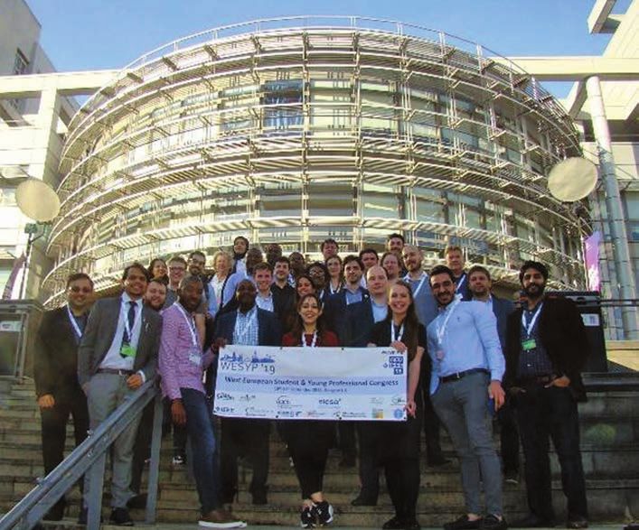
Surface temperature T (°C)
                                                                                     µm                                                             27.4
                                                                                                                           60 µm
                                                                                      10                                   p-contact   n-contact        27
                                                                                              Laser
    Micro-transfer printing of III-V laser on Si                                                                                                        26
                                                                                       0
                                                                                                                                   Si substrate         25
                                                                                     –10                                                                24
                                                                                           Ridge      2.5 µm
                                                                                     –20   section              Active region                           23
                                                                                                                (2.5 × 0.106) µm2
                                                                                     –30                                                                22
                                                                                           InP
    InP Substrate     InP Substrate                Si Substrate     Si Substrate                                 1.615 µm                               21
                                                                                     –40
                       Pick-Up        Transfer      Print         Anchor removal            Si substrate                                                20
                                                                                        –60           –40      –20           0          20         µm
                                          (a)                                                                        (b)

Figure 4. (a) Schematic illustration of the micro-transfer printing process for fabrication of InP-based III-V lasers on Si substrates.
The devices are collected from the original InP substrate using a polydimethylsiloxane stamp and transferred to the target Si sub-
strate. (b) Cross-section of the simulated temperature profile of an InP-based laser printed onto an Si substrate, demonstrating re-
duced thermal impedance compared to lasers on both InP and Si-on-insulator substrates [9].

the formation of threading dislocations and delivering smooth               etching a trench in the wafer to the underlying handle. The III-V
interfaces between layers. Additional work is required to op-               gain medium can then be integrated using transfer printing
timise these devices, but measurements on recently grown                    (illustrated schematically in Fig. 4(a)).
prototype devices already display impressive characteristics,                   The transfer printing approach has a particular advantage in
including low threshold current density (~150 A cm–2) and                   that the III-V laser then sits directly on the silicon substrate,
weak temperature dependence of the differential (slope) ef-                 with the higher thermal conductivity of silicon providing good
ficiency, suggesting reduction or elimination of IVBA. With                 heat dissipation. Recently, following such an approach, we
these results the time is now ripe to re-appraise metamorphic               have demonstrated that 500 mm long ridge waveguide lasers
heterostructures, not just for telecom lasers but also for a host           micro-transfer-printed onto a silicon substrate have a thermal
of wider potential applications.                                            impedance of 38 K W–1, compared to 57 K W–1 on the native
                                                                            InP substrate, and 94 K W–1 when printed on a silicon-on-
5. Transfer Printing and Photonic                                           insulator substrate [9].
Integrated Circuits
Currently, the largest emerging application area for III-V tele-            6. Outlook
com lasers is in silicon-based PICs, for applications in high-              Despite their ubiquity in optical communications, telecom
bandwidth, short-haul data transmission in data centres. PICs               lasers continue to present key challenges spanning funda-
are desirable from a practical perspective due to the capability            mental physics, materials growth and processing, and device
to integrate high performance and rich functionality in devices             engineering. InP-based devices currently reign supreme, but
having small footprint. However, the challenges that must be                have undoubted limitations. Following the improvements
overcome to guarantee high performance laser operation are                  brought about by the adoption of strained-layer QW lasers,
increased further in PICs. In particular, waste heat dissipation            subsequent improvements in performance have largely been
and instabilities driven by optical feedback become potential-              incremental. The continuing exponential growth of the in-
ly serious issues. Lasers suitable for on-chip integration must             ternet and optical communications, as well as the move to-
therefore address these issues, in addition to the intrinsic loss           wards PICs is driving the demand for devices with improved
mechanisms described above.                                                 characteristics, including improved efficiency, reduced tem-
    At present, numerous approaches are being pursued to                    perature sensitivity, and reduced sensitivity to feedback.
mitigate these issues. Lasers can be externally coupled to sili-            With the reduced feedback sensitivity of GaAs-based QD
con-on-insulator based PICs using surface gratings, or can be               lasers and the promising reduced temperature sensitivity ob-
integrated via butt coupling using “flip-chip” bonding. Such                served in recent prototype metamorphic lasers, we believe
coupling schemes are performed at individual device level, or               that such devices should have a significant role to play in
in a one-dimensional array of devices, resulting in costly pack-            satisfying the ever-growing demands of future communica-
aging. More promising then are techniques by which a III-V                  tion systems.
gain medium can be directly integrated on-chip in a scalable
manner such as III-V growth on silicon, wafer bonding and                   Acknowledgements
substrate removal, or transfer printing. These latter approaches            The authors acknowledge the support of Science Foundation
allow the laser cavity to be engineered on-chip, with coupling              Ireland (SFI; via the Irish Photonic Integration Centre, and via
between the silicon waveguide and III-V gain medium pro-                    project. no 15/IA/3082) and the National University of Ireland
vided via tapered waveguide sections. A butt coupling between               (NUI; via the Post-Doctoral Fellowship in the Sciences, held
the III-V waveguide and silicon waveguide is implemented by                 by C.A.B.).

8         IEEE PHOTONICS SOCIETY NEWSLETTER                                                                                             February 2020
References [6] “Electrically pumped continuous-wave III-V quantum dot la-
[1] “73% CW power conversion efficiency at 50 W from 970 nm diode sers on silicon”, S. Chen, W. Li, J. Wu, Q. Jiang, M. Tang,
laser bars”, M. Kanskar, T. Earles, T. J. Goodnough, E. Stiers, S. Shutts, S. N. Elliot, A. Sobiesierski, A. J. Seeds, I.
D. Botez, and L. J. Mawst, Electron. Lett. 41, 245 (2005). Ross, P. M. Smowton, and. H. Liu, Nature Photonics 10,
[2] “The temperature dependence of 1.3- and 1.55-μm compressively 307 (2016).
strained InGaAs(P) MQW lasers”, A. F. Phillips, S. J. Swee- [7] “Band engineering in dilute nitride and bismide semiconductor
ney, A. R. Adams, and P. J. A. Thijs, IEEE J. Sel. Topics lasers”, C. A. Broderick, M. Usman, S. J. Sweeney, and E.
Quantum Electron. 5, 401 (1999). P. O’Reilly, Semicond. Sci. Technol. 27, 094011 (2012).
[3] “Band-structure engineering for low-threshold high-efficiency semi- [8] “Theory and optimization of 1.3 μm metamorphic quantum well
conductor lasers”, A. R. Adams, Electron. Lett. 22, 249 (1986). lasers”, S. Bogusevschi, C. A. Broderick, and E. P. O’Reilly,
[4] “Reduction of laser threshold current density by lowering the IEEE J. Quantum Electron. 52, 2500111 (2016).
valence band effective mass”, E. Yablonovitch and E. Kane, [9] “Thermal analysis of InP lasers transfer printed to silicon pho-
IEEE J. Lightwave Tech. 4, 504 (1986). tonics substrates”, R. Loi, J. O’Callaghan, B. Roycroft, Z.
[5] “The impact of strained layers on current and emerging semicon- Quan, K. Thomas, A. Gocalinska, E. Pelucchi, A. J. Trin-
ductor laser systems”, S. J. Sweeney, T. D. Eales, and A. R. dade, C. A. Bower, and B. Corbett, IEEE J. Lightwave Tech.
Adams, J. Appl. Phys. 125, 082538 (2019). 36, 5935 (2018).
Got News?
We want to hear from you!
Want to recognize a
colleague, attended
a conference or had
a great event
sponsored by the
Photonics Society?
Contact us at
IPSNEWSLETTER@IEEE.ORG
IEEE Photonics Society News
February 2020 IEEE PHOTONICS SOCIETY NEWSLETTER 9Industry Engagement
Life at a Photonics Startup: Lessons Learned
Topic: Project Management
A regular column by Daniel Renner
About the Column the market. I am looking forward to the regular conversation
This is a regular column that explores business aspects of tech- to be carried out through this column!
nology-oriented companies and in particular, the demanding
business aspects of photonics startups. The column touches The Basics of Project Management
on topics such as financing, business plan, product develop- Many years ago, I heard someone mention that the Empire
ment methodology, program management, hiring and reten- State Building, the iconic skyscraper in New York City, was
tion, sales methodology and risk management. That is to say, built in a little over thirteen months. This really surprised me!
we include all the pains and successes of living the photonics I found it hard to believe that such a massive structure could
startup life. be built in such a relatively short period of time! I checked this
This column is written sometimes by me (Daniel Renner) information as soon as I could and indeed, construction on the
and sometimes by invited participants, so that we can share Empire State Building (ESB) started on March 17th, 1930 and
multiple points of view coming from the full spectrum of indi- the building was officially opened for occupancy thirteen and
viduals that have something to say on this topic. At the same a half months later, on May 1st, 1931. The ESB was planned
time, this is a conversation with you, the reader. We welcome to be the world’s tallest building at that time, title that it held
questions, other opinions and suggestions for specific topics to for more than 40 years! The ESB still holds the record for sky-
be addressed in the future. scraper rate of construction! The ESB construction rate was
The expectation is that this column will turn into a useful
source of business-related information for those who intend to
start, join, improve the operation, fund, acquire or sell a pho-
tonic startup. A fascinating area that I have been one of those
lucky to enjoy as a way of living for a long time.
A Bit About Me
I grew up in the wilderness of Chilean
Patagonia, a fact that is one of the ori-
gins of my quest for adventure and for
exploring new areas. In my early twen-
ties, I decided to leave the Patagonian
open spaces for high-tech open fields. I
went to the University of Cambridge
in England to do a Ph.D. in Opto-
Electronics, a brand new area at the
time. Now, decades later, I have lived through the whole range
of experiences that relate to the development, manufacturing
and commercialization of complex photonic devices and sys-
tems used in communication, sensor and industrial applica-
tions. My experience spans both the technical and the commer-
cialization aspects of photonic products, with activities within
DANIEL ACKER/BLOOMBERG/GETTY IMAGES
many aspects, including technology and product development,
identification of new business areas, introduction of new prod-
ucts, marketing and sales. This experience has included both
large and small companies, which gives me a reasonable van-
tage point to comment on the ups and downs of life in a pho-
tonics startup.
I am currently Chief Business Development Officer at Free-
dom Photonics, Santa Barbara, CA, where I am responsible
for the identification of new business areas, definition of new
products and the successful introduction of these products into Aerial view of the Empire State Building in New York City.
10 IEEE PHOTONICS SOCIETY NEWSLETTER February 202087 floors per year, which is the fastest of any skyscraper ever Smith talked to his good friend John J. Raskob about the proj-
built, including the newer ones. Typical construction rates for ect. John Raskob was a self-made millionaire. He had worked
modern skyscrapers (built since 1980) is 12 to 35 floors per year. as an adviser for Pierre S. du Pont and they jointly made signif-
In addition, the construction project was completed under icant investments in General Motors (GM) stock. Through in-
budget. What were the key elements that made the ESB proj- telligent investing, Pierre du Pont became GM chairman, with
ect so successful? This sounds like a good case study to identify Raskob his vice president. Raskob created General Motors Ac-
the basics of effective Project Management. In this article we ceptance Corporation (GMAC), and through this credit arm
will extract from this case study the lessons that form the foun- of GM he revolutionized the way people bought automobiles.
dation for successfully managing a project. There is plenty of Following his successful time at GM, John Raskob became
public information about how the ESB was built and, for this the Chairman of the Democratic National Committee, where
article, I have retraced the project story mainly through the the two men initially met and became good friends given the
accounts found in the books and papers included in the list of strong similarities in their cultural background and political
references at the end of this article. views. John Raskob was also looking at that time for an inter-
esting transcendent venture for himself. From his time at GM,
The Lessons learned for effective Project Management are Raskob was highly competitive with Walter Chrysler, who had
inserted at appropriate points in the story in text boxes started constructing a skyscraper to house the offices of his cor-
like this. poration. Raskob wanted a building that would literally and
figuratively put Walter Chrysler’s building in the shade. So,
The seminal idea to build the ESB most likely came from both Al Smith and John Raskob had a great urge to show the
Alfred E. Smith, who had been Governor of New York from world that their ability to create was not finished, in fact, far
1923 to 1928. He did not seek reelection as Governor in 1928 from it. They would build the tallest building ever created,
to focus on the Presidential campaign, for which he was the for which Al Smith would bring his political connections and
Democratic Party candidate. Eventually, he lost the Presiden- public relations abilities and John Raskob would bring fund-
tial election to Herbert Hoover. So, by the beginning of 1929, ing for the enterprise, through his friends, financial institu-
Al Smith was feeling somewhat despondent and searching for tions and himself.
a new destiny. From these emotional depths, he came up with On August 29, 1929, former Governor Al Smith announced
the idea of constructing the tallest building in the world in his the creation of a company that would build a thousand-foot-
beloved New York City, he was a New Yorker at heart. That high eighty-story office building–the tallest building in the
would be his new path to notoriety, he would be the creator world. It would occupy more than two acres of land. It would
of the building that would become the very icon of the City. house more than sixty thousand people at one time. As presi-
Given his strong political background, he was well connected dent of the company, Smith would be in full executive con-
in the City and knew what was needed to make such a grand trol and front man. The front-page headline in The Times the
project happen. He coined the name Empire State Building, to following day was: SMITH TO HELP BUILD HIGHEST
honor and give global recognition to the nickname of the state SKYSCRAPER. His was the glory, his was the majesty that
that he loved so much. Sometime in the spring of 1929, Al brought recognition and power to the undertaking.
Photographs of the Empire State Building under construction, taken over a period of four and a half months!
February 2020 IEEE PHOTONICS SOCIETY NEWSLETTER 11In September 1929, the Empire State Building Corporation
rented space for its executive offices at 200 Madison Avenue, Lesson # 3: Keep the design as simple as possible. It is
not far from the construction site. The architectural firm of dangerous to fall in love with the technology and lose sight
Shreve & Lamb was retained as the ESB architects on Septem- of the business. Minimize risk by only introducing new
ber 9, 1929. Raskob knew the work of the firm well, he had elements that are absolutely necessary to meet project ob-
been part of the planning group for the General Motors Build- jectives. This was one of the fundamental factors in the
ings at Columbus Circle, which had been designed by Rich- ESB project success. You can find additional information
mond Shreve and William Lamb extraordinarily well. Shreve & on Risk Management in the December 2019 issue of this
Lamb were the prime skyscraper architects in New York at that column (IEEE Photonics Society News, vol. 33, No. 6).
time. Shreve’s genius was organizational and Lamb’s in design.
Shortly after their appointment, Shreve said: “Our plan is to William Starrett said that the builder of a skyscraper could
find the best available brains in the real estate field, in various be compared to the general of an army. For the builder must
branches of engineering, in architecture, building and labor. lead and inspire the thousands of men whose united labor re-
Then we will put our ideas on the table. The best of the ideas sults in a mighty structure; he must control his sources of sup-
we develop in this fashion are the ones we will use.” Raskob ply; and he must see that his “supply trains” keep pace with
insisted that the building would open on May 1, 1931, in well his need for them.
under two years. He was bold enough to inform the Governor
of New York, Franklin D. Roosevelt, to mark that date on his Lesson # 4: There has to be one and only one overall Proj-
calendar, and with that, Shreve and Lamb went to work. ect Manager (Army General). The role of Project Manager
Less than two weeks later, September 21, 1929, the builders (PM) can be held by different people at different points
were selected, Starrett Bros and Eken, arguably the standard in the project, for example, first someone from Marketing,
bearer for the industry, greatest building contractors of their then from Design and then from Manufacturing, but at any
day. Paul Starrett was in charge of negotiations. William Star- point there can be only one overall PM. Likewise, all other
rett and Andrew Eken managed day-to-day affairs at construc- roles and responsibilities in the project should be clear.
tion sites. Eken became known as the “dean of the American
skyline builders.” Prior to the ESB project, they already had a At this point, early fall of 1929, the Chrysler Building and
series of construction speed records. There were few firms com- the Bank of Manhattan Building were ostensibly in a race with
parable to Starrett Bros. and Eken within the industry, in their each other. By October 1929, it was clear that the Chrysler
ability to plan and execute a large project. Building was going to be seventy-seven stories and 1,048 feet
Al Smith, John Raskob and the architects knew that it was with the erection of a stainless-steel spire. Raskob told the ar-
wise to have a general contractor with whom to consult as early chitects to go back to the drawing boards and design a build-
as possible. A policy working group on design and construc- ing bigger than Chrysler’s.
tion was established straightaway and the basic plan for the In November 1929, Al Smith announced that the ESB
building was reached in just four weeks. “The logic of the plan would not after all, be only eighty stories high. It would be
was very simple,” said Lamb in 1931 in The Architectural Fo- eighty-five stories, or 1,050 feet, two feet taller than the tip
rum. He recycled in this plan significant elements from pre- of the useless spire adorning the Chrysler Building. The ESB’s
vious projects. Two new technology improvements were in- observation deck would be on the roof of the eighty-fifth floor,
corporated, which were necessary to achieve the extraordinary the equivalent of the eighty-sixth floor, more than 150 feet
building height: thinner, lighter and stronger structural steel higher than the Chrysler’s observatory. Estimates for construc-
and high-speed elevators. These new aspects were absolutely tion were $35M.
necessary for the project to achieve its objective. Otherwise, Then, on December 11, 1929, Al Smith announced the news
the architects tried to maintain as simple and conventional a that the ESB would not be the tallest building in the world by
design approach as possible. a mere two feet. It would be the world’s tallest building by 202
feet, rising to the astonishing height of 1,250 feet. “Building
Lesson # 1: Incorporate all functions that will execute the with an eye to the future,” said Smith, the building would
project right from the beginning, even if their active par- be topped by a dirigible mooring mast that could accommo-
ticipation will not come until later. There is enormous date passengers for the already existing transatlantic routes,
value to hear a wide range of opinions during the initial and for routes planned to South America, the West Coast and
planning phase. across the Pacific. An elevator would travel the 167 feet from
the observation deck on the eighty-sixth floor to the totally
glassed-in observation level on the 101st floor, a circular room
thirty-three feet in diameter, where windows would provide
Lesson # 2: Form a team that includes the best possible
unobstructed views. Above this room and reached by a stair-
people. The product generated by a team of highly intel-
way would be the 102nd floor observatory, this one twenty-five
ligent and talented individuals is what will distinguish
feet in diameter. The cylindrical structure was surmounted by
your project and company from the competition. Surround
a conical dome whose tip was 1,250 feet above the sidewalk.
yourself with the best talent that you can find. Good people
The primary purpose of the platform, however, was to serve as
will make a big difference!
the boarding area for the anticipated dirigible passengers.
12 IEEE PHOTONICS SOCIETY NEWSLETTER February 2020Gantt Chart used in planning and tracking the Empire State
IMAGNO/GETTY IMAGES
Building construction.
The additional job was estimated at about $750,000, a paltry
2 percent addition to the final costs. It was a small price to pay
to ensure the building its title. The dirigible mast was never Construction worker on the Empire State Building with the
used for its original intended purpose but was extremely useful Chrysler Building in the background.
to broadcast television.
Lesson # 5: On many occasions the Project Objectives are
not 100% clear at the time of project launch. This is fine, Lesson # 6: Having clear project objectives, detailed design
it is part of what the initial planning phase should handle can be done in parallel with other project tasks. Maximize
and convert “fuzzy” objectives into crystal clear ones. The the utilization of parallel task opportunities, rather than
project team should note those objectives that are clear and sequential execution.
those that need further evaluation. Spend as much effort as
necessary to define a full set of clear objectives by the end The question facing the builders before they started was
of the planning phase. The initial planning effort should whether to manage this job by decentralization or centraliza-
provide a balance between project objectives, resources and tion. If centralized, the contractor used a large staff of expedit-
schedule. Following completion of the project plan, the de- ers to ensure that the jobs were done well and on time by the
fined objectives should not change (or only under extreme subcontractors. The expertise and initiative of the subcontrac-
circumstances). tors was subordinated to that of the general contractor’s orga-
nization. The decentralized method provided autonomy to the
Driven by the exigencies of the schedule, the designers had subcontractors. It gave them the freedom to put their special-
the draftsmen make drawings from the bottom up. They did ized knowledge and skill to work in getting the job done, in
not worry about designing the eighth floor until the draw- coordinating their own work with the work of the other sub-
ings for the third floor had been completed and sent to the contractors, and with the operation in general. Starrett opted
fabricators. Plans trickled in for a few floors at a time, so as the for the decentralized route, and they did it with remarkable
foundation columns were drying, the steel workers were busy results. Everyone on the job knew that in order to get the job
planning the next stage. Months would pass before the plans done required friendly relations among those engaged in the
for the roof were completed. Shreve later recalled, “There were work. They developed mechanisms to encourage open dialogue
days when the messenger reached Pittsburgh with drawings among the subcontractors to thresh out any problems that
only an hour before the steel mills started rolling the I-beams might be encountered.
we would need a few days later.”
All this work was carefully coordinated. In fact, construc- Lesson # 7: Make sure that decisions are being made at the
tion of the ESB was one of the first significant projects to use lowest possible level.
Gantt charts to plan and track tasks.
February 2020 IEEE PHOTONICS SOCIETY NEWSLETTER 13You can also read