Anderson House Seismic Strengthening Investigations - Summary Report - APPENDIX 1 - Invercargill City Council
←
→
Page content transcription
If your browser does not render page correctly, please read the page content below
APPENDIX 1
                                       A3189945

Project Number: 6-DP444.00

Anderson House Seismic
Strengthening Investigations
14 July 2020                 CONFIDENTIAL

Summary Report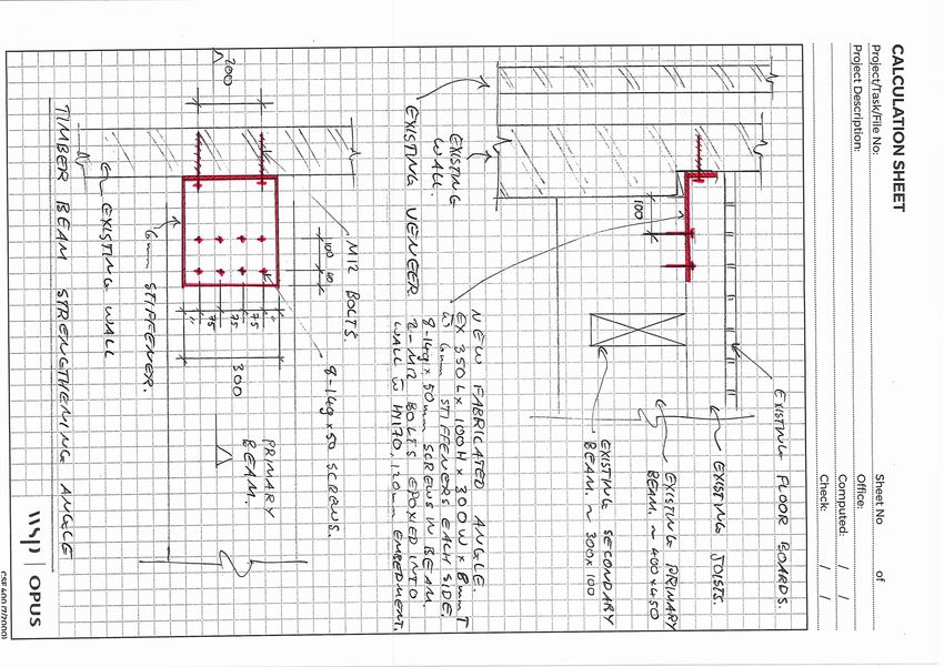
Contact Details

                  Mary Ann Halliday
                  WSP
                  12 Moorhouse Avenue
                  Christchurch 8011
                  +64 3 363 5400

                  Mary.ann.halliday@wsp.com

                  Document Details:
                  Date:          13 July 2020
                  Reference:     6-DP444.00
                  Status:        Draft

                  Prepared by
                  Taylor Green

                  Reviewed by
                  Simon Therkleson

                  Approved for release by
                  Mary Ann Halliday

©WSP New Zealand Limited 2020                   i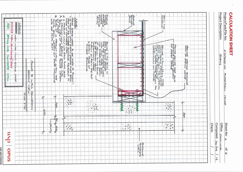
Document History and Status
Revision     Date            Author                Reviewed by        Approved by     Status
A.1          22/06/2020      T. Green,             S. Therkleson      M.A. Halliday   DRAFT
                             M. A. Halliday

Revision Details
  Revision                                               Details
A.1           Draft release for client comment

                                      ©WSP New Zealand Limited 2020                            ii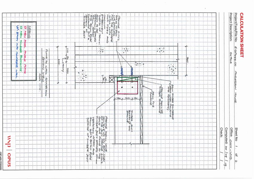
Contents
1   Introduction ......................................................................................................................................................................................................... 1
    1.1          Background ........................................................................................................................................................................................... 1

2   Discussion.............................................................................................................................................................................................................. 2
    2.1          Secondary Timber Beam/Concrete Walls ................................................................................................................... 2
    2.2          Steel Floor Beams ............................................................................................................................................................................ 4
    2.3          Bay Window Floor Beam ...........................................................................................................................................................5
    2.4          Roof Structure.....................................................................................................................................................................................5
    2.5          Chimney.................................................................................................................................................................................................. 6
    2.6          Heritage .................................................................................................................................................................................................... 7

3   Conclusions .......................................................................................................................................................................................................... 7

4   Disclaimers and Limitations ................................................................................................................................................................. 8

                                                                                  ©WSP New Zealand Limited 2020                                                                                                              iii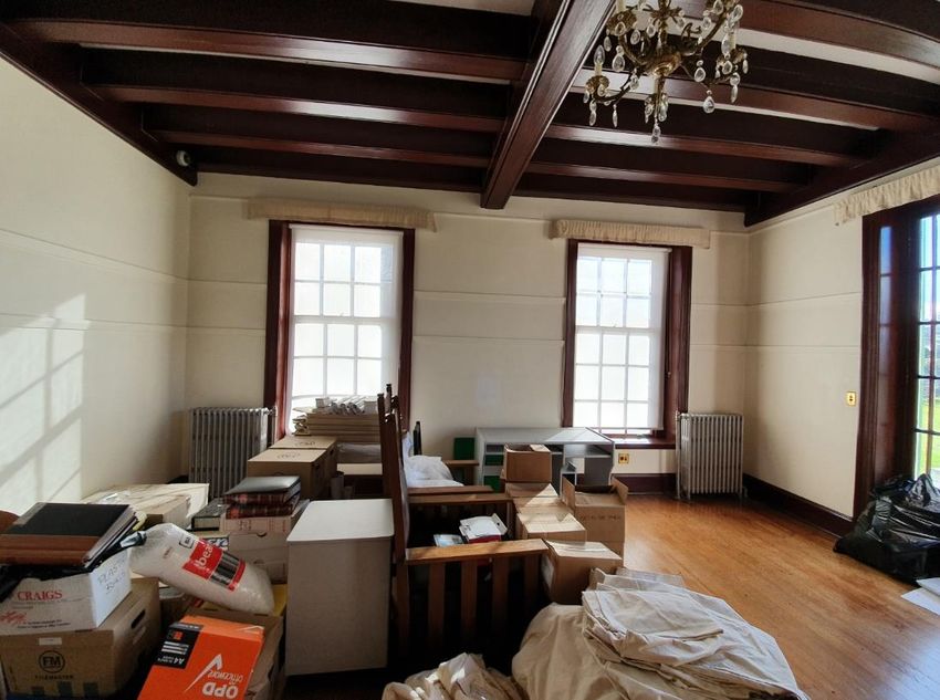
Project Number: 6-DP444.00
Anderson House

1     Introduction
WSP has been engaged by Invercargill City Council to provide professional engineering services for
the investigation and seismic assessment of Anderson House located at Anderson Park, 91 McIvor
Road, Waikiwi.

WSP have previously been engaged to carry out site inspections and prepare a Detailed
Engineering Evaluation (DEE) in January 2014. The reported poor seismic performance led to the
building being closed. A strengthening scheme to 67% NBS (IL2) was prepared and costed at the
time of the evaluation.

WSP has now carried out further investigations and re-assessed the building using techniques that
were not available in 2013, resulting in an increase in the expected seismic performance of select
elements of the building and therefore changing some of the assumptions made in the DEE. The
increase is due to changes in the New Zealand Society for Earthquake Engineering (NZSEE)
assessment guidelines and legislation regarding earthquake prone buildings which have both
been revised since 2014.

1.1    Background
A site visit and visual investigation of the building was completed by WSP with a contractor on the
4th June 2020 to open up key areas requested previously. Careful intrusive investigations were
completed at the specified locations to confirm details that were unclear from the previous work.
Investigations were limited to localised openings in the floor(s), wall(s) and ceilings(s) at first floor
level.

The results of the site investigations indicate the following:

      1      The condition of the concrete work appears to be very good, compared to other
             structures built during this time. It was found that there is reinforcement in the
             concrete which is unusual for a concrete structure of this age. Figure 1 below highlights
             the location of reinforcement (in red) which was identified along the back wall during
             the inspection.
      2      The observed concrete is cast in-situ with clear formwork edges observed. There is no
             evidence to indicate that it is camerated concrete.
      3      The T&G floor condition is very good, with only minor damage where penetrations for
             services have been opened.
      4      The existing floor joists appear to be cast into the concrete walls which provide good
             shear transfer capacity however no ties or other fixings were observed which could
             provide tension capacity.
      5      The chimneys appear to be well confined within the timber floor and roof framing at
             each level and have large concrete arched structures which assist with out of plane
             restraint at each floor level. However, there is only limited support above first floor
             ceiling level, and the chimneys pose a potential fall hazard.
      6      There is one internal concrete dividing wall at first floor level which is supported on the
             timber floor which overloads the floor.
      7      Some of the floor beams vary from what was previously assumed which has a minor
             impact on the strengthening scheme proposed previously.

                                          ©WSP New Zealand Limited 2020                                     1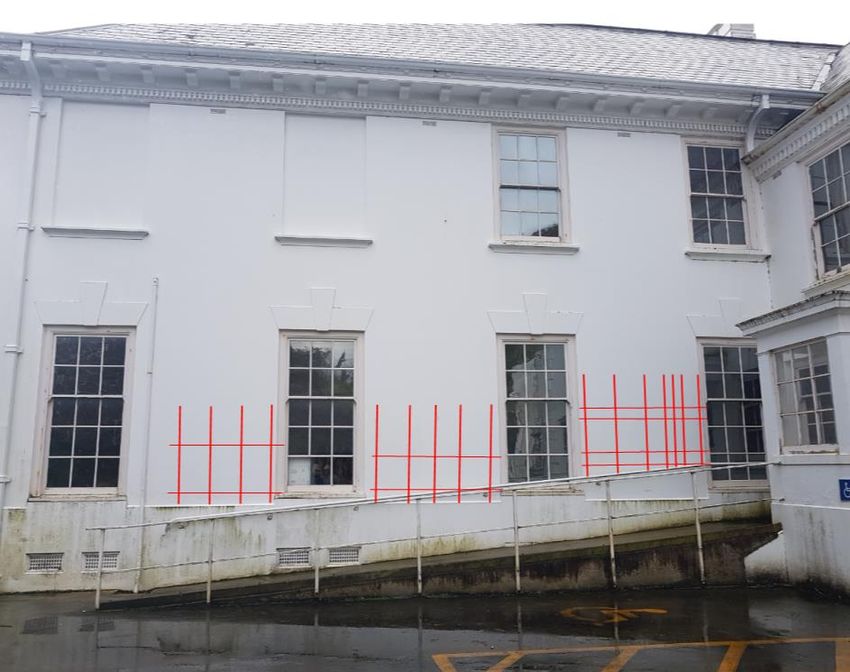
Project Number: 6-DP444.00
Anderson House

          Figure 1: Approximate steel reinforcing in concrete veneer which was
          Identified during the site inspection

2     Discussion
2.1   Secondary Timber Beam/Concrete Walls
The wall between the family room and the Guest room at first floor level is made of concrete.
There is no wall or beam directly underneath. It has been cast on top of the tongue and groove
flooring which is supported on timber floor joists. The ceiling under this floor is quite ornate with
an expressed primary and secondary beam grid system that support the floor joists. An illustration
of the location of the transverse concrete wall with reference to the primary and secondary beams
is presented in Figure 2

Some levels were taken on the floor in the vicinity of the concrete wall. There is a pronounced
displacement of about 15mm. This is depicted Figure 3. Calculations confirm that this
displacement would be expected due to the load from the concrete wall.

The critical member in the flooring system is the secondary beams. The walls impose a large self-
weight (dead load) on the timber flooring which exceeds the calculated capacity of the secondary
beams. Further to this, in an earthquake, the walls impose an additional seismic reaction on the
secondary beams which could require secondary mechanisms to form to support the wall. The
imposed loading on the floor has resulted in a deflection of 15 mm, measured adjacently to one
wall, over the course of the buildings design life.

                                        ©WSP New Zealand Limited 2020                                   2
Project Number: 6-DP444.00
Anderson House

                                                                      Legend

                                                                          First Floor
                                                                          Concrete
                                                                          Wall

                                                                          Primary
                                                                          Beam

                                                                          Secondary
                                                                          Beams

    Figure 2: Location of First Floor Concrete Wall Shown from Ground Floor

          Figure 3: Displacement of Flooring Adjacent to Concrete Wall, Second Storey

                                      ©WSP New Zealand Limited 2020                     3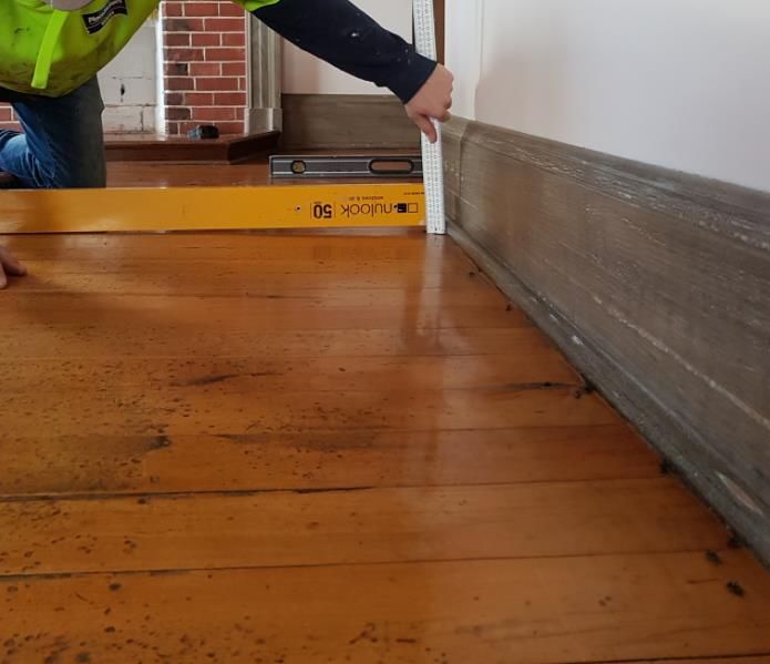
Project Number: 6-DP444.00
Anderson House

                       Table 1: Loading compliance under different load cases

                      Load Case                                     Loading Standard Compliance

            Seismic (Secondary Beam)                                       74% NBS (IL2)

             Gravity (Secondary Beam)                    Live load on floor is limited to 0.31 kPa for code
                                                         compliance. Future uses likely to require 3 kPa.

               Seismic (Timber Joist)                                      57% NBS (IL2)

                Gravity (Timber Joist)                                   Sufficient capacity

An assessment of one concrete wall on the timber flooring was completed to confirm that it was
limiting the overall new build standard percentage (%NBS) for the building. Table 1 shows the
relative NBS percentages for seismic and gravity loading scenarios and indicates that the flooring
system has an overall limit of 57% NBS (IL2). The measured deflection of 15 mm is expected from
the behaviour of timber floors. This deflection is in line with the relative calculated deflection of
19 mm, although, both deflections are significantly over the allowable limit of 10 mm as stated in
the New Zealand loadings standard (AS/NZS 1170.1:2004).

The secondary beams are overloaded in the current condition for basic gravity loading and are not
capable of resisting the minimum usable live load requirements stated in the New Zealand
Building Code.

Strengthening the floor system would require installing new steel beams which will have
significant impact on the heritage fabric. The preferred structural solution is to remove the
concrete dividing walls and reinstate with a lightweight timber option finished to match the
existing. This would significantly reduce the demand on the floor system and allow the floor to be
used for general purposes. We consider that this is the easiest and most economical solution to
improve the performance of the floor system.

2.2   Steel Floor Beams
There are a range of floor support beams which are visible from ground floor level, however most
of them appear to be boxed in. The revised 67% NBS (IL2) strengthening scheme which was issued
in 2019 before the current 2020 site investigations were based on the assumption that these
beams were boxed in steel sections. The strengthening plans previously recommended have been
updated to match the findings in the 2020 investigations. The first area of change is the floor
beams located in the Billiard Room, which are highlighted in solid blues lines in Figure 4 below.

The investigations have shown that the steel beams in the Billiard Room are cast through the
Gallery wall and protrude on the Gallery side of the wall. The beams appear to be well bonded to
the wall and are considered to have sufficient pull out capacity to not require any additional
strengthening.

The tie beams across the Gallery are confirmed to be reinforced concrete sections. There is no
evidence of cracking at the interface with the Gallery walls which indicates that they are reinforced
with ties extending into the concrete walls on each side. These are considered acceptable to
transfer the external wall demands into the building without further strengthening.

                                         ©WSP New Zealand Limited 2020                                        4
Project Number: 6-DP444.00
Anderson House
Legend
Existing steel
beams
Existing concrete
beams
Existing timber
beam
Figure 4: First floor plan of Anderson House with floor beams highlighted
2.3 Bay Window Floor Beam
There is an existing timber floor beam in the middle of the Bay Window area highlighted in red in
Figure 4 which was previously unconfirmed. It was expected that there were steel beams in this
area extending from the end of the highlighted blue beams. The existing timber beam requires
strengthening of the end connections to ensure adequate capacity to achieve 67% NBS (IL2).
In addition, due to the existing beam being in the centre of the curve, further strengthening of the
external wall on each side is required to reduce the span of the external wall. This will use the
same methodology proposed for other areas with additional ties and timber blocking within the
floor void.
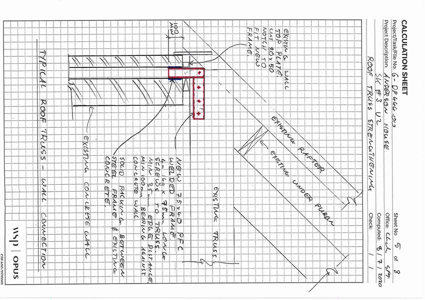
2.4 Roof Structure
The site investigation were not able to observe an adequate connection between the roof
structure (i.e. roof trusses) and the external concrete walls. This means that in an earthquake, the
external walls are not restrained by the roof and the roof load is unable to be transferred down the
structure.
Strengthening of the connection is relatively simple and will involve a fabricated steel bracket
being installed at the end of each truss along the perimeter of the building to provide a lateral
connection between the concrete walls and the roof trusses.
©WSP New Zealand Limited 2020 5Project Number: 6-DP444.00
Anderson House
2.5 Chimney
There are currently four large brick chimneys around the building as highlighted in Figure 5 below.
Two of these are located in the main wing and appear to be similar in terms of size and
arrangement (1 and 2 in figure). The others are in the rear wing with one large chimney against the
back wall, and the other small and slender chimney on the side of the rear wing (3 and 4 in figure).
2 1
3
4
Figure 5: Plan Layout of Anderson House with Floor Beams Highlighted
Chimneys 1 and 2 in the main wing were found to be structurally sound below first floor ceiling
level and are well tied into the adjacent timber framing. Above ceiling level, the large mass of the
bricks are not as well restrained and pose a fall hazard. Should either of these chimneys collapse in
a seismic event, they would cause significant damage to the heritage fabric of the building in
addition to the life safety risk associated with falling bricks.
It is recommended that both Chimney 1 in the master bedroom and Chimney 2 in the family
bedroom, be demolished down to first floor ceiling level and be replaced with a lightweight
timber framed structure with lightweight plaster façade cladding. The timber structure is a cost-
effective method to reduce the mass, while providing a plaster cladding system allows it to be
shaped to maintain the heritage appearance and architectural aesthetic of the building.
Chimney 3 and Chimney 4 are located away from the apex of the roof nearer to the external walls
while extending to the same height as Chimneys 1 and 2. This means that they both extend much
further beyond the roof line and have effectively no restraint above first floor ceiling level.
It is recommended that chimneys 3 and 4 should be demolished down to first floor ceiling and
not replaced. Due to the geometry of these chimneys a steel frame extending from at least first
floor level would be required to reinstate them. This is achievable however we query whether the
additional cost is warranted. We do not consider that these chimneys have the same heritage
©WSP New Zealand Limited 2020 6Project Number: 6-DP444.00
Anderson House
value as Chimneys 1 and 2 and recommend that this proposal is discussed further with the
heritage consultants and affected parties prior to acceptance.
2.6 Heritage
Anderson Park House is listed with Heritage New Zealand. All proposed works would require a
resource consent which would include comment from Heritage New Zealand. The structural
proposals recommended in this summary are simply the most expedient. We understand that
previous discussions have included the idea of lightweight chimneys. The chimneys in the main
part of the house can be reconstructed in timber to look like the existing relatively easily. This may
also alleviate some of the problems in the area with water proofing. The idea of completely
removing the chimneys to the south (3 and 4) may not be acceptable. However, the cost to keep
these may exceed the cost of all the other strengthening work. In order for all parties to appreciate
the variables the best way forward may be to have collaborative discussions before a decision is
made regarding these chimneys.
3 Conclusions
WSP have carried out further site investigations in 2020 which have reinforced our opinion that
the existing Anderson House is generally an extremely well-constructed building for the age and
construction form with only local elements which do not perform adequately for modern seismic
design procedures. The localised issues include the following:
1 The existing internal concrete dividing wall between the Family and Guest rooms. This
concrete wall has been constructed on the suspended timber floor and overloads the floor
beyond its acceptable capacity under self-weight gravity loads alone.
2 The floor to concrete wall connections around the perimeter in some areas, are insufficient
to restrain the external concrete walls out of plane.
3 There does not appear to be a reliable connection to transfer seismic loads between the
existing timber roof structure and external concrete walls.
4 The existing brick chimneys pose a fall hazard especially in the rear wing.
WSP have prepared a revised strengthening scheme to address the issues identified, which has
been designed to achieve 67% NBS (IL2). This scheme is attached in Appendix A of this report.
The scheme has been developed to best utilise the existing heritage elements, with only minimal
impact on the high value timber flooring and other irreplaceable features. The design has been
developed using sketches and mark-ups of available documentation to allow for further
modifications should these be necessary to accommodate resource consent and future use
requirements. We consider that this scheme can be best implemented in a practical manner with
a competent contractor as it is expected that it will be necessary to adjust some details to suit
individual conditions on site.
It is recommended that a Heritage Consultant be engaged to prepare a Conservation Plan and to
provide input to the final design for the chimneys.
©WSP New Zealand Limited 2020 7Project Number: 6-DP444.00
Anderson House
4 Disclaimers and Limitations
This report (‘Report’) has been prepared by WSP exclusively for Invercargill City Council (‘Client’) in
relation to Anderson House Seismic Strengthening (‘Purpose’) and in accordance with the Short
form Agreement with the Client dated 17 January 2020. The findings in this Report are based on
and are subject to the assumptions specified in the Report and in the Offer of Services dated 17
January 2020]. WSP accepts no liability whatsoever for any reliance on or use of this Report, in
whole or in part, for any use or purpose other than the Purpose or any use or reliance on the
Report by any third party.
In preparing the Report, WSP has relied upon data, surveys, analyses, designs, plans and other
information (‘Client Data’) provided by or on behalf of the Client. Except as otherwise stated in the
Report, WSP has not verified the accuracy or completeness of the Client Data. To the extent that
the statements, opinions, facts, information, conclusions and/or recommendations in this Report
are based in whole or part on the Client Data, those conclusions are contingent upon the accuracy
and completeness of the Client Data. WSP will not be liable in relation to incorrect conclusions or
findings in the Report should any Client Data be incorrect or have been concealed, withheld,
misrepresented or otherwise not fully disclosed to WSP.
©WSP New Zealand Limited 2020 8Appendix A 67% NBS (IL2) Seismic Strengthening Scheme Note: The ‘letter’ of the Appendix is an automatic number, so you if you copy and paste the table, the ‘letter’ will automatically change.
wsp.com/nz
Timber beam requires strengthening
                                                                            Timber beam requires
    with 2-M12 anchors into wall & 8-14g
                                                                            strengthening of end connection
    x 50mm long screws into timber
                                                                            similar to joist strengthening detail.
    beam through fabricated steel angle.
                                                                            See Sk01.
    See Sk04.

               1              2                   3                     4            5                    6          7

A

B

                                                                                                                                 LEGEND

                                                            Dickison Room                                                        (E) Floor Support Beam
                      Latham Room                                                                       Hewat Room

C                                                                                                                                (E) Floor Joist Span Direction

                                                                                                                                 (N) 50x0.91mm Multibrace
                        Jenkin Room
                                                                                                                                 Strap extending 1.5m into room
                                                                                                                                 as per detail Sk02.

                                                                                                                                 (N) Additional 10g-65mm long
D                                                                                                                                screw through floorboard to
                                                                                                                                 every third joist adjacent to wall.

                                                                                                                                 (N) Joist to Wall Connection
                                                                                                                                 improved as per detail Sk01.

                                                                                                                                 (N) Improve Connection as per
E
                                                                                                                                 detail Sk04.

                                                                                                                                 (N) Remove existing concrete
                                                                                                                                 wall and replace with lightweight
                                                                                                                                 timber to suit if required.
Coke breeze wall at first floor level only. Spans over
timber floor framing.
Existing floor framing is overloaded under gravity
load and additional seismic demand reduces
reliability in the floor capacity. In addition, the floor
system changes within this area complicating the
load paths to transfer the demand back to chimney
buttress.                                                        F
                                                                                                                         DOCUMENT CONTROL
Removal of the breeze wall is recommended,
alternatively, strengthening of the connections across
                                                                                                                         Date: 26 July 2020 Rev. 2
the wall is required including strengthening of the
connection to the chimney buttress.
                                                                                                                         Sheet No.   1   of   8

                                                                                                                         Status: Developed Design

                                                                 G                                                       By: S. Therkleson (WSP)

                                                                                                                         Comments: NOT FOR CONSTRUCTION
         First Floor Plan 67% NBS (IL2) Strengthening
1 2 3 4 5 6 7
A
B
LEGEND
(E) Roof Truss
C (E) Under Purlin with rafters
over.
(N) Demolish existing Chimney
down to first floor ceiling level.
Replace with 90x45 Hyspan
framed chimney with lightweight
D Integra Facade system on
20mm cavity battens over
19mm plywood. Connections to
existing to be confirmed once
demolition of brickwork is
complete.
E
(N) Improve Connection as per
details. See Sk03.
Typical Truss Strengthening to comprise 75x40 PFC
fabricated U bracket with 4-14g-50mm long screws into
truss. Provide solid packing between PFC and existing
concrete wall and internal face of veneer. See Sk03.
New timber frame to extend down to first floor ceiling level.
Provide 90x90 hyspan chords in each corner with 90x45 SG8
timber framing at 400mm centres between.
Line with 19mm plywood fixed to timber framing with 2 rows of
3.15x50mm long flat head nails at 50mm centres each around DOCUMENT CONTROL
perimeter and at 200mm centres internally.
Fix timber framing to top of existing brickwork with steel angle Date: 26 July 2020 Rev. 2
brackets with 2-M12 threaded rods with 450mm embedment
with Hilti HY-170 epoxy. Sheet No. 2 of 8
Refer to example drawing of Resene Integra Facade System
for cladding details with the surface finish sized, moulded and Status: Developed Design
coloured to match the existing chimney.
See Sk05. By: S. Therkleson (WSP)
Comments: NOT FOR CONSTRUCTION
Roof Plan 67% NBS (IL2) Strengthening3 8
Chch NND
Developed Design 20 / 06 / 2020
NOT FOR CONSTRUCTION4 8
Chch NND
Developed Design 20 06 2020
NOT FOR CONSTRUCTION
5. Strap can be installed to either the top or bottom face
of the floor joists to reduce impact on heritage fabric.6-DP444.00 Anderson House 6 8 SK #04 Chch SPT Developed Design 19 06 2020 NOT FOR CONSTRUCTION
C
FR HIM
  AM N
        E
     IN Y
       G EX
         N A
          O M
           T P
            FO LE
              R -I
               TH NT
                  IS ER
                    PR N
                      O LA
                       JE
                         C
                           T
      2.77 m
                3.26 m
1 2 1 2
3
3
4
4
Demolition PlanYou can also read