Användarhandbok S Handleiding N Handbuch D - Manual E Manuel F Manual E - Victron Energy
←
→
Page content transcription
If your browser does not render page correctly, please read the page content below

Manual

                                             EN
                               Handleiding

                                             NL
                                   Manuel

                                             FR
                                Handbuch

                                             DE
                                   Manual

                                             ES
                          Användarhandbok

                                             SE

smallBMS with pre-alarm

1. General Description

                                                                                                                                         EN
A simple and low cost alternative to the VE.Bus BMS
The smallBMS can replace the VE.Bus BMS in several applications. It is however not suitable for use with VE.Bus MultiPlus and
Quattro inverter/chargers: it has no VE.Bus interface.

                                                                                                                                         NL
The smallBMS is intended for use with Victron Smart LiFePo4 batteries with M8 circular connectors.
The smallBMS has three outputs, similar to the VE.Bus.BMS.

Load Disconnect output

                                                                                                                                         FR
The Load output is normally high and becomes free floating in case of imminent cell under voltage voltage (default 2,8V/cell,
adjustable on the battery between 2,6V and 2,8V per cell). Maximum current: 1A. The Load output is not short-circuit protected.
The Load output can be used to control:
A high current relay or contactor.
The remote on/off input of a BatteryProtect, inverter or DC-DC converter or other loads.

                                                                                                                                         DE
(a non inverting or inverting on/off cable may be required, please consult the manual)

Pre-alarm output
The pre-alarm output is normally free floating and becomes high in case of imminent cell under voltage (default 3,1V/cell,
adjustable on the battery between 2,85V and 3,15V per cell). Maximum current: 1A (not short circuit protected).

                                                                                                                                         ES
The minimum delay between pre-alarm and load disconnect is 30 seconds.

Charge disconnect output
The Charger output is normally high and becomes free floating in case of imminent cell over voltage or over temperature.

                                                                                                                                         SE
Maximum current: 10mA.
The Charger output is not suitable to power an inductive load such as a relay coil.
The Charger output can be used to control:
    •    The remote on/off of a charger.
    •    A Cyrix-Li-Charge relay.
    •    A Cyrix-Li-ct Battery Combiner.

System on/off input
The system on/off input controls both outputs. When off, both outputs will be free floating so that loads and chargers are turned
off.
The System on/off consists of two terminals: Remote L and Remote H.
A remote on/off switch or relay contact can be connected between L and H.
Alternatively, terminal H can be switched to battery plus, or terminal L can be switched to battery minus.

Protects 12V, 24V and 48V systems
Operating voltage range: 8 to 70V DC.

LED indicators
    •    Load ON (blue): Load output high (cell voltage >2.8V, adjustable on the battery).
    •    Temp or OVP (red): Charger output free floating (due to cell over temperature (>50°C), cell under temperature (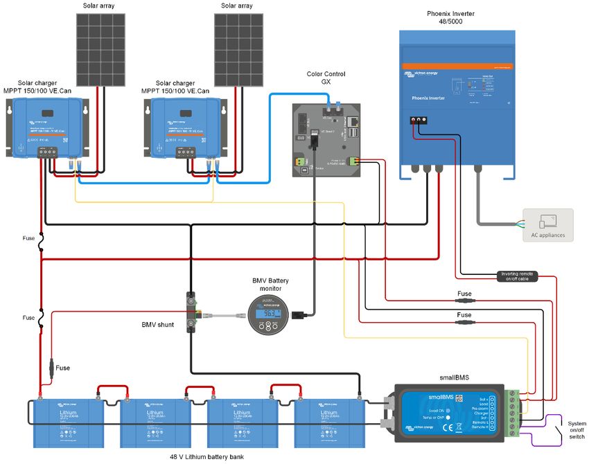
3.3 DC loads with remote on/off terminals
DC loads must be switched off or disconnected in case of imminent cell under voltage.
The Load Disconnect output of the VE.Bus BMS can be used for this purpose.
The Load Disconnect is normally high (equal to battery voltage) and becomes free floating (= open circuit) in case of imminent
cell under voltage (no internal pull down in order to limit residual current consumption in case of low cell voltage).

DC loads with a remote on-off terminal that switches the load on when the terminal is pulled high (to battery plus) and switches it
off when the terminal is left free floating can be controlled directly with the Load Disconnect output.
See appendix for a list of Victron products with this behavior.

For DC loads with a remote on/off terminal that switches the load on when the terminal is pulled low (to battery minus) and
switches it off when the terminal is left free floating, the Inverting remote on-off cable can be used. See appendix.

Note: please check the residual current of the load when in off state. After low cell voltage shutdown a capacity reserve of
approximately 1Ah per 100Ah battery capacity is left in the battery. A residual current of 10mA for example may damage a 200Ah battery
if the system is left in discharged state during more than 8 days.

3.4 DC load: disconnecting the load with a BatteryProtect
A BatteryProtect will disconnect the load when:
input voltage (= battery voltage) has decreased below a preset value, or when
the remote on/off terminal is pulled low. The smallBMS can be used to control the remote on/off terminal

3.5 Charging the LiFePO₄ battery with a battery charger
Battery charging must be reduced or stopped in case of imminent cell over voltage or over temperature.

The Charge Disconnect output of the VE.Bus BMS can be used for this purpose.
The Charge Disconnect is normally high (equal to battery voltage) and switches to open circuit state in case of imminent cell
over voltage.

Battery chargers with a remote on-off terminal that activates the charger when the terminal is pulled high (to battery plus) and
deactivates when the terminal is left free floating can be controlled directly with the Charge Disconnect output.
See appendix for a list of Victron products with this behavior.

Battery chargers with a remote terminal that activates the charger when the terminal is pulled low (to battery minus) and
deactivates when the terminal is left free floating, the Inverting remote on-off cable can be used. See appendix.

Alternatively, a Cyrix-Li-Charge can be used:
The Cyrix-Li-Charge is a unidirectional combiner that inserts in between a battery charger and the LiFePO₄ battery. It will
engage only when charge voltage from a battery charger is present on its charge-side terminal. A control terminal connects to
the Charge Disconnect of the BMS.

3.6 Charging the LiFePO₄ battery with an alternator
See figure 6.
The Cyrix-Li-ct is recommended for this application.
The microprocessor controlled Cyrix-Li-ct includes a timer and voltage trend detection. This will prevent frequent switching due
to a system voltage drop when connecting to a discharged battery.

3.7 Battery
In case of several batteries in parallel and or series configuration, the two M8 circular connector cord sets of each battery should
be connected in series (daisy chained).
Connect the two remaining cords to the BMS.

4. System examples

          Figure 1: Application example for a DC off-grid system, with on/off switch between L and battery negative

2
EN
                                                                                                         NL
                                                                                                         FR
                                                                                                         DE
                                                                                                         ES
Figure 2: Application example for a vehicle or boat, with on/off switch between L and battery negative

                                                                                                         SE

     Figure 3: Application example for a vehicle or boat, with on/off switch between H and L

                                  3
Figure 4: Solar application with two MPPT 150/85 CAN-bus
The MPPT 150/85 CAN-bus has a remote on-off port which can be be controlled directly by the VE.Bus BMS

5. Specifications

smallBMS

Normal operating Input voltage range (Vbat)                                       8 – 70V DC
Current draw, normal operation                            2.2 mA (excluding Load output and Charger output current)
Current draw, low cell voltage                                                      1,2 mA
Current draw, remote off                                                               1,2 mA
                                                                            Normally high (Vbat – 0.1V)
Load output                                                     Source current limit: 1A (not short circuit protected)
                                                                       Sink current: 0A (output free floating)
                                                                            Normally high (Vbat –o.6V)
Charger output                                                  Source current limit: 10mA (short circuit protected)
                                                                       Sink current: 0A (output free floating)
                                                                               Normally free floating
Pre-alarm                                                           In case of alarm: output voltage Vbat -0.1V
                                                             Maximum output current: 1A (not short circuit protected)
                                              Use modes of the system on-off:
                                              a. ON when the L and H terminal are interconnected (switch or relay contact)
System on/off:
                                              b. ON when the L terminal is pulled to battery minus (V< 3.5V)
Remote L and Remote H
                                              c. ON when the H terminal is high (2.9V < VH < Vbat)
                                              d. OFF in all other conditions
                                                          GENERAL
Operating temperature                                                     -20 to +50°C       0 - 120°F
Humidity                                                                 Max. 95% (non-condensing)
Protection grade                                                                     IP20
                                                       ENCLOSURE
Material and colour                                                             ABS, matt black
Weight                                                                               0.1kg
Dimensions (h x w x d)                                                         106 x 42 x 23mm
                                                       STANDARDS
Standards: Safety                                                                 EN 60950
            Emission                                                      EN 61000-6-3, EN 55014-1
            Immunity                                               EN 61000-6-2, EN 61000-6-1, EN 55014-2
            Automotive                                                  Regulation UN/ECE-R10 Rev.4

4
EN
Appendix:

                                                                                                EN
1. Loads which can be controlled directly by the Load Disconnect output of the BMS
Inverters:
All Phoenix inverters VE.Direct

                                                                                                NL
Connect to the left hand terminal of the 2 pole connector
Phoenix 12/800; 24/800; 48/800
Phoenix 12/1200; 24/1200; 48/1200
Connect to the right hand terminal of the 2 pole connector

                                                                                                FR
DC-DC converters:
All Tr type DC-DC converters with remote on/off connector,
and Orion 12/24-20; 24/12-25; 24/12-40; 24/12-70
Connect to terminal H of the 2 pole connector

                                                                                                DE
BatteryProtect and Smart BatteryProtect
Connect to the right hand terminal respectively to terminal H
of the 2 pole connector

                                                                                                ES
Cyrix -Li-Load
Connect to the control input

2. Loads for which an inverting remote on-off cable is needed (article number ASS030550100)

                                                                                                SE
Phoenix 12/180; 24/180; 12/.250; 24/350
All Phoenix VE.Bus inverters rated at 3kVA and more (see fig 4)

3. Solar charge controllers which can be controlled directly by the Charge Disconnect output
BlueSolar MPPT 150/70 and 150/80 CAN-bus
Connect to the left hand terminal of the 2 pole connector (B+)
SmartSolar MPPT 150/45 and higher, Smart Solar MPPT 250/60 and higher
Connect to the right hand terminal (marked + or H) of the 2 pole connector

4. Solar charge controllers for which a VE.Direct non inverting remote on-off cable is needed
(article number ASS030550310)
All BlueSolar models, except the two CAN-bus models BlueSolar MPPT 150/70 and 150/80 CAN-bus

SmartSolar MPPT up to 150/35

5. Battery Chargers
For Skylla TG battery chargers a
Non inverting remote on-off cable is needed
(article number ASS030550200)

For Skylla-i battery chargers a
Skylla-i remote on-off cable is needed
(article number ASS030550400)

Other battery chargers:
Use a Cyrix-Li-Charge

                                             5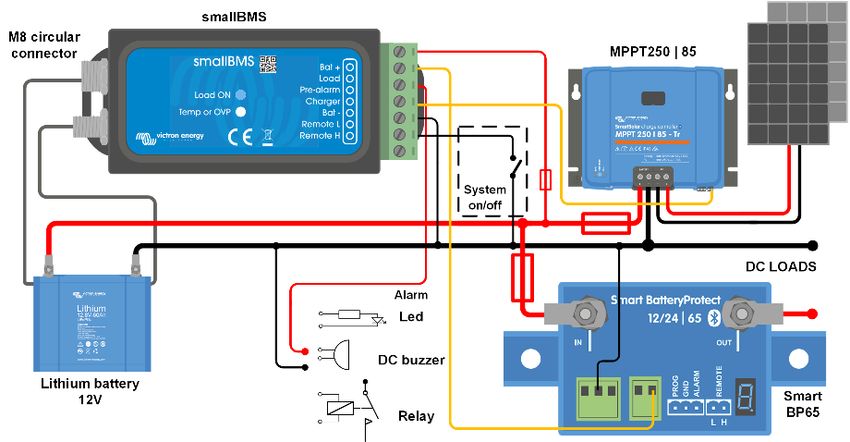

1. Algemene beschrijving

                                                                                                                                                    EN
      Een eenvoudig en goedkoop alternatief voor de VE.Bus BMS
      De smallBMS kan de VE.Bus BMS in verschillende toepassingen vervangen. Het is echter niet geschikt voor gebruik met de VE.Bus
      MultiPlus en Quattro-omvormers/acculaders: het heeft geen VE.Bus-interface.
      De smallBMS is bedoeld voor gebruik met Victron Smart LiFePo4-accu's met ronde M8-contacten.

                                                                                                                                                    NL
      De smallBMS heeft drie uitgangen, vergelijkbaar met de VE.Bus.BMS.

     Lastontkoppelingsuitgang
     De lastuitgang is normaal gesproken hoog en wordt potentiaalvrij in het geval van mogelijke onderspanning van de cel (standaard 2,8
     V/cel, aanpasbaar op de accu tussen de 2,6 V en 2,8 V per cel). Maximale stroom: 1 A. De lastuitgang is niet beveiligd tegen kortsluiting.

                                                                                                                                                    FR
     De lastuitgang kan worden gebruikt om de volgende aspecten te bedienen:
     Een hoogstroomrelais of beveiliging.
     De externe aan/uit-ingang van een accubeveiliging, omvormer of DC-DC-omvormer of andere lasten.
(mogelijk is een niet-omvormende of omvormende aan/uit-kabel nodig, raadpleeg de handleiding)

                                                                                                                                                    DE
      Vooralarmuitgang
       De vooralarmuitgang is normaal gesproken potentiaalvrij en wordt hoog in het geval van mogelijke onderspanning van de cel (standaard
      3,1 V/cel, instelbaar op de accu tussen 2,85 V en 3,15 V per cel). Maximale stroom: 1 A (niet beveiligd tegen kortsluiting)
      De minimale vertraging tussen het vooralarm en de lastontkoppeling is 30 seconden.

                                                                                                                                                    ES
      Laadontkoppelingsuitgang
      De laaduitgang is normaal gesproken hoog en wordt potentiaalvrij in het geval van mogelijke overbelasting van de cel of bij een te hoge
      temperatuur. Maximale stroom: 10 mA.
      De laaduitgang is niet geschikt om een inductieve last te voeden, zoals een relaisspoel.

                                                                                                                                                    SE
      De laaduitgang kan worden gebruikt voor het bedienen van:
           •    De externe aan/uit van een acculader.
           •    Een Cyrix-Li-Charge-relais.
           •    Een Cyrix-Li-ct accucombinatie.

      Systeem aan/uit-ingang
      De aan/uit-ingang van het systeem regelt beide uitgangen. Wanneer beide uitgangen zijn uitgeschakeld zijn beide potentiaalvrij zodat
      lasten en acculaders uitgeschakeld worden.
      De aan/uit van het systeem bestaat uit twee aansluitklemmen: De externe L-klem en de externe H-klem.
      Een externe aan-/uitschakelaar of relaiscontact kan worden aangesloten tussen de L- en H-klemmen.
      Als alternatief, kan de H-klem worden geschakeld naar accuplus of kan L-klem worden omgeschakeld naar de accumin.

      Beschermt 12 V-, 24 V- en 48 V-systemen
      Bedrijfsspanningsbereik: 8 tot 70 V DC.

      LED-indicatoren
          •    Last AAN (blauw): Lastvermogen hoog (celspanning > 2,8 V, aanpasbaar per accu).
          •    Temp of OVP (rood): Laaduitgang potentiaalvrij (door cel-over-temperatuur (>50 °C), cel onder temperatuur (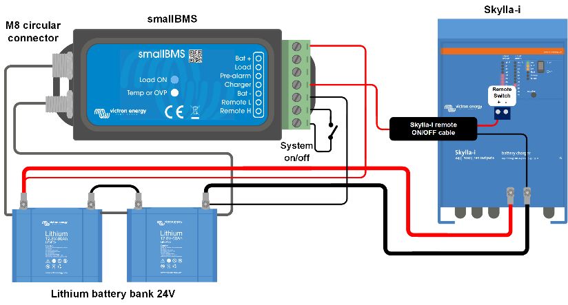
3.3 DC-belastingen met externe aan-/uit terminals
DC-belastingen moeten worden uitgeschakeld of losgekoppeld in geval van dreigende cel-onderspanning.
Hiervoor kan de Lastontkoppelingsuitgang van de VE.Bus BMS worden gebruikt.
De lastontkoppeling is normaal gesproken hoog (gelijk aan de accuspanning) en wordt potentiaalvrij (= open circuit) in geval van
dreigende onderstroom van de cel (geen interne pull-down om het reststroomverbruik te beperken in geval van lage celspanning).
DC-belastingen met een externe aan-uit terminal die de belasting inschakelt wanneer de terminal omhoog wordt getrokken (de accuplus)
en schakelt deze uit wanneer de aansluitklem potentiaalvrij is en kan direct worden bediend met de lastontkoppelingsuitgang.
Zie bijlage voor een lijst van Victron-producten met dit gedrag.
Voor DC-belastingen met een externe aan/uit-terminal die de belasting inschakelt wanneer de aansluitklem wordt leeggetrokken (naar
een accumin) en wordt uitgeschakeld wanneer de aansluitklem potentiaalvrij is, kan de externe omvormende aan-uit-kabel worden
gebruikt. Zie de bijlage.
Opmerking: controleer de reststroom van de belasting wanneer in uitgeschakelde toestand. Na het uitschakelen van de lage celspanning blijft er
een capaciteitsreserve van ongeveer 1 Ah per 100 Ah accucapaciteit over in de accu. Een reststroom van 10 mA kan bijvoorbeeld een 200 Ah-accu
beschadigen indien het systeem langer dan 8 dagen in ontladen toestand blijft.
3.4 DC-belasting: ontkoppelen van de belasting met een BatteryProtect
Een BatteryProtect ontkoppelt de belasting wanneer:
ingangsspanning (= accuspanning) is gedaald tot onder een vooraf ingestelde waarde of wanneer
de externe aan/uit-terminal wordt leeggetrokken. De smallBMS kan worden gebruikt om de externe aan/uit-terminal te regelen.

3.5 De LiFePO₄-accu opladen met een acculader
Opladen van de accu moet worden verminderd of gestopt in het geval van dreigende overbelasting van de cel of te hoge temperatuur.
Hiervoor kan de lastontkoppelingsuitgang van de VE.Bus BMS worden gebruikt.
De laadontkoppeling is normaal gesproken hoog (gelijk aan de accuspanning) en schakelt over op een open circuit in geval van mogelijke
overbelasting van de cel.
Acculaders met een externe aan/uit-aansluitklem die de lader activeert wanneer de aansluitklem omhoog wordt getrokken (naar de
accuplus) en wordt gedeactiveerd wanneer de aansluitklem potentiaalvrij blijft, kan direct worden bediend met de
laadontkoppelingsuitgang.
Zie bijlage voor een lijst van Victron-producten met dit gedrag.
Acculaders met een externe aansluitklem die de acculader activeert wanneer de aansluitklem wordt leeggetrokken (tot een accumin) en
wordt gedeactiveerd wanneer de aansluitklem potentiaalvrij blijft, kan de aan/uit-kabel van de omvormende externe aan-uit kabel
worden gebruikt. Zie de bijlage.
Als alternatief, kan een Cyrix-Li-Charge worden gebruikt:
De Cyrix-Li-Charge is een unidirectionele accuscheider die tussen een acculader en de LiFePO₄-accu wordt geplaatst. Het wordt
uitsluitend ingeschakeld wanneer de laadspanning van een acculader aan de kant van de laadaansluitklem aanwezig is. Een
klemaansluiting verbonden met de Laad Ontkoppeling van het BMS.
3.6 De LiFePO₄-accu opladen met een dynamo
Zie afbeelding 6.
De Cyrix-Li-ct wordt aanbevolen voor deze toepassing.
De microprocessor gestuurde Cyrix-Li-ct bevat een timer- en detectie van spanningsontwikkeling. Dit voorkomt veelvuldig schakelen als
gevolg van een daling van de systeemspanning bij aansluiting op een lege accu.
3.7 Accu
Bij meerdere parallel geschakelde accu's of serieconfiguratie moeten de twee M8 ronde contactsnoersets van elke accu in serie worden
geschakeld (serieschakeling).
Sluit aan op de BMS met de twee resterende snoeren.

4. Systeem voorbeelden

        Afbeelding 1: Voorbeeld van toepassing van een losgekoppeld DC-systeem, met systeem aan-/uitschakelaar tussen L-klem en accumin

Afbeelding 2: Voorbeeld van een toepassing voor een voertuig of boot, met aan/uit-schakelaar aangesloten op de L-klem en accumin

2
EN
NL
FR
DE
ES
SE
Afbeelding 3: Toepassingsvoorbeeld voor een voertuig of boot, met aan-/uitschakelaar tussen H en L
3Afbeelding 4: Zonnetoepassing met twee MPPT 150/85 CAN-bus
De MPPT 150/85 CAN-bus heeft een externe aan-uit-poort die rechtstreeks door het VE.Bus BMS kan worden bediend
5. Specificaties
smallBMS
Normaal gesproken bedrijfsingangsspanningsbereik
8 – 70 V DC
(Vbat)
Stroomverbruik, de normale werking 2.2 mA (exclusief lastuitgang en laaduitgangsstroom)
Stroomverbruik, lage celspanning 1,2 mA
Stroomverbruik, externe uitschakelaar 1,2 mA
Normaal gesproken hoog (Vbat — 0,1 V)
Lastuitgang Bronstroomlimiet: 1 A (niet beveiligd tegen kortsluiting)
Zinkstroom: 0 A (uitgang potentiaalvrij)
Normaal hoog (Vbat – 0,6 V)
Laaduitgang Bronstroomlimiet: 10 mA (beveiligd tegen kortsluiting)
Zinkstroom: 0 A (uitgang potentiaalvrij)
Normaal gesproken potentiaalvrij
Vooralarm In geval van alarm: uitgangsspanning Vbat -0.1 V
Maximale uitgangsstroom: 1 A (niet beveiligd tegen kortsluiting)
Gebruik modi van het aan-uit systeem:
a. AAN wanneer de L en H terminal onderling zijn verbonden (schakelaar of relaiscontact)
Systeem aan/uit:
b. AAN wanneer de L-aansluiting naar de accumin wordt getrokken (V< 3,5 V)
Afstandsbediening L en Afstandsbediening H
c. AAN wanneer de H-terminal hoog is (2,9 V < VH < Vbat)
d. UIT in alle andere omstandigheden
ALGEMEEN
Bedrijfstemperatuur -20 tot +50°C 0 - 120°F
Vochtigheid Max. 95% (niet-condenserend)
Beschermingsgraad IP20
BEHUIZING
Materiaal en kleur ABS, mat zwart
Gewicht 0,1 kg
Afmetingen (h x b x d) 106 x 42 x 23mm
NORMEN
Normen: Veiligheid EN 60950
Emissie EN 61000-6-3, EN 55014-1
Immuniteit EN 61000-6-2, EN 61000-6-1, EN 55014-2
Auto-industrie Verordening UN/ECE-R10 herz.4
4NL
Bijlage:
EN
1. Belastingen die direct kunnen worden bestuurd door de Lastontkoppelingsuitgang van de BMS
Omvormers:
Alle Phoenix-omvormers VE.Direct
NL
Sluit aan op de linker aansluitklem van het 2-polige contact
Phoenix 12/800; 24/800; 48/800
Phoenix 12/1200; 24/1200; 48/1200
Sluit aan op de rechter aansluiting van het 2-polige contact
FR
DC-DC-omvormers:
Alle Tr-type DC-DC-omvormers met extern aan/uit-contact.
en Orion 12/24-20; 24/12-25; 24/12-40; 24/12-70
Aansluiten op aansluiting H van het 2-polige contact
DE
Accubescherming en Smart BatteryProtect
Aansluiten op de rechter aansluitklem respectievelijk op
aansluitklem Hvan het 2-polige contact
ES
Cyrix-Li-belasting
Maak verbinding met de bedieningsingang
2. Belastingen waarvoor een omvormer externe aan-uit-kabel nodig is (Artikelnummer ASS030550100)
SE
Phoenix 12/180; 24/180; 12/.250; 24/350
Alle Phoenix VE.Bus-omvormers van 3 kVA en hoger (zie fig 4)
3. Zonnelaadregelaars die direct kunnen worden aangestuurd via de Laadontkoppelingsuitgang
BlueSolar MPPT 150/70 en 150/80 CAN-bus
Verbind de linker aansluitklem van het 2-polige contact (B+)
SmartSolar MPPT 150/45 en hoger, Smart Solar MPPT 250/60 en hoger
Sluit aan op de rechter aansluitklem (gemarkeerd met + of H) van het 2-polige contact
4. Zonnelaadregelaars waarvoor een VE.Direct niet-omvormende externe aan-uit-kabel nodig is
(artikelnummer ASS030550310)
Alle BlueSolar-modellen, met uitzondering van de twee CAN-bus modellen BlueSolar MPPT 150/70 en 150/80 CAN-bus
SmartSolar MPPT tot 150/35
5. Acculaders
Voor Skylla TG-acculaders een
niet-omvormende externe aan-uit-kabel nodig
(artikelnummer ASS030550200)
Voor Skylla-i-acculaders een
Skylla-i externe aan-uit-kabel nodig
(artikelnummer ASS030550400)
Andere acculaders:
Gebruik een Cyrix-Li-Charge
51. Description générale
EN
Une alternative au BMS du VE.Bus à la fois simple et peu coûteuse
Le smallBMS peut remplacer le BMS du VE.Bus dans plusieurs applications. Il n'est cependant pas adapté pour être utilisé
avec des convertisseurs/chargeurs MultiPlus et Quattro avec VE.Bus avec VE.Bus : il ne dispose d'aucune interface VE.Bus.
Le smallBMS est conçu pour travailler avec des batteries Victron Smart LiFePo4 disposant de connecteurs circulaires M8.
Le smallBMS dispose de trois sorties comme le BMS du VE.Bus.
NL
Sortie de déconnexion de la charge
La sortie de la charge consommatrice est normalement élevée, et elle devient flottante en cas de risque imminent de sous-tension sur
la(les) cellule(s) (par défaut 2,8 V/cellule, valeur ajustable sur la batterie entre 2,6 et 2,8 V par cellule). Courant maximal : 1A. La sortie
de la charge est protégée contre les courts-circuits.
FR
La sortie de la charge peut être utilisée pour contrôler :
Un relais ou un contacteur de courant élevé.
L'entrée d'allumage/arrêt à distance d'un BatteryProtect, d'un convertisseur ou d'un convertisseur CC-CC ou d'autres charges.
(Un câble inverseur ou non inverseur d'allumage/arrêt peut être nécessaire. Veuillez consulter le manuel)
DE
Sortie de préalarme
La sortie de préalarme est normalement flottante, et elle devient élevée en cas de risque imminent de sous-tension sur la(les)
cellule(s) (par défaut 3,1 V/cellule, valeur ajustable sur la batterie entre 2,85 et 3,15 V par cellule). Courant maximal : 1 A (non
protégée contre les courts-circuits).
Le retard minimal de déconnexion entre la préalarme et la déconnexion de la charge est de 30 secondes.
ES
Sortie de déconnexion de la charge
La sortie du chargeur est normalement élevée et elle devient flottante en cas de surtension ou surchauffe imminente. Courant
maximal : 10mA.
La sortie du chargeur n'est pas adaptée pour alimenter une charge inductive telle qu'une bobine de relais.
SE
La sortie du chargeur peut être utilisée pour contrôler :
• L'allumage/arrêt à distance d'un chargeur.
• Un relais de charge Cyrix-Li.
• Un coupleur de batterie Cyrix-Li-ct.
Entrée d'allumage/arrêt du système
L'entrée d'allumage/arrêt du système contrôle les deux sorties. Lorsqu'elle est éteinte, les deux sorties seront flottantes de
manière à ce que les charges et les chargeurs soient éteints.
L'allumage/arrêt du système dispose de deux bornes : L à distance, et H à distance.
Un interrupteur d'allumage/arrêt à distance ou un contact de relais peut être raccordé entre les bornes L et H.
Il est également possible que la borne H puisse être commutée sur la borne positive de la batterie, ou que la borne L le soit sur
la borne négative de la batterie.
Protège des systèmes de 12V, 24V et 48V
Plage de tension d'exploitation : de 8 à 70 VCC.
Voyants LED
• Charge allumée (bleu) : Sortie de charge élevée (tension de cellule >2,8 V, réglable sur la batterie).
• Temp ou OVP (rouge) : Sortie du chargeur flottante (en raison de la surchauffe des cellules (>50 ºC) ; de la
température insuffisante des cellules (La tension de déconnexion de la charge est normalement élevée (égale à la tension de batterie) et elle devient flottante (=
circuit ouvert) en cas de sous-tension imminente sur les cellules (pas de réduction de niveau interne afin de limiter la
consommation de courant résiduel en cas de tension faible des cellules).
Les charges CC avec une borne d'allumage/arrêt à distance, qui active la charge quand la borne est à son niveau élevé (au
pôle positif de la batterie) et qui la désactive si la borne est flottante, peuvent être contrôlées directement avec la sortie de
déconnexion de la charge.
Voir l'annexe pour une liste des produits Victron présentant ce comportement.
Pour les charges CC avec une borne d'allumage/arrêt à distance qui allume la charge quand la borne est à son niveau bas (au
pôle négatif de la batterie) et qui l'éteint si la borne est flottante, le câble inverseur d'allumage/arrêt à distance peut être
utilisé. Voir l’annexe.
Remarque : veuillez vérifier le courant résiduel de la charge quand elle est éteinte. Après un arrêt dû à une tension de cellule trop faible,
une réserve de puissance d'environ 1 Ah par batterie de 100 Ah est laissée dans la batterie. Par exemple, un courant résiduel de 10 mA
peut endommager une batterie de 200 Ah si le système est laissé déchargé pendant plus de 8 jours.
3.4 Charge CC : déconnexion de la charge avec BatteryProtect
Un dispositif BatteryProtect déconnectera la charge si :
la tension d'entrée (= tension de batterie) descend en dessous de la valeur préconfigurée, ou si la borne d'allumage/arrêt à
distance passe à son niveau bas. Le smallBMS peut être utilisé pour contrôler la borne d'allumage/arrêt à distance.
3.5 Charger la batterie LiFePO₄ avec un chargeur de batterie
La charge de la batterie doit être réduite ou arrêtée en cas de surtension ou surchauffe imminente des cellules.
La sortie de déconnexion de charge du VE.Bus BMS peut être utilisée à cette fin.
La déconnexion de charge est normalement élevée (égale à la tension de la batterie) et elle commute à l'état de circuit ouvert
en cas de surtension imminente sur une cellule.
Les chargeurs de batterie ayant une borne d'allumage/arrêt à distance — qui active le chargeur quand la borne est à son niveau
élevé (au pôle positif de la batterie) et qui le désactive si la borne est laissée flottante — peuvent être contrôlés directement
avec la sortie de déconnexion de charge.
Voir l'annexe pour une liste des produits Victron présentant ce comportement.
Pour les chargeurs de batterie ayant une borne à distance qui active le chargeur si la borne est à son niveau bas (au pôle
négatif de la batterie) et qui le désactive si la borne est laissée flottante, le câble inverseur d'allumage/arrêt à distance peut
être utilisé. Voir l’annexe.
Sinon, un Cyrix-Li-Charge peut être utilisé :
Le Cyrix-Li-Charge est un coupleur unidirectionnel qui est placé entre un chargeur de batterie et la batterie LiFePO₄. Il ne
s'active que si une tension de charge provenant d'un chargeur de batterie est présente sur sa borne côté-charge. Une borne de
contrôle se connecte à la sortie de déconnexion du chargeur du BMS.
3.6 Charger la batterie LiFePO₄ avec un alternateur
Voir Illustration 6.
Il est recommandé d'utiliser le Cyrix-Li-ct pour cette application.
Le microprocesseur contrôlé par Cyrix-Li ct comprend une minuterie et une détection de tendance de la tension. Cela évitera
des commutations fréquentes dues à une chute de tension dans le système quand celui-ci se connecte à une batterie
déchargée.
3.7. Batterie
En cas de configuration en parallèle et/ou en série de plusieurs batteries, les deux ensembles de conducteurs circulaires M8 de
chaque batterie doivent être connectés en série (connexion en guirlande).
Connectez au BMS les deux paires de conducteurs restant.
4. Exemples de système
Figure 1 : exemple d'application pour un système CC hors réseau avec un interrupteur d'allumage/arrêt
entre L et le pôle négatif de la batterie.
2EN
NL
FR
DE
ES
SE
Illustration 2 : Exemple d'application pour un véhicule ou un bateau avec un interrupteur
d'allumage/arrêt entre la borne L et le pôle négatif de la batterie
Illustration 3 : exemple d’application pour un véhicule ou un bateau avec un interrupteur marche/arrêt entre H et L.
3Illustration 4 : application solaire avec deux MPPT 150/85 avec un bus CAN.
Le MPPT 150/85 CAN-bus dispose d'un port d'allumage/arrêt à distance qui peut être directement contrôlé par le BMS du
VE.Bus.
5. Spécifications
smallBMS avec préalarme
Plage de tension d'entrée dans des conditions
8 – 70 VCC
d'exploitations normales (Vbat)
Appel de courant, fonctionnement normal 2,2 mA (sans compter le courant de sortie de la charge et celui du chargeur)
Appel de courant, tension de cellule faible 1,2 mA
Appel de courant, option à distance éteinte 1,2 mA
Normalement élevée (Vbat – 0,1 V)
Sortie de la charge Limite de courant de source : 1 A (non protégée contre les courts-circuits).
Courant absorbé : 0A (sortie flottante)
Normalement élevée (Vbat – 0,6 V)
Sortie du chargeur Limite de courant de source : 10 mA (protégée contre les courts-circuits).
Courant absorbé : 0A (sortie flottante)
Flottante en général
Pré-alarme En cas d'alarme : tension de sortie Vbat -0,1
Courant maximal de sortie 1 A (non protégée contre les courts-circuits).
Modes d'utilisation de l'allumage/arrêt à distance :
a. ON si les bornes L et H sont connectées entre elles (interrupteur ou contact de
Allumage/arrêt du système : relais)
L à distance, et H à distance b. ON si la borne L est raccordée à la borne positive de la batterie (V< 3,5 V)
c. ON si la borne H présente une tension élevée (2,9 V < VH < Vbat)
d. OFF (arrêté) dans tous les autres cas.
GÉNÉRAL
Température d'exploitation -20 à +50°C 0 - 120°F
Humidité 95 % max. (sans condensation)
Degré de protection IP20
BOÎTIER
Matériel et couleur ABS, noir mat
Poids 0,1kg
Dimensions (h x l x p) 106 x 42 x 23mm
NORMES
Normes : Sécurité EN 60950
Émission EN 61000-6-3, EN 55014-1
Immunité EN 61000-6-2, EN 61000-6-1, EN 55014-2
Automobile Réglementation UN/ECE-R10 Rév.4
4FR
Annexe :
EN
1. Charges pouvant être contrôlées directement par la sortie de déconnexion de la charge du
BMS.
Inverseurs :
NL
Tous les convertisseur Phoenix VE.Direct.
Raccordez la borne de gauche au connecteur à deux pôles
Phoenix 12/800 ; 24/800 ; 48/800
Phoenix 12/1200 ; 24/1200 ; 48/1200
FR
Raccordez la borne de droite au connecteur à deux pôles
Convertisseurs CC/CC :
Tous les convertisseurs CC de type Tr ayant un connecteur
DE
d'allumage/arrêt à distance, et les Orion 12/24-20 ; 24/12-25 ;
24/12-40 ; 24/12-70
Raccordez la borne H du connecteur à deux pôles
BatteryProtect et Smart BatteryProtect
ES
Raccordez la borne de droite à la borne H
du connecteur à deux pôles
Cyrix - Li-Load
Raccordez à l'entrée de contrôle.
SE
2. Charges pour lesquelles un câble inverseur d'allumage/arrêt à distance est nécessaire
(référence de l'article ASS030550100)
Phoenix 12/180 ; 24/180 ; 12/.250 ; 24/350
Tous les convertisseurs Phoenix VE.Bus ayant une capacité nominale de 3 kVA et plus (voir l'Illustration 4).
3. Contrôleurs de charge solaires pouvant être contrôlés directement par la sortie de
déconnexion du chargeur.
BlueSolar MPPT 150/70 et 150/80 CAN-bus
Raccordez la borne de gauche au connecteur à deux pôles (B+).
SmartSolar MPPT 150/45 et version supérieure, Smart Solar MPPT 250/60 et version supérieure
Raccordez la borne de droite (indiquée par + ou H) au connecteur à deux pôles.
4. Contrôleurs de charge solaire pour lesquels un câble inverseur d'allumage/arrêt à distance
VE.Direct est nécessaire.
(référence de la pièce ASS030550400)
Tous les modèles BlueSolar, sauf les deux modèles Bus.CAN, MPPT BlueSolar 150/70 et Bus-Can 150/80.
SmartSolar MPPT jusqu'à 150/35
5. Chargeurs de batterie
Pour les chargeurs de batterie Skylla TG, un
câble non inverseur d'allumage/arrêt à
distance est nécessaire
(Référence de la pièce ASS030550200)
Pour les chargeurs de batterie Skylla-i, un
câble Skylla-i d'allumage/arrêt à
distance est nécessaire
(Référence de la pièce ASS030550400)
Autres chargeurs de batterie :
utilisez un Cyrix-Li-Charge
51. Allgemeine Beschreibung
EN
Eine einfache und kostengünstige Alternative zum VE.Bus BMS
Das smallBMS kann das VE.Bus BMS in mehreren Anwendungen ersetzen. Es ist jedoch nicht für den Einsatz mit VE.Bus MultiPlus und Quattro
Wechselrichter/Batterieladern geeignet: es hat keine VE.Bus-Schnittstelle.
Das smallBMS ist für die Nutzung mit Victron Smart LiFePo4 Batterien mit M8 Rundsteckverbinder ausgelegt.
Das smallBMS hat drei Ausgänge, ähnlich wie das VE.Bus BMS.
NL
Lastentrennausgang
Der Lastausgang ist normalerweise hoch und wird frei schwebend, wenn die Zelle unter Spannung Spannung steht (Standard 2,8 V/Zelle, einstellbar
an der Batterie zwischen 2,6 V und 2,8 V pro Zelle). Maximaler Strom: 1 A. Der Ausgang "Load" ist nicht kurzschlussgesichert.
Der Ausgang "Load" kann zur Steuerung folgender Funktionen verwendet werden:
FR
Ein Hochstrom-Relais oder Schütz
Der ferngesteuerte Ein/Aus Eingang von BatteryProtect, Wechselrichter oder DC-DC-Konverter oder andere Lasten.
(Ein nicht-invertierendes oder invertierendes Kabel zum Ein-/Aus-Schalten kann notwendig sein, bitte beachten Sie hierfür das Handbuch)
Voralarmausgang
DE
Der Voralarmausgang ist normalerweise frei schwebend und wird bei drohender Unterspannung der Zelle hoch (Standard 3,1 V/Zelle, einstellbar an
der Batterie zwischen 2,85 V und 3,15 V pro Zelle). Maximaler Strom: 1 A (nicht kurzschlussfest).
Die Mindestverzögerung zwischen Voralarm und Lasttrennung beträgt 30 Sekunden.
Ladetrennausgang
ES
Der Ausgang des Ladegeräts ist normalerweise hoch und wird im Falle einer drohenden Überspannung oder Übertemperatur der Zelle frei schwebend.
Maximaler Strom: 10 mA.
Der Ausgang „Charger“ (Ladegerät) ist nicht geeignet, um eine induktive Last wie z. B. eine Relaisspule zu betreiben.
Der Ausgang "Charger" (Ladegerät) kann zur Steuerung folgender Geräte verwendet werden:
• Ferngesteuerter Ein-/Ausschalter eines Ladegerätes.
• Cyrix-Li-Lade-Relais.
SE
• Cyrix-Li-ct Batterie-Koppler.
System ein/aus Eingang
Der System ein/aus-Eingang steuert beide Ausgänge. Im ausgeschalteten Zustand sind beide Ausgänge frei schwebend, so dass Lasten und
Ladegeräte abgeschaltet sind.
Der Eingang „System on/off“ verfügt über zwei Anschlüsse: Remote L und Remote H.
Zwischen L und H lässt sich ein ferngesteuerter Ein-/Aus-Schalter oder ein Relais-Kontakt anschließen.
Alternativ kann Anschluss H an einen Batterie-Pluspol oder L an einen Batterie-Minuspol geschaltet werden.
Schützt 12 V, 24 V und 48 V Systeme
Betriebsbereich Spannung: 8 bis 70 V DC.
LED Anzeigen
• Last AN (blau): Lastausgang hoch (Zellspannung > 2,8 V, an der Batterie regulierbar).
• Temp oder OVP (rot): Der Ausgang des Ladegeräts ist frei schwebend (aufgrund von Zellübertemperatur (>50°C), Zelluntertemperatur (3.3 DC-Lasten mit ferngesteuerten Ein-/Aus-Anschlüssen DC-Lasten müssen ausgeschaltet oder getrennt werden, wenn eine Zell-Unterspannung unmittelbar bevorsteht. Der Ausgang "Load Disconnect“ des VE.Bus BMS kann zu diesem Zweck verwendet werden. Der Ausgang „Load Disconnect" (Last trennen) ist normalerweise HIGH (entspricht der Batteriespannung) und wird potentialfrei (= offener Stromkreis), wenn eine Zell-Unterspannung unmittelbar bevorsteht (kein interner Pull-Down-Widerstand um, um den restlichen Stromverbrauch im Fall einer niedrigen Zellspannung zu begrenzen). DC-Lasten mit einem Anschluss für ein ferngesteuertes Ein-/Ausschalten, der den Verbraucher anschaltet, wenn der Anschluss auf HIGH gesetzt wird (auf Batterie-Plus) und ihn ausschaltet, wenn der Anschluss potentialfrei gelassen wird, lassen sich direkt über den Ausgang "Charge Disconnect" steuern. Im Anhang finden Sie eine Liste der Victron Produkte, die diese Eigenschaften haben. Für DC-Lasten mit einer Fern-Ein-/Aus-Klemme, die die Last einschaltet, wenn die Klemme schwach (auf Batterie-Minus) gezogen wird, und ausschaltet, wenn die Klemme frei schwebend bleibt, kann das invertierende Fern-Ein-Aus-Kabel verwendet werden. Siehe Anhang Hinweis: Bitte prüfen Sie den Reststrom der Last im ausgeschalteten Zustand. Nach dem Abschalten aufgrund einer niedrigen Zellspannung verbleibt eine Reservekapazität von ungefähr 1 Ah pro 100 Ah Batteriekapazität in der Batterie. Ein Reststrom von 10 mA zum Beispiel kann eine 200 Ah Batterie beschädigen, wenn das System über 8 Tage lang im entladenen Zustand belassen wird. 3.4 DC-Last: Trennen der Last mit einem BatteryProtect Ein BatteryProtect schaltet den Verbraucher unter folgenden Voraussetzungen ab: Die Eingangsspannung (=Batteriespannung) unterschreitet einen voreingestellten Wert, oder der Anschluss zum ferngesteuerten Ein-/Aus-Schalten wird auf LOW gesetzt. Das smallBMS kann zur Steuerung der Fern-Ein/Aus- Klemmen verwendet werden 3.5 Laden der LiFePO₄ Batterie mit einem Batterieladegerät Das Laden der Batterie muss reduziert oder angehalten werden, wenn eine Zell-Überspannung oder Über-Temperatur unmittelbar bevorsteht. Der Ausgang "Charge Disconnect“ des VE.Bus BMS kann zu diesem Zweck verwendet werden. Der Ausgang „Charge Disconnect“ ist normalerweise hoch (entspricht der Batterie-Spannung) und schaltet auf den Zustand "Offener Schaltkreis", falls es zu einer unmittelbar bevorstehenden Zell-Überspannung kommt. Batterie-Ladegeräte mit einem Anschluss für ein ferngesteuertes Ein-/Ausschalten, der das Ladegerät aktiviert, wenn der Anschluss auf hoch gesetzt wird (auf Batterie-Plus) und es ausschaltet, wenn der Anschluss potentialfrei gelassen wird, lassen sich direkt über den Ausgang "Charge Disconnect" steuern. Im Anhang finden Sie eine Liste der Victron Produkte, die diese Eigenschaften haben. Bei Batterieladegeräten mit einer Fernklemme, die das Ladegerät aktiviert, wenn die Klemme schwach (auf Batterie-Minus) gezogen wird, und deaktiviert, wenn die Klemme frei schwebend bleibt, kann das invertierende Fern-Ein-Aus-Kabel verwendet werden. Siehe Anhang Alternativ kann eine Cyrix-Li-Ladung verwendet werden: Der Cyrix-Li-Charge ist ein einfachgerichteter Koppler, der zwischen ein Batterieladegerät und die LiFePO₄-Batterie zwischengeschaltet werden kann. Er schaltet sich nur ein, wenn die Ladespannung vom Batterieladegerät an seinem ladeseitigen Anschluss anliegt. Ein Bedienterminal lässt sich mit dem Anschluss "Charge Disconnect" des BMS verbinden. 3.6 Laden der LiFePO₄ Batterie mit einem Generator Siehe Abbildung 6. Es empfiehlt sich der Cyrix-Li-ct für diese Anwendung. Der mikroprozessor-gesteuerte Cyrix-Li-ct umfasst einen Timer und eine Spannungsverlaufserkennung. So wird ein zu häufiges Umschalten aufgrund eines Abfalls der Systemspannung vermieden, wenn eine entladene Batterie angeschlossen wird. 3.7. Batterie Sind mehrere Batterien parallel oder in Reihe geschaltet, sind die beiden M8 Rundsteckerkabel-Sets jeder Batterie in Reihe zu schalten (daisy chained). Verbinden Sie die beiden übrigen Kabel mit dem BMS. 4. System-Beispiele Abbildung 1: Anwendungsbeispiel für ein netzfernes DC-System mit einem Ein-/Aus-Schalter zwischen L und dem Minuspol der Batterie. 2
EN
                                                                                                                           NL
                                                                                                                           FR
                                                                                                                           DE
                                                                                                                           ES
Abbildung 2: Anwendungsbeispiel für ein Fahrzeug oder Boot, mit System-Ein/Aus-Schalter zwischen L und Batterie-Minus

                                                                                                                           SE

           Abbildung 3: Anwendungsbeispiel für ein Fahrzeug bzw. ein Boot, mit einem Ein-/Aus-Schalter zwischen H und L.

                                                 3
Abbildung 4: Solaranlage mit zwei MPPT 150/85 Can-bus.
Der MPPT 150/85 CAN-bus verfügt über einen Anschluss zum ferngesteuerten Ein- und Ausschalten. Dieser lässt sich direkt mit
dem VE.Bus-BMS steuern.
5. Technische Daten
smallBMS
Eingangsspannungsbereich Normalbetrieb (Vbat) 8 – 70 V Gleichstrom
Stromaufnahme, Normalbetrieb 2,2 mA (ausgenommen Lastausgang und Ausgangsstrom des Ladegeräts)
Stromaufnahme; geringe Zellspannung 1,2 mA
Stromaufnahme Fernbedienung aus 1,2 mA
Normalerweise hoch (Vbat - 0,1 V)
Lastausgang Quellstrombegrenzung: 1 A (nicht kurzschlussfest)
Senkstrom: 0 A (Ausgang frei schwebend)
Normalerweise hoch (Vbat -o.6 V)
Ausgang Ladegerät Quellstrombegrenzung: 10 mA (kurzschlussfest)
Senkstrom: 0A (Ausgang frei schwebend)
Normalerweise frei schwebend
Voralarm Im Falle eines Alarms: Ausgangsspannung Vbat -0,1 V
Maximaler Ausgangsstrom: 1 A (nicht kurzschlussfest)
Verwenden Modi des Ein-/Aus-Schalters des Systems:
a. EIN, wenn die Anschlüsse L und H miteinander verbunden sind (Schalter oder Relais-
System ein/aus: Kontakt)
Remote L und Remote H b. EIN, wenn der Anschluss L auf den Minuspol der Batterie gezogen wird (V< 3,5 V)
c. EIN, wenn der Anschluss H hoch ist (2,9 V < VH < Vbat)
d. AUS in allen anderen Zuständen
ALLGEMEINES
Betriebstemperatur -20 bis +50°C 0 - 120°F
Feuchte max. 95 % (nicht kondensierend)
Schutzklasse IP20
GEHÄUSE
Material und Farbe ABS, schwarz, matt
Gewicht 0,1 kg
Maße (HxBxT) 106 x 42 x 23 mm
NORMEN
Normen: Sicherheit EN 60950
Emission EN 61000-6-3, EN 55014-1
Störfestigkeit EN 61000-6-2, EN 61000-6-1, EN 55014-2
Automobilbranche Richtlinie UN/ECE-R10 rev. Fassung 4
4DE
Anhang:
EN
1. Verbraucher, die sich direkt über den Ausgang "Load Disconnect" (Last abtrennen) des BMS
steuern lassen.
Wechselrichter:
NL
Alle Phoenix Wechselrichter VE.Direct
An die linke Klemme des 2-poligen Steckers anschließen
Phoenix 12/800; 24/800; 48/800
Phoenix 12/1200; 24/1200; 48/1200
FR
An den rechten Anschluss des zweipoligen Steckers anschließen
DC/DC Konverter:
Alle DC-DC Konverter des Typs Tr mit einem ferngesteuerten
Ein-/Aus-Stecker, und Orion 12/24-20; 24/12-25; 24/12-40; 24/12-70
DE
An Klemme H des 2-poligen Steckers anschließen
BatteryProtect und Smart BatteryProtect
An die rechte Klemme bzw. an Klemme H
ES
des 2-poligen Steckers anschließen
Cyrix -Li-Verbraucher
An den Steuerungseingang anschließen
SE
2. Lasten, für die ein invertierendes Fern-Ein-Aus-Kabel benötigt wird (Artikelnummer ASS030550100)
Phoenix 12/180; 24/180; 12/.250; 24/350
Alle Phoenix VE.Bus-Wechselrichter mit einer Leistung von 3 kVA und mehr (siehe Abb. 4)
3. Solar-Lade-Regler, die sich direkt über den Ausgang "Charge disconnect“ steuern lassen
BlueSolar MPPT 150/70 und 150/80 CAN-bus
An die linke Klemme des 2-poligen Steckers (B+) anschließen
SmartSolar MPPT 150/45 und höher, Smart Solar MPPT 250/60 und höher
An den rechten Anschluss (markiert durch + oder H) des zweipoligen Steckers anschließen
4. Solar-Lade-Regler, für die ein nicht invertierendes VE Direct-Kabel zum ferngesteuerten Ein-
/Ausschalten benötigt wird
(Artikelnummer ASS030550310)
Alle BlueSolar-Modelle, mit Ausnahme der beiden CAN-Bus-Modelle BlueSolar MPPT 150/70 und 150/80 CAN-Bus
SmartSolar MPPT bis zu 150/35
5. Batterie-Ladegeräte
Für Skylla TG Batterie-Ladegeräte wird ein
nicht invertierendes Kabel zum ferngesteuerten
Ein-/Ausschalten benötigt.
(Artikelnummer ASS030550200)
Für Skylla-i Batterie-Ladegeräte wird
Skylla-i Kabel zum ferngesteuerten
Ein-/Ausschalten benötigt.
(Artikelnummer ASS030550400)
Andere Batterie-Ladegeräte
Verwenden Sie einen Cyrix-Li-Charge
51. Descripción general
Una alternativa sencilla y de bajo coste al VE.Bus BMS
El smallBMS puede sustituir al VE.Bus BMS en varias aplicaciones. Sin embargo, no es adecuado para su uso con los
cargadores/inversores VE.Bus MultiPlus y Quattro, ya que no tiene interfaz VE.Bus.
El smallBMS está pensado para su uso con baterías Victron Smart LiFePo4 con conectores circulares M8.
El smallBMS tiene tres salidas, igual que el VE.Bus.BMS.
Salida de desconexión de carga
La salida de carga suele ser alta y pasa a flotación libre en caso de que haya celdas que vayan a tener una baja tensión de
forma inminente (por defecto 2,8 V/celda, regulable en la batería entre 2,6 V y 2,8 V por celda). Corriente máxima: 1 A. La
salida de carga no está protegida frente a cortocircuitos.
La salida de carga se puede utilizar para controlar:
Un contactor o relé de alta corriente.
La entrada de on/off remoto de un BatteryProtect, un inversor o un convertidor CC-CC u otras cargas.
(es posible que sea necesario usar un cable on/off no inversor o inversor, véase el manual)
Salida de prealarma
La salida de prealarma suele estar en flotación libre y pasa a ser alta en caso de que haya celdas que vayan a tener una baja
tensión de forma inminente (por defecto 3,1 V/celda, regulable en la batería entre 2,85 V y 3,15 V por celda). Corriente máxima:
1 A (sin protección frente a cortocircuitos)
La demora mínima entre la prealarma y la desconexión de la carga es de 30 segundos.
Salida de desconexión del cargador
La salida del cargador es normalmente alta y se convierte en flotante en caso de sobretensión o sobretemperatura inminente
en las celdas. Corriente máxima: 10 mA.
La salida del cargador no es adecuada para alimentar cargas inductivas como una bobina de un relé.
La salida del cargador se puede utilizar para controlar:
• El on/off remoto de un cargador.
• Un relé Cyrix-Li-Charge.
• Un combinador de baterías Cyrix-Li-ct.
Entrada on/off del sistema
La entrada on/off del sistema controla las dos salidas. Cuando esté apagada, las dos salidas serán flotantes, de modo que las
cargas y los cargadores se apagarán.
El on/off del sistema consta de dos terminales: L remoto y H remoto.
Se puede conectar un interruptor on/off remoto o un contacto de relé entre L y H.
Alternativamente, el terminal H se puede cambiar al polo positivo de la batería, o el terminal L se puede cambiar al polo
negativo de la batería.
Protege sistemas de 12 V, 24 V y 48 V
Rango de tensión de trabajo: de 8 a 70 V CC.
Indicadores LED
• Carga ON (azul): Salida de carga alta (tensión de la celda >2,8 V, se puede ajustar en la batería).
• Protección frente a sobretensión o temperatura (rojo): Salida del cargador flotante (debido a sobretemperatura de la
celda (>50°C), baja temperatura de la celda (3.3 Cargas CC con terminales remotos de on/off Las cargas CC deben apagarse o desconectarse en caso de subtensión inminente en las celdas. Con este propósito se puede utilizar la salida de desconexión de descarga del BMS VE.Bus. La desconexión de descarga es normalmente alta (igual a la tensión de la batería) y se convierte en flotante (= circuito abierto) en caso de subtensión inminente en las celdas (sin bajada interna con el fin de limitar el consumo de corriente residual en el caso de baja tensión en las celdas). Las cargas de CC con un terminal on/off remoto que enciende la carga cuando el terminal está en su nivel alto (pulled high) (al positivo de la batería) y la apaga cuando el terminal se deja en flotación libre pueden controlarse directamente con la salida de desconexión de carga. Puede consultar una lista de productos Victron con este comportamiento en el apéndice. Para las cargas de CC con un terminal on/off remoto que enciende la carga cuando el terminal está en su nivel bajo (pulled low) (al negativo de la batería) y la apaga cuando el terminal se deja en flotación libre, puede utilizarse el cable inversor de on/off remoto. Véase el apéndice. Nota: revise la corriente residual de la carga cuando esté en modo apagado. Después de la desconexión producida por baja tensión en las celdas, aún queda en la batería una reserva de 1 Ah por batería de 100 Ah de capacidad aproximadamente. Una corriente residual de 10 mA, por ejemplo, puede dañar una batería de 200 Ah si el sistema se deja en estado de descarga durante más de 8 días. 3.4 Carga de CC: desconexión de la carga con un BatteryProtect El BatteryProtect desconectará la carga cuando: la tensión de entrada (= tensión de la batería) haya disminuido por debajo de un valor predeterminado, o cuando el terminal on/off remoto esté en su nivel bajo (pulled low). El smallBMS puede usarse para controlar el terminal de on/off remoto. 3.5 Carga de la batería LiFePO₄ con un cargador de batería La carga de la batería debe reducirse o detenerse en caso de sobretensión o sobretemperatura inminente en las celdas. Con este propósito se puede utilizar la salida de desconexión de carga del BMS VE.Bus. La desconexión de carga es normalmente alta (igual a la tensión de la batería) y cambia a estado de circuito abierto en caso de sobretensión inminente en las celdas. Los cargadores de batería con un terminal on/off remoto que activa el cargador cuando el terminal se pone en su nivel alto (pulled high) (en el positivo de la batería) y lo desactiva cuando el terminal se deja en flotación libre pueden controlarse directamente con la salida de desconexión de la carga. Puede consultar una lista de productos Victron con este comportamiento en el apéndice. Para los cargadores de batería con un terminal remoto que activa el cargador cuando el terminal se pone en su nivel bajo (pulled low) (en el negativo de la batería) y lo desactiva cuando el terminal se deja en flotación libre, puede utilizarse el cable inversor de on/off remoto. Véase el apéndice. Alternativamente, se puede utilizar un Cyrix-Li-Charge: El Cyrix-Li-Charge es un combinador unidireccional que se inserta entre un cargador de batería y la batería LiFePO₄. Se activará solo cuando haya una tensión de carga de un cargador de batería en el terminal de carga. Un terminal de control se conecta a la desconexión del cargador del BMS. 3.6 Carga de la batería LiFePO₄ con un alternador Véase la figura 6. Para este uso se recomienda el Cyrix-Li-ct. El Cyrix-Li ct controlado por microprocesador incluye un temporizador y detecta la tendencia de tensión. Esto evitará las frecuentes conmutaciones que se producen en caso de una caída de tensión del sistema cuando se conecta a una batería descargada. 3.7. Batería En el caso de varias baterías configuradas en paralelo y/o en serie, los dos juegos de cables conectores circulares M8 de cada batería deben conectarse en serie (conexión en cadena). Conecte los dos cables restantes al BMS. 2
4. Ejemplos de sistema

                                                                                                                  EN
                                                                                                                  NL
                                                                                                                  FR
                                                                                                                  DE
                                                                                                                  ES
                                                                                                                  SE
       Figura 1: Ejemplo de aplicación para un sistema de CC desconectado de la red, con interruptor on/off
       entre L y el polo negativo de la batería

   Figura 2: Ejemplo de aplicación para un vehículo o barco con un interruptor on/off entre L y el polo
   negativo de la batería

                                                                                                              3
Figura 3: Ejemplo de aplicación para un vehículo o barco con un interruptor on/off entre
HyL
Figura 3: Ejemplo de aplicación para un vehículo o barco con un interruptor on/off entre
HyL
Figura 4: Aplicación solar con dos MPPT 150/85 CAN-bus
El MPPT 150/85 CAN-bus dispone de un puerto para on-off remoto que puede controlarse directamente con el BMS del
VE.Bus.
45. Especificaciones
EN
smallBMS
Rango de tensión de entrada de funcionamiento
NL
8 – 70V CC
normal (Vbat)
Consumo de corriente, funcionamiento normal 2,2 mA (sin incluir la corriente de salida de Carga y del Cargador)
Consumo de corriente, baja tensión en las celdas 1,2 mA
Consumo de corriente, apagado remoto 1,2 mA
FR
Normalmente alta (Vbat – 0,1 V)
Salida de carga Límite de corriente de entrada: 1 A (sin protección frente a cortocircuitos)
Corriente de disipación: 0 A (salida en flotación libre)
Normalmente alta (Vbat – 0,6 V)
DE
Salida del cargador Límite de corriente de entrada: 10 mA (con protección frente a cortocircuitos)
Corriente de disipación: 0 A (salida en flotación libre)
Normalmente en flotación libre
Prealarma En caso de alarma: tensión de salida Vbat -0,1 V
Corriente máxima de salida: 1 A (sin protección frente a cortocircuitos)
ES
Modos de uso del on-off del sistema:
a. ON cuando los terminales L y H están interconectados (interruptor o contacto de
On/off del sistema: relé)
L remoto y H remoto b. ON cuando el terminal L se conecta al negativo de la batería (V< 3,5 V)
c. ON cuando el terminal H es alto (2,9 V < VH < Vbat)
SE
d. OFF en todas las demás situaciones
GENERAL
Temperatura de trabajo De -20 a +50°C 0 - 120°F
Humedad Máx. 95% (sin condensación)
Tipo de protección IP20
CARCASA
Material y color ABS, negro mate
Peso 0,1kg
Dimensiones (al x an x p) 106 x 42 x 23mm
NORMAS
Normas: Seguridad EN 60950
Emisiones EN 61000-6-3, EN 55014-1
Inmunidad EN 61000-6-2, EN 61000-6-1, EN 55014-2
Automoción Reglamento UN/ECE-R10 Rev. 4
5ES
Apéndice:
1. Cargas que pueden controlarse directamente con la salida de desconexión de carga del BMS
Inversores:
Todos los inversores Phoenix VE.Direct
Conecte al terminal del lado izquierdo del conector de dos polos
Phoenix 12/800; 24/800; 48/800
Phoenix 12/1200; 24/1200; 48/1200
Conecte al terminal del lado derecho del conector de dos polos
Convertidores CC-CC:
Todos los convertidores tipo Tr con conector on/off remoto,
y Orion 12/24-20; 24/12-25; 24/12-40; 24/12-70
Conecte al terminal H del conector de dos polos
BatteryProtect y Smart BatteryProtect
Conecte al terminal del lado derecho con respecto al terminal H
del conector de dos polos
Carga Cyrix -Li
Conecte a la entrada de control
2. Cargas para las que se necesita un cable inversor on/off remoto (referencia del
artículo ASS030550100)
Phoenix 12/180; 24/180; 12/.250; 24/350
Todos los inversores Phoenix VE.Bus de 3kVA o más (véase la figura 4)
3. Controladores de carga solar que pueden controlarse directamente con la salida de
desconexión de carga
BlueSolar MPPT 150/70 y 150/80 CAN-bus
Conecte al terminal del lado izquierdo del conector de dos polos (B+)
SmartSolar MPPT 150/45 y superiores, Smart Solar MPPT 250/60 y superiores
Conecte al terminal del lado derecho (marcado con + o H) del conector de dos polos
4. Controladores de carga solar para los que se necesita un cable no inversor on/off remoto
VE.Direct
(referencia del artículo ASS030550400)
Todos los modelos BlueSolar MPPT, excepto los dos modelos CAN-bus BlueSolar MPPT 150/70 y 150/80
SmartSolar MPPT hasta 150/35
5. Cargadores de batería
Los cargadores de batería Skylla TG
necesitan un cable on-off remoto no inversor
(referencia del artículo ASS030550200)
Los cargadores de batería Skylla-i
necesitan un cable on-off remoto Skylla-i
(referencia del artículo ASS030550400)
Otros cargadores de baterías:
Use un Cyrix-Li-Charge
6You can also read