WDP Gutter system Sistema di distribuzione dell'acqua - WDP - Munters
←
→
Page content transcription
If your browser does not render page correctly, please read the page content below
WDP
Installation manual
Manuale di installazione

WDP
Gutter system
Sistema di distribuzione dell'acqua

Ag/MIT/UmGb-2216-10/14 rev 1.0
Munters reserves the right to make alterations to specifications, quantities, dimensions etc. for production
    or other reasons subsequent to publication.
    The information contained herein has been prepared by qualified experts within Munters. While we
    believe the information is accurate and complete, we make no warranty or representation for any particular
    purpose. The information is offered in good faith and with the understanding that any use of the units or
    accessories in breach of the directions and warnings in this document is at the sole discretion and risk of
    the user.

2                                                    © Munters AB, 2018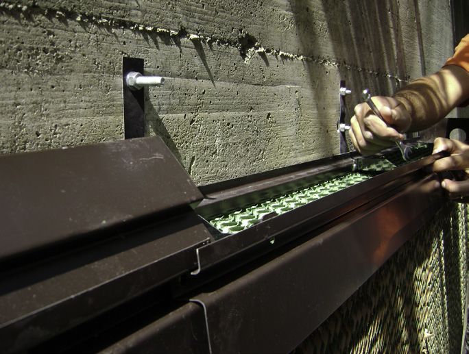
Contents

    1. General                                                    4
      1.1 Disclaimer                                              4
      1.2 Introduction                                            4
      1.3 Notes                                                   4

    2. Before using                                               5
      2.1 Delivery check                                          6
      2.2 Packaging and transport                                 6
      2.3 Typical installations                                   6

    3. Installation                                               7
      3.1 Mounting the brackets                                   7
      3.2 Assembling the bottom gutter                            9
      3.3 Mounting the sides                                     10
      3.4 Assembling the top gutter                              11
      3.5 Inserting the drains                                   12
      3.6 Inserting the CELdek® pads                             13
      3.7 Double "T" profile for Celdek® pads overlapping        14
      3.8 Water distribution components                          15
      3.9 Plumbing kit components for the distribution pipes     17

    4. Commissioning                                             19
      4.1 First time start up                                    19
      4.2 Setting the bleed-off rate                             19
      4.3 Trouble shooting                                       20

    5. Maintenance                                               21

      5.1 Mineral deposits                                       21
      5.2 Algae                                                  21
      5.3 Regular maintenance                                    21
      5.4 Replacement of a CELdek® pad                           22
    6. Technical specifications                                  23

      6.1 Pump functioning                                       23
      6.2 General                                                23
      6.3 Water tank                                             24

3                                           © Munters AB, 2018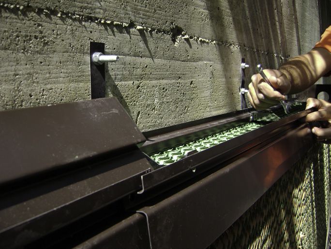
1. General

1.1 Disclaimer
Munters reserves the right to make alternations to specifications, quantities, dimensions etc. for production or
other reasons, subsequent to publication.
The information contained herein has been prepared by qualified experts within Munters.
While we believe the information is accurate and complete, we make no warranty or representation for any
particular purposes. The information is offered in good faith and with the understanding that any use of the
units or accessories in breach of the directions and warnings in this document is at the sole discretion and risk
of the user.

Any complaints concerning the products are conditioned by the strict compliance of the instructions contained
by the manual. The manufacturer reserves the right to forfeit any claims e.g. corrosion resulting from non-
observance of the instructions and non-compliant use e.g. proper bleed-off.

1.2 Introduction
Congratulations on your excellent choice of purchasing a Munters WDP gutter system!
In order to realise the full benefit from this product it is important that it is installed, commissioned and
operated correctly. Before installation or using the WDP gutter system, this manual should be studied carefully.
It is also recommended that it is kept safely for future reference.
The manual is intended as a reference for installation, commissioning and day-to-day operation of the Munters
WDP gutter system.

1.3 Notes
Date of release: April 2014.
Munters cannot guarantee to inform users about changes or to distribute new manuals to them.
All rights reserved. No part of this manual may be reproduced in any manner whatsoever without the expressed
written permission of Munters.
The contents of this manual are subject to change without notice.

                              •  All the components and spare parts MUST be stored in dry and clean
                                environment
          WARNING!            • Max environment temperature during assembling and/or storage shall not
                                exceed 50°C.
                              • DO NOT stock packages under direct sunrays.

4                                              © Munters AB, 2018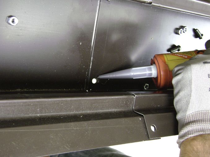
2. Before using
WARNING! The presence of Chlorine in the water will cause corrosion to the Gutter. DO NOT USE
water containing Chlorine.

WARNING! The presence of Chlorides in the water will cause corrosion to the Gutter. DO NOT
USE water having Chlorides content higher than 200mg/l.

WARNING! Do not expose the gutter system to substances containing barium polysulfide
(insecticides, pesticides and fungicides) as irreversible damage may occur to the gutter system.

Please note the limits for make-up water and sump water at ambient temperature for evaporative cooling
systems.

        Constituent                     Make-up* Water                     Sump ** Water                                           Reasons
                                                                                                           High Chlorides will cause corrosion of metal
                                                                                                           parts. Chlorides are contributed by contaminants
    Chlorides (as Cl)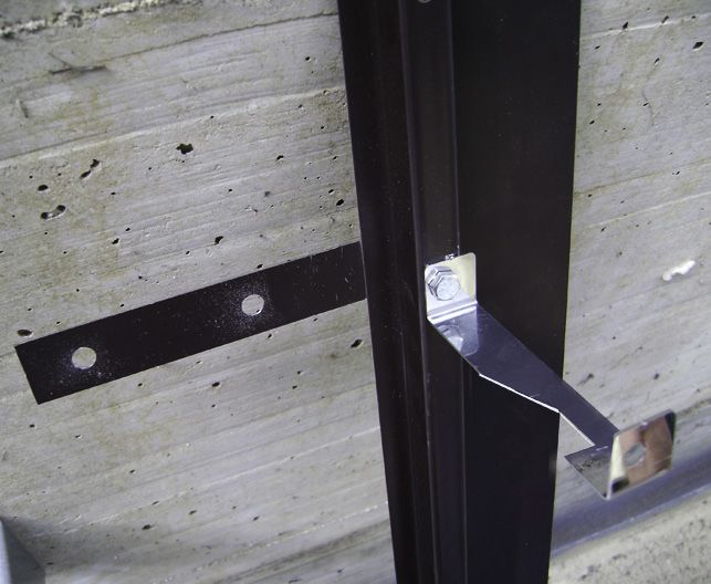
2.1 Delivery check
Upon receipt, inspect the item for external damage and if found, inform the forwarding agent without delay.
Check the data on all the rating plates of the pumps, especially voltage and frequency.
2.2 Packaging and transport
Since the gutter segments consist of numerous long pieces, care should be taken when the pieces are handled
and stored. If the pieces are placed on a heap, the sides of the heap should be supported to prevent the heap
from collapsing and causing injury.
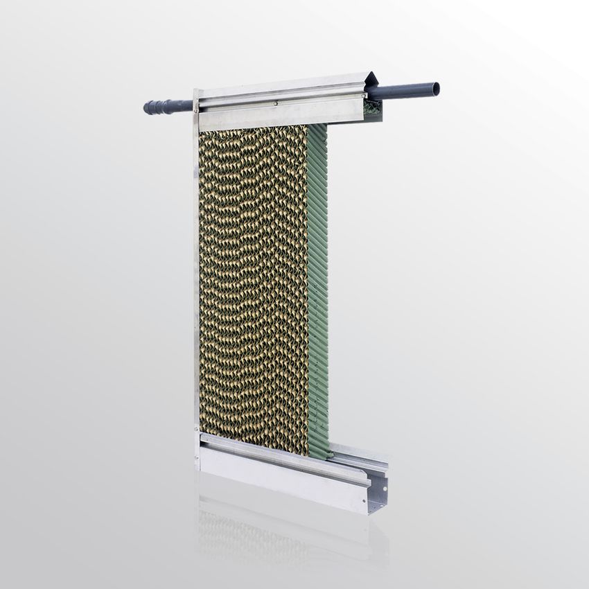
2.3 Typical installations
Typical ways in which the WDP system in combination with CELdek® evaporative cooling pads can be
installed in structures are indicated in the diagrams below. The diagrams depict structures as seen from above
with the relative placement of Euroemme® extraction fans and CELdek® evaporative cooling pads. The
WDP system is intended for installation on the outside of the structure.
CELdek® evaporative cooling pads Extraction fans
CELdek® evaporative cooling pads
WDP gutter system
Structure wall
6 © Munters AB, 2018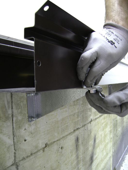
3. Installation

                       3.1 Mounting the brackets
                       The gutter sections are manufactured in five different
                       lengths, 3m, 2.4, 1.8, 1.2 and 0.6m. An installation
                       can be compiled by using different combinations
                       of the lengths. Use Diagram 1 to decide on the
                       placement of the various lengths of gutter.
                       Mount each bottom bracket using q.ty 2, Ø8 Fisher.
                       Mount each top bracket using q.ty 2,Ø6 Fisher.

                       ALIGNMENT!

                                 Ensure that all the top brackets and a the
                                 bottom brackets are mounted on the same
                                 horizontal level. Use a spirit-level or other
                                 suitable device. (see pictures on side)
                       Verify the distance between the top and bottom
                       brackets continuously. Place the bottom support
                       gutter every meter and the top gutter support where
                       it is required.
    H+212

7           © Munters AB, 2018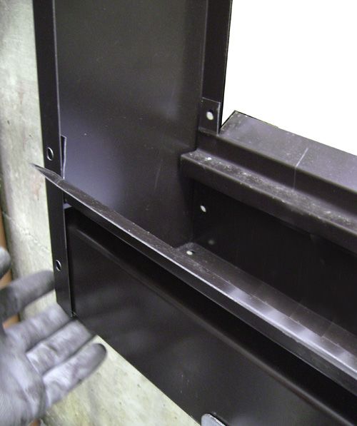
Gutter sections
Available lengths: 0.6 m – 1.2 m – 1.8 m – 2.4 m – 3.0 m

It is recommended to use as many as possible 3.0 m sections, than complete the required length with a shorter
cut on size section.
Please note that total length must be a multiple of 0.6 m.

Examples:

1.     total length 12 m:     use q.ty 4 sections with 3.0 m length;
2.     total length 16.8 m:   use q.ty 5 sections with 3.0 m length and q.ty 1 section with 1.8 m length.

Water supply and drain
Using 0.75 hp pump on 100 mm thick evaporative pad it is suggested to place a water supply every 24 m and
a water drain every 12 m.
Using 0.75 hp pump on 150 mm thick evaporative pad it is suggested to place a water supply every 16 m and
a water drain every 12 m.
If several water connections are required, divide distance between them uniformly.

q.ty 2 water connections                             L/4          L/2        L/4

q.ty 3 water connections                             L/6          L/3          L/3         L/6

q.ty 4 water connections                             L/8          L/4          L/4           L/4            L/8

                                                     Diagram 1

8                                            © Munters AB, 2018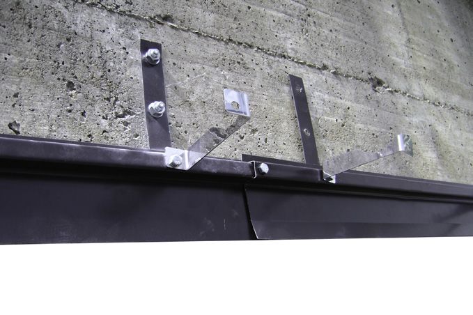
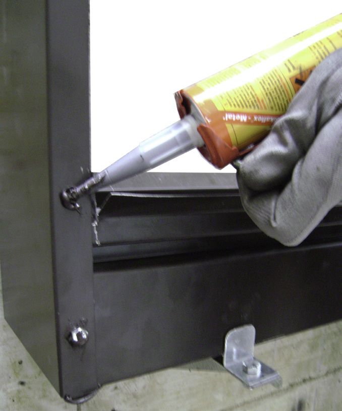
3.2 Assembling the bottom gutter
        Join the section of the bottom gutter, then start
        applying silicon in correspondence of the holes. Fix the
        bottom gutter using q.ty 6, M6 x 16 hex screws and its
        nuts.
        Apply silicon to the groove on the bottom gutter as
        indicated in the picture on the left. Do it for both sides
        of the gutter.
        To ensure a watertight seal, apply silicon to both the inside
        and outside of the gutter and spread it.
        Once the whole bottom gutter length has been
        assembled and the silicon cured, wash any debris out by
        using water. Lock it on its support as shown in the
        picture.
        In the 150mm thickness gutter add the extra
        CELdek® Pad support supplied every 600mm.
        Note: the new CELdek Pad supports are supplied unfolded
        (flat).
        Before installing the CELdek pad supports, please bend the
        flat edges on the dotted lines, forming a square cube like
        indicated below. After, please place the extra CELdek Pad
        supports inside the bottom gutter every 600mm.

9   © Munters AB, 2018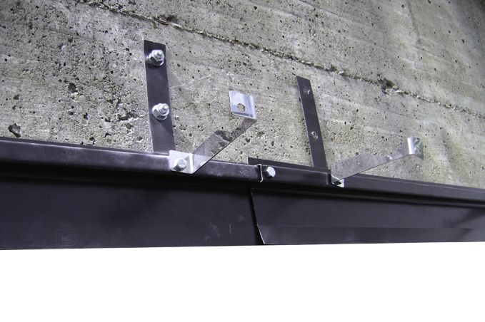
3.3 Mounting the sides

                1. In correspondence of the side panels cut the
                   bottom gutter at 30mm distance from the
                   external edge, then bend it flat.

                2. Apply the silicon on the bottom part of the sides
                   and in correspondence of the holes.

                3. Fix the side to the bottom gutter by q.ty 6, M6x16
                   hex-screws and its nuts. Tighten bolts and nuts
                   by mean of q.ty 2, Ø 10 spanner.

10   © Munters AB, 2018
3.4 Assembling the top gutter
1. Join each top gutter support sliding into the top
side gutter groove then fix them to the water
distribution pipe support by q.ty 1,M6 x 16 hex-
screw and its nut.
2. Join the complete assembly you have obtained
to the side panels (both sides) by q.ty 1, M6 x 30
screw and its nut.
3. Fix the top gutter support to the wall by using
q.ty 2, Ø6 screw anchors.
4. Continue to secure the top gutter support to the
wall joining togheter the top side panels.
11 © Munters AB, 20183.5 Inserting the drains
Use Diagram 1 to decide on the placement of the
drains.
There should be one drain every 12m in 100mm
gutter thickness and every 12m in 150mm gutter
thickness.
Once the positions of the drains have been identified,
drill holes of ø 60 mm into the bottom gutter.
Put the rubber gasket on the threaded spout, then
insert the spout in the hole of the bottom gutter and
tight it in it's position by screwing the threaded ring
placed on the other side of gutter.
12 © Munters AB, 20183.6 Inserting the CELdek® pads
Shake every pad and distributor before inserting in
order to remove dust.
Insert the CELdek® as indicated in the picture on
the left.
Ensure that all pads are moved tightly together once
inserted.
Insert the distributor pad from the top side as
indicated.
Ensure that the vertical alignment between the
CELdek® and the gutters is in line as indicated.
The last pad and distributor may need to be trimmed.
Use a saw if trimming is required.
Right Wrong
Place the top side gutter onto the distributor pad
and join it to water distribution pipe support by q.ty
1, M6 x 30crew and its nut.
Join each top side gutter as previously described. Fix
the complete assembled you have obtained to the
side panel by q.ty 1, M6 x 30 screw and its nut.
13 © Munters AB, 20183.7 Double "T" profile for CELdek ®
pads overlapping.
When you order these item you will recive the double
"T" profile in the same lenght of the gutter system
you asked for. Screw the nut into the threaded bar
and than put in with the washer into the square hole
as shown in the pict.
Then put the "T" profile on the CELdek® pad.
In order to lock the T profile place on the opposite
side the other T profile inserting the threaded bar
into the square hole, then put the Ø6 washer and
screw the M6 nut. Make this operation for all the T
profile lenght in correspondence of the square hole.
Make sure to place the double T profile inside the
side panel as shown in the picture.
Overlap the CELdek® pad and tighten all the nuts
of the threaded bar.
After that follow the top gutter assembling
instruction.
14 © Munters AB, 20183.8 Water distribution components.
All the threaded connections need to have Teflon
tape wrapped tightly around the thread to ensure a
watertight seal, while sleeved connections need to be
glued with PVC glue.
The plastic pipe is supplied in 2 sections. One is 1m
T long and the second is supplied according to the
installation demands.
The plastic tube is supplied in 1 section of 1,8m
long.
Plumbing kit components
Pos. Pict. Description Q.ty
2
Alimentation 1
brass valve 1/2"
12 11 5 19 20 16 14 13
15
13 12
Plastic floating
3 ball 1
5
17 18 20 19 5 11 12
11
10 Plastic pipe
9
6 DN40 1
10 11 12 13 14 L=1000
5
8 Male threaded
5 adaptor 3
7 40x50x1.1/4
6
5
Male threaded
9 tee adaptor 1
4 1.1/4 FFF
3
2
10 Threaded nipple 2
1
1.1/4"
Single union
11
valve F/F 2
threaded
1.1/4FF
15 © Munters AB, 2018Pos. Pict. Description Q.ty
Plastic pipe
19 DN40 2
12
Threaded hose 2 L=200
adaptor 1.1/4x4°
Male theaded
5 adaptor 2
13
Metal clamp 3 40x50x1.1/4"
40/63
Single union valve
11 F/F threaded 2
14
Spiralled pipe 1,8 1.1/4"FF
D40
PTFE tape 2
Solvent cement -
hose adaptor
17 40x40 1
Water distribution plastic pipe.
PVC cement
- 1
glue Pos. Pict. Description Q.ty
Water distribution
20 pipe 1
PTFE tape
- 2
Pump and tank.
Pos. Pict. Description Q.ty
Solvent cement
16 double socket 1
1 Water tank
Plastic pipe 1
L1000 for h1500 wdp
15 1
L1500 for h2000 wdp
L2000 for h3000 wdp
7 Water tanl lid 1
Male threaded
18
tee adaptor 1
40x40x1.1/4"
FFF
8 Trap door 1
Plunbing kit components for distribution pipes.
Pos. Pict. Description Q.ty
Threaded
12 hose adaptor 2 4 Pump 1
1.1/4"x40
16 © Munters AB, 20183.9 Plumbing kit components for distribution pipes Using exploded view to rightly select the "T" piece with threaded central for the water supply. Put the seal into the plastic pipe in correspondence of its groove. Scratch the thread before wrapping the teflon tape around it. Apply the PVC cement glue around the plastic pipe and spread it. Join all the components as shown in the picture. Make sure to place the all assembling you have obtained in the right position as shown in the picture with the water supply hole of the hose adaptor and the water distribution hole of the plastic pipe top oriented. Connect the water distribution pipe in order to cover the system length. Connect the plumbing kit hose adaptor to the water distribution pipes hose adaptor as shown in the picture by mean of q.ty 1, plastic tube and q.ty 2 metal pipe. 17 © Munters AB, 2018
Join all the components as shown in the pictures by using teflontape and the
                               PVC cememt glue.
                               Insert the complete assemble you have obtained in the side panel hole and then
                               put it into the water distribution pipe.

Make this operation for both side of the gutter.

Put the top cover gutter onto the side top gutter pushing it into the groove.

Cut the two top cover gutter in correspondence to
the water supply hose adaptor.

18                                            © Munters AB, 2018
4. Commissioning
4.1 First time start up
• After the gutter, pads and plumbing kit have been installed, connect the fresh water supply to the float
valve in the tank and the pump to the electrical supply. The electrical connections should be done by a
qualified electrician according to local laws and regulations.
• Remove any visible material from the tank and the gutter.
• Open the water supply to the tank.
• Remove the drain pipes from the tank.
• Once the tank has filled to the float valve, the pump can be started.
• Let the system run for at least 15 minutes with the drain pipes still not connected to the tank. This will
clean debris that might have been left in the system during the installation process.
• Make a note of any leaks that might have occurred.
• Switch the pump off.
• Let all the water drain from the drain pipes before they are replaced into the tank.
• Unscrew the cap of the filter and clean the filament if necessary. Replace both the filament and the cap
• If there were any leaks, dry the places where the leaks occurred and re-seal.
• If necessary, start the system again an check again for any leaks.
4.2 Setting the bleed-off rate
The bleed-off rate is the water flow that needs to be constantly drained off to keep the mineral concentration
in the water to an optimal level. Too little bleed-off means too much scaling and clogging, resulting in frequent
pad change. Too much bleed-off results in high water costs. It is therefore important to calculate the optimal
bleed-off rate to get a long lasting pad with high performance.
As a good starting value, use 0.2l/minute/running meter of gutter. If scaling becomes apparent, increase the
amount of bleed-off.
To adjust the bleed-off, follow the steps listed below:
• place a 10l bucket underneath the outlet of the bleed-off;
• start the pump and allow it to run until the return water starts flowing into the tank;
• open the bleed-off valve and start measuring the time and continue to measure the time until the bucket
is filled;
• use the table below as a quick guideline of how long it should take to fill the bucket with water. Adjust
the opening of the valve more or less according to how long it has taken to fill the bucket. Once the right
opening size for the valve is determined, keep the valve at this position to ensure constant bleed-off.
As an alternative to the table, the following formula can be used to calculate the filling time for any size
container.
19 © Munters AB, 2018Time = [Container volume] / [Length of gutter x 0.2] Gutter Total bleed- Time to fill a
The quantity of water required is not dependant on the length off required 10l bucket
height of the pads installed. [meter] [l/hour] [min]
6 75.0 8
9 112.5 5½
12 150.0 4
15 187.5 3¼
18 225.0 2¾
21 262.5 2½
24 300.0 2
4.3 Trouble shooting
Problem Possible fault Corrective action
No water circulating Pump doesn’t work Check electrical connection
Not enough water in the tank Fill the tank
Water entry joint not opened Open water entry joint
Valve closed Open valve
Water leaking from the system Plumbing components not well Close better where necessary
closed
Not enough silicon applied in Apply more silicon where necessary
junction points
20 © Munters AB, 20185. Maintenance
The performance of pads can be influenced by the formation of either mineral deposits or algae. The methods
used for the prevention of either of the two are different and are described below.
5.1 Mineral Deposits
During the evaporative cooling process some of the water evaporates, but the mineral salts remain in the
water. This effectively increases the concentration of the mineral salts in the water, which leads to an increased
likelihood for the formation of mineral deposits on the surface of the pads. The thickness of such deposits
will increase over time and ultimately block the air passages and diminish the effectiveness of the pads. Below
are some helpful guidelines for the prevention of the formation of mineral deposits.
• Ensure there is sufficient water in circulation in the system. This helps to wash dirt down from the pads.
If 100mm thick pads are used, there should be at least 3.6l/min/running meter of gutter.
• Ensure sufficient bleed-off.
• In extremely dry circumstances the water quantity may be increased.
• too much water shouldn’t be pumped up because this would transform the cooling pad wall into a closed
water curtain jeopardizing the performances.
• Minimize the number of on/off wetting cycles for the cooling pads.
• Brush dry pads with a soft bristled brush when small crystals start forming. Ensure that the brush
strokes are in the direction of the sheets in the pad (up and down). Do not use chemicals on the pad.
5.2 Algae
Algae require three essential elements to survive:
• Light
• Water
• Nutrients
Anywhere that an abundance of the three are required, the likelihood of algae growth is high. Below are some
recommendations that will help to reduce the likelihood of algae growth
• Completely dry the cooling pads once every 24 hours.
• It is not recommended to use chemicals on a daily basis.
• Shade the pads and the tank.
• Flush and disinfect the entire system quarterly.
5.3 Regular maintenance
• Clean the filter of the plumbing kit and pump regularly, dirty filter can reduce the water flow rate by
50% or more.
• Check system regularly for damaged or clogged cooling pads and replace damaged pads.
21 © Munters AB, 20185.4 Replacement of a CELdek® pad
Change pads only when the system is completely
dried.
Cut out the pad that needs to be replaced and
remove it.
Cut the new pad in the middle to obtain two pieces.
Insert the new distributor (it’ll remain inside the top
gutter).
Insert the upper part of the CELdek® that has been
cut. Ensure that the pad is at an angle.
Insert the second half at an angle as indicated on
the left.
Push two pieces in together until they are flush with
the other pads.
22 © Munters AB, 20186. Technical specifications
6.1 Pump functioning
The float switch on the pump is there for protection
of the pump, should the water level become too low.
The diagram below illustrates how the float switch
operates. Please take note at which levels the pump will
switch off and at which level it will switch on again.
6.2 Pump functioning
Pump Nominal power Type phases Frequency Voltage Current Max capacity Weight
type [W] [hp] [Hz] [V] [A] [l/min] [m] [kg]
a 0.25 0.33 1 50 230 1.4 128 1.7 3.75
b 0.25 0.33 1 60 230 1.4 128 1.7 3.75
c 0.37 0.5 1 50 230 2.1 165 2.9 4.7
d 0.37 0.5 1 60 230 2.1 165 2.9 4.7
e 0.55 0.75 1 50 230 3.5 250 3.8 6
f 0.55 0.75 1 60 230 3.5 250 3.8 6
g 0.55 0.75 3 50 400 1.9 250 3.8 6
h 0.55 0.75 3 60 400 1.9 250 3.8 6
Max operating temperature 40°C
Discharge pipe connection 11/4''
Pump shaft Acciaio inossidabile AISI 416
Pump body Type a-d: polipropilene / Type e-h: acciaio inossidabile AISI 304
IEC protective class IP68
Winding insulation grade Type a-d: F / Type e-h: B
Kit h 1.5= 2.7m
Kit h 2.0= 3.2m
Kit h 3.0= 3.7m
23 © Munters AB, 20186.3 Water Tank
Tank Capacity W D H
type
[l] [mm] [mm] [mm]
A 300 800 660 860
B 500 990 840 910
Kit A= 400mm
Kit B= 500mm
24 © Munters AB, 2018Munters Italy S.p.a, al fine di migliorare la qualità di prodotti e servizi, si riserva il diritto di modificare in
qualsiasi momento e senza alcun preavviso le specifiche e le istruzioni d’uso contenute in questo manuale.
Le informazioni contenute nel presente manuale sono state preparate da personale qualificato Munters.
Nonostante si ritenga che le informazioni fornite siano accurate e complete, non si garantisce il funzionamento
del prodotto in condizioni diverse da quelle indicate nel presente manuale. Le informazioni sono fornite in
buona fede e con la consapevolezza che ogni uso delle unità o degli accessori in violazione delle direttive
o avvertenze contenute in questo documento è ad esclusiva discrezione e rischio dell’utilizzatore.
25 2014
© Munters AB, 2018Contenuti
1. DISPOSIZIONI GENERALI 4
1.1 Avvertenze 4
1.2 Introduzione 4
1.3 Note 4
2. PRIMA DELL’USO 5
2.1 Controlli alla consegna 6
2.2 Imballaggio e trasporto 6
2.3 Installazione tipica 6
3. INSTALLAZIONE 7
3.1 Montaggio delle staffe 7
3.2 Assemblaggio della canalina inferiore 9
3.3 Montaggio dei laterali 10
3.4 Assemblaggio della canalina superiore 11
3.5 Inserimento degli scarichi 12
3.6 Inserimento dei pannelli evaporativi CELdek® 13
3.7 Montaggio profili a “doppio T” 14
3.8 Componenti del sistema di distribuzione dell’acqua 15
3.9 Componenti del kit idraulico per tubi di distribuzione 17
4. COLLAUDO 19
4.1 Messa in funzione (primo utilizzo) 19
4.2 Regolazione della portata di bleed-off 19
4.3 Risoluzione dei problemi 20
5. MANUTENZIONE 21
5.1 Depositi mineralis 21
5.2 Alghe 21
5.3 Manutenzione programmata 21
5.4 Sostituzione dei panelli evaporativi CELdek® 22
6. SPECIFICHE TECNICHE 23
6.1 Funzionamento della pompa dell'acqua 23
6.2 Specifiche tecniche della pompa ad immersione 23
6.3 Serbatoio d’acqua 24
26 © Munters AB, 20181. Disposizioni generali
1.1 Avvertenze
Munters Italy S.p.a, al fine di migliorare la qualità di prodotti e servizi, si riserva il diritto di modificare in
qualsiasi momento e senza alcun preavviso le specifiche e le istruzioni d’uso contenute in questo manuale.
Le informazioni contenute nel presente manuale sono state preparate da personale qualificato Munters.
Nonostante si ritenga che le informazioni fornite siano accurate e complete, non si garantisce il funzionamento
del prodotto in condizioni diverse da quelle indicate nel presente manuale. Le informazioni sono fornite in
buona fede e con la consapevolezza che ogni uso delle unità o degli accessori in violazione delle direttive o
avvertenze contenute in questo documento è ad esclusiva discrezione e rischio dell’utilizzatore.
Qualsiasi reclamo relativo al prodotto è condizionato dalla rigorosa osservanza delle istruzioni contenute nel
presente manuale. Il produttore si riserva il diritto di respingere qualsiasi rivendicazione (esempio: corrosione)
derivante dalla mancata osservanza delle istruzioni e da un uso non conforme del prodotto (esempio: bleed-
off non adeguato).
1.2 Introduzione
Congratulazioni per la vostra eccellente scelta di aver acquistato un prodotto Munters.
Al fine di ottenere i migliori risultati da questo prodotto è importante che sia installato, collaudato e operi
correttamente. Prima di installare o usare la canalina, questo manuale deve essere studiato attentamente. Si
raccomanda inoltre di conservarlo perché possa essere consultato successivamente in caso di necessità.
Questo manuale è stato pensato come riferimento per l’installazione, il collaudo e le operazioni quotidiane di
utilizzo della canalina.
1.3 Note
Data di rilascio: aprile 2014.
I contenuti di questo manuale possono essere soggetti a cambiamenti senza preavviso.
Munters non può assicurare di informare gli utilizzatori sui cambiamenti introdotti o di distribuire manuali
aggiornati.
Tutti i diritti sono riservati. Nessuna parte del manuale può essere riprodotta in alcun modo senza il permesso
scritto della Munters.
I contenuti di questo manuale possono essere soggetti a cambiamenti senza preavviso.
• Tutti i componenti e i ricambi DEVONO essere stoccati in
un ambiente secco e pulito.
WARNING! • La temperatura ambiente massima durante l'assemblaggio e/o lo
stoccaggio non deve superare i 50°C.
• NON stoccare gli imballaggi sotto raggi diretti del sole.
27 © Munters AB, 20182. Prima dell’uso
AVVERTENZA! La presenza di cloro nell’acqua causerà la corrosione della canalina. NON USARE
acqua contenente cloro.
AVVERTENZA! La presenza di cloruri nell'acqua causerà la corrosione della canalina. NON USARE
acqua con contenuto di cloruri superiori a 200 mg/l.
AVVERTENZA! NON ESPORRE la canalina o i pannelli evaporativi a sostanze contenenti polisolfuro
di bario (insetticidi, pesticidi e fungicidi) perché possono causare danni irreversibili alla canalina ed
ai pannelli evaporativi stessi.
Si prega di prendere nota delle indicazioni contenute nella seguente tabella, relativi a entrambe le tipologie di
acqua utilizzate nel sistema, ossia l'acqua di reintegro (Make-up Water*), e l’acqua per il ricircolo presente nel
serbatoio a temperatura ambiente (Sump Water*).
L'acqua di
Costituenti Sump ** Water Ragioni
reintegro
La presenza elevata di cloruri causa la corrosione
delle parti metalliche. I cloruri sono sali contenenti
Cloruri (come Cl)2.1 Controlli alla consegna
Con la ricevuta d’acquisto, ispezionare i componenti della canalina per verificare la presenza di danni esterni
e, se eventualmente riscontrati, informare l’agente spedizioniere al più presto possibile. Controllare i dati sulle
targhette delle pompe, specialmente quelli relativi a voltaggio e frequenza.
2.2 Imballaggio e trasporto
Dato che la canalina è costituita da numerosi parti di una certa lunghezza, si raccomanda di prestare la massima
attenzione nel maneggiare e immagazzinare i componenti. Se il materiale viene accatastato, i lati della catasta
devono essere supportati al fine di prevenirne il collasso e dunque infortuni.
2.3 Installazione tipica
Nel diagramma sottostante sono indicate le modalità più comuni in cui può essere installato il sistema WDP,
in combinazione con i pannelli evaporativi CELdek. I diagrammi rappresentano le strutture con vista dall’alto
con il relativo posizionamento dei ventilatori-estrattori e dei pannelli evaporativi CELdek. Il sistema WDP è
pensato per l’installazione all’esterno delle strutture.
Pannelli evaporativi CELdek® Ventilatori estrattori
pannelli evaporativi CELdek®
WDP Sistema di distribuzione dell’acqua
Parete
29 © Munters AB, 20183. Installazione
3.1 Montaggio delle staffe
Le sezioni della canalina sono prodotte in cinque
differenti lunghezze: 3m, 2.4m, 1.8m, 1.2 m e 0.6m.
L’installazione può essere effettuata usando differenti
combinazioni di lunghezze.
Montare ogni staffa inferiore usando 2 viti diametro
8mm tipo Fisher.
Montare ogni staffa superiore usando 2 viti diametro
6mm tipo Fisher.
ALLINEAMENTO!
Assicurarsi che tutte le staffe superiori ed
inferiori siano montate allo stesso livello
orizzontale. Usare una bolla od un altro
strumento analogo.
Verificare che la distanza tra le staffe superiori ed
inferiori rimanga costante su tutta la lunghezza.
MURO
Posizionate le staffe inferiori per ogni metro di
lunghezza e le staffe superiori dove necessario.
H+212
MURO
30 © Munters AB, 2018Sezioni della canalina
Lunghezze disponibili: 3.0m, 2.4m, 1.8m, 1.2m e 0.6m.
Si consiglia di usare quante più sezioni possibili con lunghezza 3m, e poi completare la parete con la sezione
corta di dimensione più appropriata.
Si noti attentamente che tutte le sezioni sono multipli di 0.6m.
Esempi:
1. Lunghezza totale 12m: usare 4 sezioni da 3m di lunghezza.
2. Lunghezza totale 16.8m: usare 5 sezioni da 3m di lunghezza e 1 sezione di 1.8m di lunghezza.
Alimentazione dell’acqua e scarichi
Usando una pompa da 0.75 hp con panelli evaporativi di spessore 100mm, si suggerisce di posizionare
un’alimentazione ogni 24m e uno scarico ogni 12m.
Usando una pompa 0.75 hp per panelli evaporativi di spessore 150mm, si suggerisce di posizionare
un’alimentazione ogni 16m e uno scarico per ogni 12m.
Se sono necessari più punti di alimentazione dell’acqua, dividere la distanza tra di essi in modo uniforme.
.
q.tà 2 connessioni di acqua L/4 L/2 L/4
q.tà 3 connessioni di acqua L/6 L/3 L/3 L/6
q.tà 4 connessioni di acqua L/8 L/4 L/4 L/4 L/8
Diagramma 1
31 © Munters AB, 20183.2 Assemblaggio della canalina inferiore
Unire le sezioni della canalina inferiore, poi applicare del
silicone in corrispondenza dei fori. Fissare la canalina inferiore
usando 6 viti M6x16 e relativi dadi.
Applicare del silicone nella fessura del giunto centrale
inferiore come indicato nel diagramma a sinistra. Ripetere
l’operazione per entrambi i lati del giunto.
Per assicurare la tenuta all’acqua, applicare il silicone sia
internamente che esternamente ai giunti e stenderlo fino a
formare uno strato protettivo.
Terminato l’assemblaggio dell’intera lunghezza della canalina
inferiore, attendere che il silicone si asciughi, quindi pulire da
eventuali detriti usando acqua. Posizionare la canalina sui suoi
supporti e fissarla come indicato nella foto.
Per panelli evaporativi di spessore 150mm posizionare i
supporti supplementari ogni 0.6m.
Nota: i nuovi supporti supplementari sono forniti spianati
(piatti).
Prima di installare i supporti supplementari, piegare i bordi
piatti sulle linee tratteggiate, formando un cavallotto come
indicato di seguito. Si prega quindi di inserire i supporti
supplementari all'interno della grondaia inferiore ogni 600mm.
32 © Munters AB, 20143.3 Montaggio dei laterali
1. In corrispondenza dei pannelli laterali tagliare la
canalina inferiore a 30mm di distanza dal bordo
esterno, poi piegare come rappresentato nel
disegno.
TAGLIARE E 2. Applicare del silicone nella parte inferiore dei
PIEGARE laterali ed in corrispondenza dei fori.
3. Fissare il laterale al profillo inferiore usando 6
viti M6x16 e relativi dadi.
Stringere le viti e dadi usando 2 chiavi di misura
10.
33 © Munters AB, 20183.4 Assemblaggio della canalina superiore
1. Montare ogni supporto del profilo superiore
alloggiandolo nella scanalatura e fissarlo insieme
al supporto del tubo di distribuzione dell’acqua
usando una vite M6x16 e relativo dado.
2. Assemblare a tutti i componenti ottenuti i
pannelli laterali (da entrambi i lati) usando una
vite M6x30 e relativo dado.
3. Fissare il supporto della canalina superiore al
muro usando 2 viti di ancoraggio diametro 6mm.
4. Continuare a fissare il supporto della canalina
superiora alla parete, unendo tra loro i pannelli
laterali superiori.
34 © Munters AB, 20183.5 Inserimento degli scarichi
Utilizzare il diagramma 1 per stabilire la disposizione
degli scarichi.
E’ previsto uno scarico per ogni 12 m di lunghezza
di canalina.
Una volta identificata la posizione degli scarichi,
praticare dei fori di ø 60 mm nella canalina inferiore.
Per assicurare una tenuta stagna, applicare del
silicone sia internamente che esternamente ai giunti
e stenderlo fino a formare uno strato protettivo.
Inserire la guarnizione di gomma sulla parte filettata
del bocchettone di scarico, poi inserire il bocchettone
nel foro praticato nella canalina inferiore e fissarlo
usando la ghiera filettata in plastica.
35 © Munters AB, 20183.6 Inserimento dei pannelli evaporativi
CELdek®
Prima di installare i pannelli ed i pannelli distributori,
assicurarsi che siano ben puliti e privi di polvere e
sporcizia.
Inserire i pannelli CELdek come indicato nel
diagramma a sinistra.
Flusso
d'aria Assicurarsi che tutti i pannelli, una volta inseriti,
siano ben affiancati l’uno all’altro.
Inserire il pannello distributore dal lato superiore,
come indicato.
Assicurarsi che l’allineamento verticale tra i pannelli
CELdek e le canaline sia corretto, come da schema
a lato.
L’ultimo pannello e l’ultimo distributore poterebbero
necessitare di una rifilatura. In tal caso usare un
seghetto od uno strumento analogo.
Giusto Sbagliato
Posizionare la parte laterale superiore della canalina
sul pannello distributore ed unire al supporto del
tubo di distribuzione dell’acqua usando una vite
M6x30 e relativo dado.
Unire ogni parte laterale superiore della canalina come
descritto sopra. Fissare l’insieme dei componenti
ottenuti insieme al pannello laterale usando una vite
M6x30 e relativo dado.
36 © Munters AB, 20183.7 Montaggio profili a “doppio T”
In caso vengano ordinati, i profili “doppio T”
saranno forniti della stessa lunghezza della canalina.
Avvitare il dado alla barra filettata ed inserire il tutto
nei fori quadrati, insieme alla rondella (vedere foto).
Poi posizionare il profillo “T” sui i pannelli CELdek.
Per bloccare i profili a “T”, posizionare un secondo
profilo a “T” sul lato opposto, inserire la barra
filettata nel corrispondente foro quadrato ed infine
posizionare la rondella diametro 6mm ed il dado
M6. Ripetere l’operazione per tutti i profilli a “T” in
corrispondenza dei fori quadrati.
Assicurare che i profili a “T” siano inserititi nei
pannelli laterali come indicato nella foto.
Sovrapporre i pannelli CELdek e avvitare tutti i dadi
delle barre filettate.
Proseguire con l’assemblaggio della parte superiore
della canalina.
37 © Munters AB, 20183.8 Componenti del sistema di
distribuzione dell’acqua
Tutti i giunti filettati necessitano di nastro Teflon
correttamente avvolto attorno alla filettatura per
assicurarne la tenuta all’acqua. I giunti ad incollaggio
necessitano invece di essere assemblati con del
collante specifico per PVC.
I tubi di plastica sono forniti in sezioni di due diverse
lunghezze, una da 1 m e l’altra in base alle esigenze
di installazione. I tubi spiralati sono forniti in sezioni
lunghi 1.8m.
Componenti:
Pos. Figura Descrizione Q.tà
Valvola
2 d’alimentazione 1
1/2"
12 11 5 19 20 16 14 13
Sfera
15 3 galleggiante di 1
13 12 plastica
5
17 18 20 19 5 11 12
11
Tubo di plastica
10 6 DN40 1
9
L=1000
10 11 12 13 14
5
Adattatore
8 5 filettato M 3
40x50x1.1/4
7
6 Raccordo a “T”
5
M filettato
9 tipo “T” 1
4 1.1/4 FFF
3
2
10 Nipplo filettato 2
1
1.1/4"
Valvola sfera
11 filettata F/F 2
1.1/4FF
38 © Munters AB, 2018Pos. Pict. Description Q.ty
Tubo plastica
Portagomma 19 DN40 2
12 filettato 2 L=200
1.1/4x4°
Adattatore
Fascetta 5 filettato 2
13 metallica 40/63 3 40x50x1.1/4"
Valvola sfera
11 filettata F/F 2
14
Tubo spiralato 1,8 1.1/4"FF
D40
Nastro PTFE 2
Portagomma a
-
incollaggio
17 1
40x40
Tubo di plastica di distribuzione dell'acqua.
Colla vinilica
- 1
per PVC Pos. Pict. Description Q.ty
Tubo
20 distribuzione 1
Nastro PTFE dell’acqua
- 2
Pompa e serbatoio per acqua
Pos. Pict. Description Q.ty
Manicotto
16 incollaggio 1
1
Serbatoio per
acqua 1
Tubo plastica
L1000 per h1500 wdp
15 1
L1500 per h2000 wdp
L2000 per h3000 wdp
Coperchio
7 serbatoio 1
Raccordo a “T”
18
M filettato 1
40x40x1.1/4"
FFF
Coperchio
8 serbatoio 1
Componenti del kit idraulico per tubi di distribuzione.
Pos. Pict. Description Q.ty
Portagomma
12 filettato 2 4 Pompa 1
1.1/4"x40
39 © Munters AB, 20183.9 Componenti del kit idraulico per tubi di distribuzione Usare il disegno esploso per selezionare correttamente il raccordo a “T” filettato per il tubo dell’acqua. Applicare il sigillante sul tubo di plastica in corrispondenza del foro. Raschiare il filetto prima di avvolgere il nastro di Teflon intorno ad esso. Applicate la colla vinilica per PVC intorno al tubo di plastica e stenderla uniformemente. Unire tutti i componenti come indicato nella foto. Assicurarsi di montare tutto l’assemblato così ottenuto nella giusta posizione, come mostrato nella foto. Il foro di alimentazione dell'acqua del portagomma e i fori di distribuzione dell'acqua del tubo di plastica devono essere rivolti verso l’alto. Collegare via via i tubi di distribuzione dell’acqua fino a coprire l’intera lunghezza del sistema. Collegare il portagomma del kit idraulico al portagomma del tubo di distribuzione dell’acqua utilizzando il tubo spiralato e le due fascette metalliche (vedere foto). 40 © Munters AB, 2018
Unire tutti i componenti come illustrato nelle foto, usando il nastro di Teflon e
                               la colla vinilica per PVC.
                               Inserire l’assemblato così ottenuto nel foro praticato nel pannello laterale e poi
                               collegare al tubo di distribuzione dell’acqua.

Effettuare questa operazione per entrambi i lati della canalina.

Inserire il coperchio nella parte superiore della canalina spingendolo nella
scanalatura.

Tagliare i due coperchi della canalina in
corrispondenza del portagomma di alimentazione
dell’acqua.

41                                             © Munters AB, 2018
4. Collaudo
4.1 Messa in funzione (primo utilizzo)
• Dopo che canalina, pannelli e kit idraulico sono stati installati, connettere l’alimentazione dell’acqua al
galleggiante nel serbatoio e la pompa all’alimentazione elettrica. La connessione elettrica dovrebbe essere
effettuata da un elettricista qualificato in funzione della normativa locale.
• Rimuovere tutto il materiale (sporcizia od altro) eventualmente presente nel serbatoio e nella canalina.
• Una volta che il serbatoio si sarà riempito fino al galleggiante, la pompa potrà essere azionata.
• Far funzionare il sistema per almeno 15 minuti con i tubi di scarico non ancora connessi al serbatoio.
Quest’operazione permette la rimozione del materiale che potrebbe esser rimasto nel sistema durante le
operazioni di montaggio.
• Prendere nota di qualsiasi perdita che si fosse eventualmente verificata.
• Spegnere la pompa.
• Far fuoriuscire tutta l’acqua dai tubi di scarico prima di rimetterli nel serbatoio.
• Svitare il tappo del filtro e pulire il filtro se necessario. Riposizionare filtro e tappo.
• Se ci fossero state delle perdite, asciugare e applicare nuovamente il silicone.
• Se necessario, far ripartire il sistema e controllare nuovamente eventuali perdite.
4.2 Regolazione della portata di bleed-off
La portata di bleed-off è il flusso di acqua che deve essere costantemente scaricato per mantenere la
concentrazione di minerali nell’acqua ad un livello ottimale. Un bleed-off insufficiente comporta un eccessivo
deposito di calcare, con la conseguente necessità di un frequente cambio di pannelli. Un bleed-off eccessivo
invece determina alti costi per la fornitura di acqua. E’ quindi importante calcolare una portata di bleed off
che consenta una lunga durata dei pannelli ed un’alta efficienza di esercizio.
Come valore di partenza ottimale si consiglia una portata di 0.2 l/minuto ogni metro lineare di canalina. Se il
deposito di calcare diviene evidente, aumentare la portata di bleed-off.
Per regolare il bleed-off, seguire i passaggi elencati qui sotto:
• posizionare un secchio da 10 l sotto l’uscita del bleed-off;
• accendere la pompa e farla funzionare finché l’acqua di ricircolo comincia ad affluire nel serbatoio;
• aprire la valvola del bleed-off e cominciare a misurare il tempo necessario affinché il secchio si riempia;
• usare la tabella sottostante come riferimento per determinare quanto tempo si dovrebbe impiegare per
riempire il secchio. Aumentare o ridurre l’apertura della valvola in base a quanto tempo è stato necessario
per riempire il secchio. Una volta che è stata determinata la corretta apertura della valvola, mantenerla in
posizione per assicurare un bleed-off costante.
In alternativa alla tabella, può essere usata la seguente formula per calcolare il tempo di riempimento per
qualsiasi dimensione del contenitore.
42 © Munters AB, 2018Tempo = [Volume contenitore] / [Lunghezza della Lunghezza Bleed-off Tempo per
canalina x 0.2] della totale riempire un
La quantità di acqua richiesta non è dipendente dall’altezza canalina richiesto secchio da 10l
dei pannelli installati. [metro] [l/ora] [min]
6 75.0 8
9 112.5 5½
12 150.0 4
15 187.5 3¼
18 225.0 2¾
21 262.5 2½
24 300.0 2
4.3 Risoluzione dei problemi
Problema Possibili cause Azioni correttive
l’acqua non circola La pompa non funziona Controllare le connessioni elettriche
Non c’è abbastanza acqua nel Riempire il serbatoio
serbatoio
Giunture di alimentazione aprire i giunti di alimentazione
dell’acqua non aperte dell’acqua
Valvola chiusa aprire la valvola
perdite d’acqua dal sistema Componenti idraulici non ben assemblare correttamente dove
assemblati necessario
nei punti di giunzione non è stato applicare più silicone dove necessario
applicato abbastanza silicone
43 © Munters AB, 20185. Manutenzione
Le prestazioni dei pannelli possono essere influenzate tanto dalla formazione di depositi minerali quanto di
alghe. I metodi usati per la prevenzione di entrambi sono differenti e sono descritti qui di seguito.
5.1 Depositi minerali
Durante i processi di raffreddamento evaporativo l’acqua evapora, ma non i sali minerali. Questo incrementa
sensibilmente la concentrazione di sali minerali nell’acqua, con conseguente aumento della probabilità di
formazione di depositi sulla superficie dei pannelli. Lo spessore di questi depositi aumenterà nel tempo fino
a bloccare il passaggio di aria diminuendo l’efficacia dei pannelli. Qui di seguito si riportano alcune utili linee
guida per la prevenzione della formazione di depositi minerali.
• Assicurarsi che ci sia sufficiente acqua in circolazione nel sistema. Ciò aiuta infatti ad eliminare lo sporco
dai pannelli. Se si utilizzano pannelli di 100 mm di spessore, si dovrebbero assicurare almeno 3.6 l/min per
ogni metro lineare di canalina.
• Garantire un bleed-off sufficiente.
• In condizioni ambientali di estrema siccità potrebbe essere necessario aumentare la quantità d’acqua
richiesta.
• Non dovrebbe essere pompata un’eccessiva quantità d’acqua perché ciò originerebbe sui pannelli un
involucro d’acqua compromettendo così le performances.
• Minimizzare il numero di cicli on/off di umidificazione dei pannelli.
• Nel caso in cui sui pannelli si comincino a formare dei piccoli cristalli, spazzolare i pannelli asciutti con una
spazzola morbida. Assicurarsi di spazzolare in direzione dei fogli che compongono il pannello (su e giù).
Non usare prodotti chimici sul pannello.
5.2 Alghe
Le alghe necessitano di tre elementi essenziali per sopravvivere
• Luce
• Acqua
• Nutrimento
Laddove sia presente abbondanza dei tre fattori sopra elencati, la probabilità di crescita delle alghe è alta. Qui
di seguito si riportano alcune raccomandazioni utili a ridurre la probabilità di crescita delle alghe.
• Asciugare completamente i pannelli evaporativi una volta ogni 24 ore.
• Non è consigliabile l’utilizzo quotidiano di prodotti chimici.
• Posizionare all’ombra il serbatoio ed i pannelli.
• Svuotare e disinfettare l’intero sistema ogni 3 mesi.
5.3 Manutenzione programmata
• Pulire il filtro del kit idraulico e della pompa regolarmente; un filtro sporco può ridurre la portata del 50%
o più.
• Controllare regolarmente il sistema per verificare la presenza di pannelli danneggiati o occlusi e sostituirli.
44 © Munters AB, 20185.4 Sostituzione dei panelli evaporativi CELdek®
• Sostituire un pannello solamente quando il
sistema è completamente asciutto.
• Tagliare e rimuovere il pannello da sostituire.
• Tagliare a metà il nuovo pannello per ottenerne
due pezzi.
• Inserire il nuovo distributore (rimarrà nella
canalina superiore).
• Inserire la parte superiore del CELdek® che
è stato tagliato. Assicurarsi che il pannello sia
allineato.
• Inserire la seconda metà con un inclinazione
come quella indicata a sinistra.
• Spingere i due pezzi fino ad allinearli con gli altri
pannelli.
45 © Munters AB, 20186. Specifiche tecniche
6.1 Funzionamento della pompa dell'acqua
E’ presente un interruttore di accensione collegato al
galleggiante per proteggere la pompa nel caso in cui
il livello dell’acqua dovesse ridursi eccessivamente.
Il diagramma seguente mostra come funziona
l’interruttore collegato al galleggiante. Prendete nota
del livello dell’acqua a cui la pompa si spegne e si
accende nuovamente.
6.2 Specifiche tecniche della pompa ad immersione
Kit Potenza Tipo di fase Frequenza Voltaggio Corrente Max capacità Peso
nominale
[W] [hp] [Hz] [V] [A] [l/min] [m] [kg]
a 0.25 0.33 1 50 230 1.4 128 1.7 3.75
b 0.25 0.33 1 60 230 1.4 128 1.7 3.75
c 0.37 0.5 1 50 230 2.1 165 2.9 4.7
d 0.37 0.5 1 60 230 2.1 165 2.9 4.7
e 0.55 0.75 1 50 230 3.5 250 3.8 6
f 0.55 0.75 1 60 230 3.5 250 3.8 6
g 0.55 0.75 3 50 400 1.9 250 3.8 6
h 0.55 0.75 3 60 400 1.9 250 3.8 6
Max temperatura di esercizio 40°C
Connessione tubo di scarico 11/4''
Albero pompa Acciaio inossidabile AISI 416
Corpo pompa Tipo a-d: polipropilene / Tipo e-h: acciaio inossidabile AISI 304
Classe di protezione IEC IP68
Classe di isolamento termico Tipo a-d: F / Tipo e-h: B
Kit h 1.5= 2.7m
Kit h 2.0= 3.2m
Kit h 3.0= 3.7m
46 © Munters AB, 20186.3 Serbatoio d’acqua
Kit Capacità W D H
[l] [mm] [mm] [mm]
A 300 800 660 860
B 500 990 840 910
Kit A= 400mm
Kit B= 500mm
47 © Munters AB, 2018WDP gutter system is developed and produced by Munters Italy S.p.A., Italy
www.munters.com
Ag/MIT/UmGb-2216-10/14 rev 1.0
Australia Munters Pty Limited, Phone +61 2 8843 1594, Brazil Munters Brasil Industria e Comercio Ltda, Phone +55 41 3317 5050, Canada Munters Corporation
Mason, Phone +1 517 676 7070, China Munters Air Treatment Equipment (Beijing) Co. Ltd, Phone +86 10 80 418 000, Denmark Munters A/S, Phone
+45 9862 3311, India Munters India, Phone +91 20 3052 2520, Indonesia Munters, Phone +62 818 739 235, Italy Munters Italy S.p.A., Chiusavecchia,
Phone +39 0183 52 11, Japan Munters K.K., Phone +81 3 5970 0021, Korea Munters Korea Co. Ltd., Phone +82 2 761 8701, Mexico Munters Mexico, Phone
+52 818 262 54 00, Russia Munters AB, Phone +7 812 448 5740, Singapore Munters Pte Ltd., Phone +65 744 6828, South Africa and Sub-Sahara Countries
Munters (Pty) Ltd., Phone +27 11 997 2000, Spain Munters Spain S.A., Phone +34 91 640 09 02, Sweden Munters AB, Phone +46 8 626 63 00, Thailand
Munters Co. Ltd., Phone +66 2 642 2670, Turkey Munters Form Endüstri Sistemleri A.Ş, Phone +90 262 751 3750, USA Munters Corporation Mason, Phone
+1 517 676 7070, Vietnam Munters Vietnam, Phone +84 8 3825 6838, Export & Other countries Munters Italy S.p.A., Chiusavecchia Phone +39 0183 52 11
© Munters AB, 2018You can also read