April 2021 MOLLER Forum Spectrometer Update - Juliette Mammei - The ...
←
→
Page content transcription
If your browser does not render page correctly, please read the page content below
April 2021 MOLLER Forum
 Spectrometer Update
 Juliette Mammei
Team Acknowledgements
▪ JLAB Magnet Group ▪MIT Bates REC
 ▪ Ruben Fair (CAM) ▪ James Kelsey
 ▪ Dave Kashy (Principal Mechanical Engineer – Spectrometer Lead) ▪ Ernie Ihloff
 ▪ Probir Ghoshal (Senior Electrical Engineer) ▪ Jason Bessuille
 ▪ Eric Sun (Senior Mechanical Engineer)
 ▪ Sandesh Gopinath (Mechanical Engineer)
 ▪ Randy Wilson (Mechanical Designer)
 ▪ Dan Young (Mechanical Designer)
▪ Physics Collaboration
 ▪ Juliette Mammei (Experimental Contact)
 ▪ Krishna Kumar
 ▪ Chandan Ghosh
 ▪ Sakib Rahman
 ▪ Nazanin Roshanshah
 ▪ Ciprian Gal
 ▪ Kent Paschke
 ▪ and others…
 April 21, 2021 MOLLER Forum 2
Topics
 • Choice of drift medium Exercising our “Change
 Control” muscles!
 • Segmented vs. “hybrid”
 • Results from Preliminary Design Review
 • Verification of tolerances with “worst-case” offsets
 • Engineering driven optimizations
 • Coil conductor configurations are now fixed

 April 21, 2021 MOLLER Forum 3
Spectrometer system tools In addition to TOSCA, CAD and GEANT4

 Full azimuthal acceptance
 for mollers from
 6 < < 20 mrads
 Line-drawings for apertures

particle envelopes
algorithm

 2-bounce code
 Phase space calcs

 April 21, 2021 MOLLER Forum 4
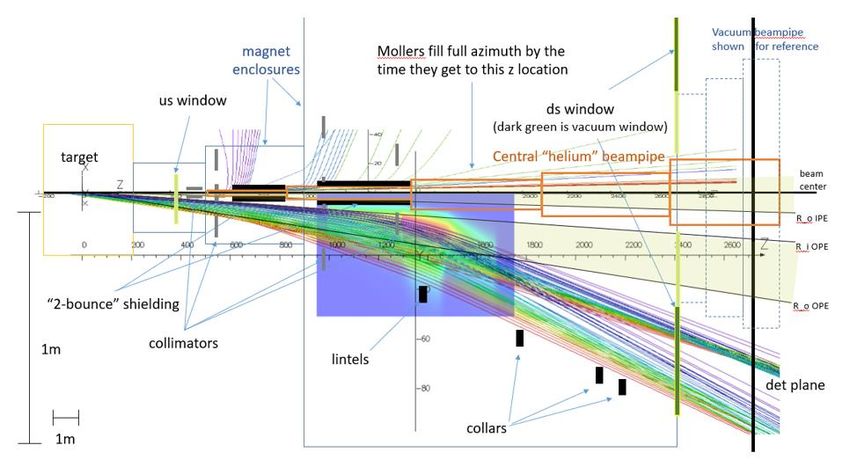
Evolution of the downstream torus
 Careful planning helped to simplify
 Proposal model
 the engineering design of the DS
 torus, though there have been
 hybrid coil prototype some changes

 Fit within radial, angular acceptances
 (360°/7 and
Choice of drift medium – vacuum
 Figures from the CCB document
 submitted for approval to use a
 vacuum vessel for the magnet
 enclosures

 Presence of the central He pipe causes
 unacceptable backgrounds

 Physics optics ok w/ ~atm of air or He

 Still need to test beamline backgrounds
 April 21, 2021 MOLLER Forum 6
Segmented vs. Hybrid Compare conductor
 configurations
 Hybrid vs. segmented – segmented wins! segmented
 blockyHybrid
 distributions at detector plane

 V1U.2a_V1DSg.3 V1U.2a_V2DHy

 Direct comparison of fields

 V1U.2a_V2DSg.1b V1U.2a_V2DSg.1b

 moller
 elastic
 inelastic

 April 21, 2021 MOLLER Forum 7

Preliminary Design Review – 60% DS Supports

 • Specifications document - PMAG0000-0100-A0007
 • The field parameters and physics requirements can be met
 • Clearance to particle envelopes (PMAG0000-0100-A0009)
 • Current density
 Only recommendation is
 • Water cooling system
 to include schedule risk
 • Temperature rise in the risk registry Tolerable stresses
 • Pressure drop
 • Support system
 • Alignment tolerances
 • Fiducilization
 • Forces analyses
 • Interfaces (electrical, water, supports)
 • Fabrication
 • Validation Max deflection < 0.3 mm

 April 21, 2021 MOLLER Forum 8
Final conductor configuration
 Some changes to improve clearances
 and ease of drawing and manufacturing

 Maps downloaded when cmake is run
 V2U.1a.50cm.parallel.txt
 V2DSg.9.75cm.parallel.txt

 parallel
 config9

 April 21, 2021 MOLLER Forum 9
Checking the maps – qualitative to quantitative
 Radial Rate distributions Y-X Rate distributions θ-R Rate distributions

 Radial fiAi distributions
 • Adjust the detector tiling if necessary (not optimized)
 • Each tile has different contributions from the different processes
 • In particular, three W regions for the inelastics

 • Fit the simulated total asymmetries in each tile, using the simulated
 dilutions (fractional rates) to determine the asymmetry of each
 process

 April 21, 2021 MOLLER Forum 10
Alignment tolerances
 • Single coil/single offset (6) studies estimate position
 sensitivity azimuthally
 1. create field maps for offset coils (11 steps for each)
 2. run simulations with each of the field maps
 radially
 3. determine the effect on the moller asymmetry
 (assuming we don’t know about the offset) along z

 4. inverse of slope × the uncertainty is the tolerance

 • Considerations
 • physics optics (ability to “deconvolute” the
 asymmetries with desired uncertainty) relatively
 • signal electron focal plane distributions insensitive
 • backgrounds
 Tolerances determined by single
 coil/single offset studies have
 • clean transport to the dump
 been verified with “worst-case”
 • clearance with the scattered particle envelopes
 multiple coil/multiple offsets
 • doses on coils (epoxy, especially at inner radius)
 within the specified tolerances
 April 21, 2021 MOLLER Forum 11
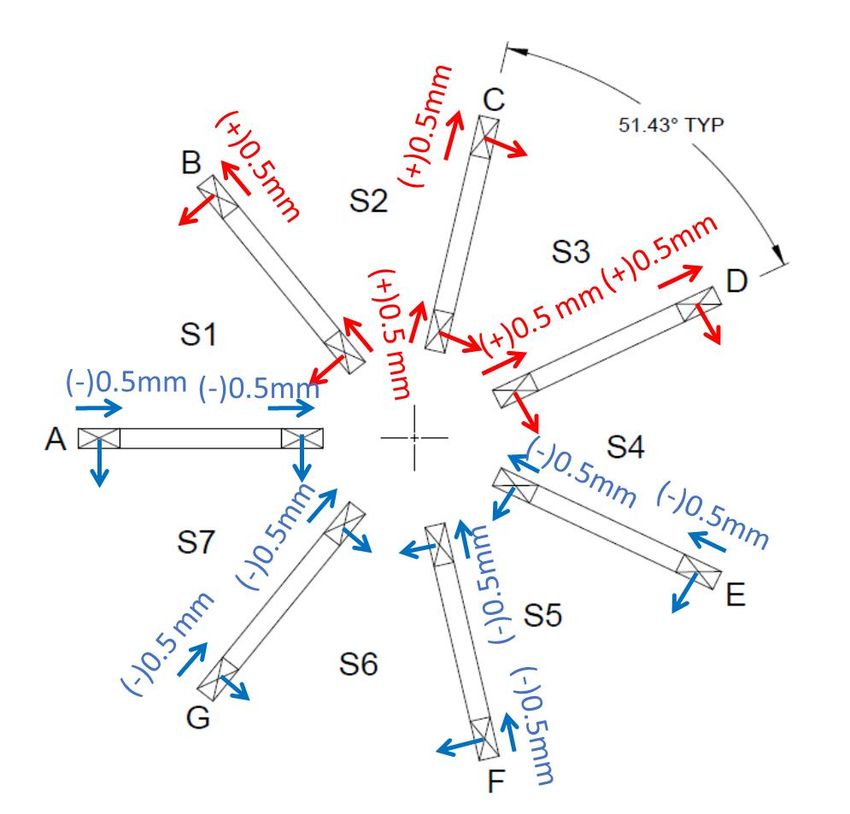
Alignment Tolerance Cases
 Physics worst case
 • All coils offset in same direction (without us
 knowing)
 • Least likely (survey, tracking)

 BEAM worst case is coils aligned in a “conspiratorial”
 way within tolerances
 → induces dipole
 • affects beamline shielding (dose on coils)
 • backgrounds from end of hall apertures
 • Irradiation
 CASE 1 CASE 2 and 3
 Several offset cases considered:
 Beampipe for SAMs 1. All sub-coils offset to induce maximum dipole
 OD 400 mm within allowed tolerances
 2. All subcoils offset without deformation and to
 ±0.5 mm
 3. Same as case 2, but dipole field has different
 orientations in each subcoil

 April 21, 2021 End of Hall MOLLER Forum 12
Stray fields in beampipe deflect e±
 Looking downstream
 10-6
 e- e+
 +
 ×
 ×
 −

 Worst case scenario
Consider the horizontal coil, in the perfectly symmetric case
• all velocity in the z-direction • e- will be bent to the right
• field is vertical along the x axis, (mid-plane of coil) • e+ will be bent to the left
 (onto the coil)
• just off the axis,
 • the field direction is dramatically different
 • e± would feel both horizontal and vertical components of force
 • dispersed Looking upstream

 April 21, 2021 MOLLER Forum 13
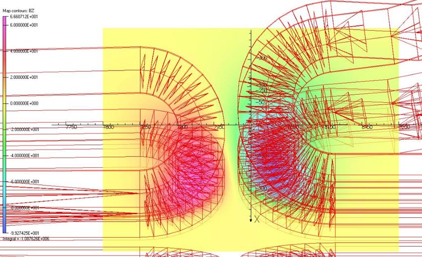
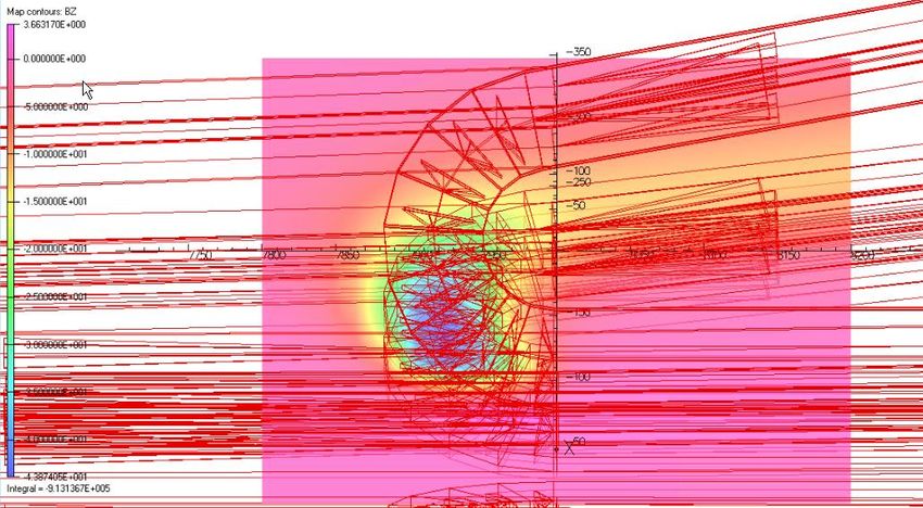
Beam backgrounds - nominal (symmetric) case
 Looking upstream Beampipe intrusion for the SAMs
 Looking downstream (~0.5m upstream)
 symmetric
 Limiting aperture in dump tunnel
 (~0.5 m downstream)

 Dump entrance flange
 (same z location as plots)

 Rate distribution
 Symmetric coils, w/o SAMs for a slice along
 radius

• In the top left plot you see a picture of the ds coils at a particular
 z location with the magnetic field contours and vectors

• Middle top plot is a 2D rate distribution at the entrance to the
 dump tunnel
• To the right is a 1D distribution of the rate in horizontal septant
 (1); the vertical lines indicate the radius of various apertures
 April 21, 2021 MOLLER Forum 14
Beam backgrounds - worst case
 Looking upstream Beampipe intrusion for the SAMs
 Looking downstream (~0.5m upstream)

 Worst case scenario
 Limiting aperture in dump tunnel
 (~0.5 m downstream)

 Dump entrance flange
 (same z location as plots)

 Rate distribution
 for a slice along
 radius
 Case 1, no SAMs/shield

• In the top left plot in the worst case scenario there is an induced
 dipole field > 100 G over most of the area inside the coils

• In this particular orientation, the electrons are bent upward into
 septant 2

• To the right is a 1D distribution of the rate in the worst septant
 (2); even in the worst-case scenario the beam is mostly clearing
 April 21, 2021 MOLLER Forum 15
Comparison of cases
 Symmetric coils, no SAMs
 Case 1, no SAMs/shield

 Symmetric coils, w/ SAMs
 Case 2, w/ SAMs/shield
 Case 3, w/ SAMs/shield
 Symmetric coils, w/ SAMs Case 1

Total Beam Power 715 kW Integrated Power from
 200 mm < r < 600 mm Case 3 Case 2
 Symmetric coils, no SAMs 38.1 W
 Case 1, no SAMs/shield 260 W
 Most likely worst case is 10-4 of total beam power
 Symmetric coils, w/ SAMs 13.4 W
 Case 2, w/ SAMs/shield 17.8 W order of magnitude lower for most likely case
 Case 3, w/ SAMs/shield 14.2 W
 April 21, 2021 MOLLER Forum 16
Power deposition in the epoxy – doses
radius (mm)

 SC4 The power deposition in the epoxy (plot to the upper left) is
 Max 7.4 MGy calculated in a volume of G10 in the simulation
 (G10) • fills the “window”
 SC3 • surrounds the conductor (1 mm thick)
 SC2 • volume of epoxy varies from pixel to pixel
 SC1

 There are shields along the beamline (see bottom left picture)
 that have NOT YET been optimized to reduced the resulting
 doses
 Max 70 MGy (epoxy)
 Subc Max
 z (mm) The G10 filler in subcoils 2-4 have oil Dose
 Preliminary location of cylinders maximum doses of < 1MGy (MGy)
 1 70
 2 34
 width of coil 3 41
 In subcoils 1, 3 (a and b) and 4 +2 epoxy layers
 April 21, 2021 MOLLER Forum 4 22
 17
Positrons in the middle

Phi = 12 degrees
50 < E < 1100 MeV (steps 200 MeV > 100
6 < th < 22 mrad (steps of 2)

Colored by energy (MeV)

0.1 purple
50 cyan
300 green
700 orange
1100 red

Which ones are the most important?

Produce plot of Edep weighted Escatt vs. radius to
see what the most important tracks are
 April 21, 2021 MOLLER Forum Max 320 18MGy
Positrons at the nose

Phi = 12 degrees
E = 0.1, 1, 10, 50 MeV
6 < th < 22 mrad (steps of 2)

Colored by energy (MeV)

0.1 purple
50 cyan
300 green
700 orange
1100 red

 April 21, 2021 MOLLER Forum Max 60 MGy
 19
Field map tests – granularity and extent
 For the downstream torus,
 the map extends from:
 0 < r < 40 cm
 4.5 < z < 12.5m
 Full azimuth

 The spacing is:

 Radial 0.5 mm
 Azimuthal 3◦
 Along z 10 cm

 The field maps are generated in
 z scale 1/10 TOSCA with a Biot-Savart calculation
 (assumes no non-linear materials)

 April 21, 2021 MOLLER Forum 20
Outstanding questions for physicists
 • Field map and interpolation tests
 • Extent – can/should it be smaller than 75 cm in the downstream?
 • Coarseness of grid – probably okay; want to test the limits, optimize
 • Interpolation – default is linear interpolation, investigating cubic as well
 • Dose reduction on epoxy
 • Downstream – absolutely possible; just needs to be done
 • Upstream – needs careful design
 • Effects of offset coils – needs to be considered in every study
 • Tolerable vacuum level determination – beamline backgrounds
 • Dipole field specification – depends somewhat on some of the things above
 • Field measurement system needs
 • Continued iteration with JLAB and MIT engineers

 April 21, 2021 MOLLER Forum 21
Backups
Simulations
 • Core
 • Shielding
 • (target – semi-done)
 • Spectrometer
 • Coil dose, coil shielding
 • Collimation
 • Early (semi-done)
 • Background stuff
 • Asymmetric coils
 • Beamline backgrounds (absolute rate)
 • Clean transport to the dump (beamline elements need to be in the simulation)
 • 1 Torr on beamline
 • Ferrous materials (bellows)
 • Lintels and collars

 • Projects
 • Detector tiling
 • Pion
 • Sams
 • Tracking
 April 21, 2021 MOLLER Forum 23
Deconvolution
 • Although we call the rings moller or ep
 rings, we actually use more than one
 ring to determine the moller asymmetry
 • We will use the different contributions of
 the rate and asymmetry for each of the
 processes in each of the detector tiles to
 “deconvolute” the asymmetries for each
 process
 • Need measurements to benchmark
 simulation
 • Tracking system – low current runs
 • Magnet current scans
 • Alternate beam energies?
 • Should do further studies to test this
 procedure to determine if additional
 systematic measurements are needed

 April 21, 2021 MOLLER Forum 24
Fields and particle tracks
 Side view of =0 field and tracks Tracks are 6 and 21 mrads for both ep and
 (center of open septant) mollers, from 3 different parts of the target

 Tracks have energy/angle correlation, but not
 the radiative effects in the target
 detector plane
 z=2650cm

 • Dashed lines indicate the extent
 2D rate
 of a single septant 1D radial dist., all
 • Transport through the magnets ep includes rad. eff.
 causes the moller “envelope” to moller
 be azimuthally defocussed
 • The add’l segmentation in
 moller ring allows for
 monitoring of systematics
Red – “open” sector
Blue – closed sector
 • Require 20% less up to 10%
Green – transition sector higher current for background
 determination
 April 21, 2021 MOLLER Forum 25
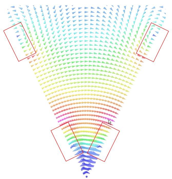
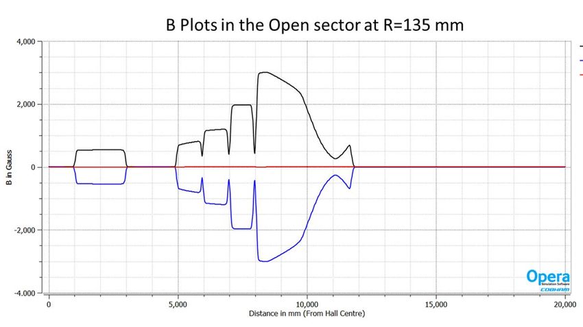
Shape of field in a septant – varies along z, and also along r and
 z=9500mm • Vector map colors show relative total field strength in a septant
 azimuthal de-
 focusing • Radial components of field cause azimuthal (de-)focussing near
 the conductor at the (outer) inner radius of the conductor
 o Provides required inelastic electron separation
 o Causes mid-angle mollers to fill full azimuth at detector
 • Field varies along z to separate the low E moller and high E eps

 BMOD
 Bφ
 azimuthal focusing Bz

 B (Gauss)
 R=135mm

 z=9500mm

 = in the direction
 April 21, 2021 2 MOLLER Forum 26
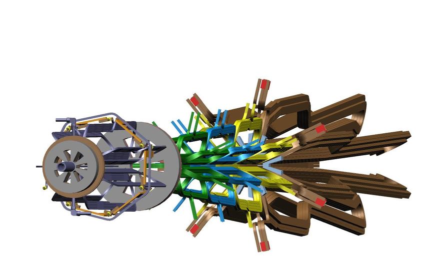
Keep Out Zones – showing coils in one septant - notional
 SIDE VIEW
 Acceptance 5x MS radius cones
 defined by
 collimator 2
(IPE by coll. 1)

 Cross-section at z=6000 mm

 photon
 LOOKING DS At upstream end, tracks go between
 envelopes conductor, so can only fill half
 outer and inner
 azimuth with conductor or supports

 • Need to avoid interfering
 with the accepted electrons
 elastic e-p envelop
 (maximize signal, simply LOOKING DS
 defined angular acceptances)
 • Also need to avoid interfering
 with the photon envelopes At downstream end, tracks are bent
 moller e-e Coils and supports (reduce backgrounds) to a larger radius than the conductor,
 in each septant
 envelop so can fill the full azimuth
 April 21, 2021 MOLLER Forum 27
PDR Summary
The spectrometer system must
 • The acceptance of the moller electrons is
 defined at collimator 2
 • Achieve the physics optics (bend particles) by
 • The shape of the coils and the specified
 o defining the angular acceptance in a well- tolerances achieve the physics optics
 defined way • Field stability requirements modest due to
 averaging over time and cancellation b/c
 o separating the moller and elastic ep electrons measuring asymmetry
 o providing 3 kinematic regions of the inelastic
 electrons (to deconvolve the asymmetries)
 • Shield the experiment by • Collimator 1 defines the primary beam
 through experiment to the dump
 o minimizing the backgrounds at the detector • Coils and supports obey > 5x multiple
 scattering radius by design
 o reducing the conductor epoxy and G10 filler
 dose from excessive radiation to acceptable • The collimators, lintels and beam shields are
 all designed to minimize the backgrounds at
 levels the detector plane
 o ensuring clean transport of the primary beam • The shielding will be optimized* to shield the
 coil epoxy/ G10 filler as well to maintain
 to the dump shear and compressive strength
 • Operate for a long running time (344 PAC days) *The downstream coil conductor will not require modification to
 accommodate any of the proposed updated shielding configurations
 April 21, 2021 MOLLER Forum 28
Procedure for testing conductor configs
 • JLAB produces conductor config (blocky version of CAD)
 • Juliette reads in the conductor, produces map in TOSCA
 • Sakib reads map into GEANT4 to run sims/do analysis

 Purpose: to check whether reasonable changes to the segmented to improve engineering make a difference to
 the downselect

 V1U.2a_V1DSg.3

 V1U.2a_V2DHy Configuration
 V1U.2a_V2DSg.1a labels

 V1U.2a_V2DSg.1b

 April 21, 2021 MOLLER Forum 29
Direct comparison of fields Approximate path of
 moller tracks
 V1DSg.3
 Radially focusing comp. (BY)
 Center of open sector

 -0.29 T
 0T

 V2DHy

 -0.29 T

April 21, 2021 MOLLER Forum 30
all
 Moller open

 Elastic

 Inelastic Radial distributions
 by process in the
 different sectors

 trans closed

April 21, 2021 MOLLER Forum 31
Default

 2D distributions at
 detector plane

 Moller: Ring 5
 V1U.2a_V1DSg.3 V1U.2a_V2DHy
 Elastic ep: Ring 2

 Red: Open
 Blue: Closed
 Green: Trans.

April 21, 2021 MOLLER Forum 32
 V1U.2a_V1DSg.1a V1U.2a_V1DSg.1b
 -r distributions at
 detector plane

 Approximate radial
 V1U.2a_V1DSg.3 V1U.2a_V2DHy
 ring def’ns shown

 Moller: Ring 5
 Elastic ep: Ring 2

April 21, 2021 MOLLER Forum 33
 V1U.2a_V1DSg.1a V1U.2a_V1DSg.1b
moller
 elastic
 inelastic

 distributions at
 detector plane

 V1U.2a_V1DSg.3 Approximate radial V1U.2a_V2DHy
 ring def’ns shown

 Moller: Ring 5
 Elastic ep: Ring 2

April 21, 2021 MOLLER Forum 34
 V1U.2a_V2DSg.1b V1U.2a_V2DSg.1b
Deconvolution study summary
 Relative uncertainty
 Process V1U.2a_V1DSg3 V1U.2a_V2DHy V1U.2a_V2DSg.1a V1U.2a_V2DSg.1b
 Primaries only

 Møller 0.0211 0.0210 0.0212 0.0211
 e-p Elastic 0.0577 0.0560 0.0515 0.0614
 e-p Inelastic (W1) 0.1294 0.1529 0.1249 0.1370
 e-p Inelastic (W2) 0.0673 0.0681 0.0638 0.0709
 e-p Inelastic (W3) 0.1706 0.1658 0.1662 0.1742
 Møller 0.0214 0.0214 0.0217 0.0215
 Secondaries

 e-p Elastic 0.0631 0.0618 0.0560 0.0680
 e-p Inelastic (W1) 0.1495 0.1779 0.1413 0.1576
 e-p Inelastic (W2) 0.0804 0.0823 0.0752 0.0876
 e-p Inelastic (W3) 0.2309 0.2279 0.2313 0.2420
 Segmented Hybrid Alternate Segmented

 • The relative uncertainty on the moller asymmetry is • Changes for engineering concerns do affect the focal
 the same between hybrid and segmented plan distributions
 • There is no significant difference between the hybrid • Adjusting the detector tiling allows us to achieve the
 and segmented from a physics perspective same relative uncertainty on the moller asymmetry
 • a slight preference for the segmented Recommend segmented configuration as new baseline
 April 21, 2021 MOLLER Forum 35
5 process deconvolution (Using only primaries)

 V1U.2a_V1DSg.3 V1U.2a_V2DHy

 April 21, 2021 MOLLER Forum 36
 V1U.2a_V2DSg.1a V1U.2a_V2DSg.1b
5 process deconvolution (including secondaries)

 V1U.2a_V1DSg.3 V1U.2a_V2DHy

 April 21, 2021 MOLLER Forum 37
 V1U.2a_V2DSg.1a V1U.2a_V2DSg.1b
Conclusion
 • The relative uncertainty on the moller asymmetry is the same between hybrid
 and segmented (0.0214)
 • There is no significant difference between the hybrid and segmented from a
 physics perspective
 • a slight preference for the segmented
 • Changes for engineering concerns do affect the distributions at the detector
 plane
 • Adjusting the detector tiling allows us to achieve the same relative
 uncertainty on the moller asymmetry (0.0217, 0.0215)

 Recommendation: segmented
 configuration as new baseline

 April 21, 2021 MOLLER Forum 38
W plate • Default: Use Chandan’s 2-bounce shield (black),
 the merged collimator 1+2, and the extended
 Chandan’s 2-bounce shield 2mm thick W plates
 Naz’s 2-bounce shield
 Front coil • Try larger region near hottest spot (reproduce
 shield the table – check dose calculations, use larger
 region for more statistics)

 New sims:
 Nose shield extension • Nose shield
Outer nose shield • Inner nose shield Radial thickness,
Inner nose shield length along z
 • Outer nose shield
 • Nose shield extension

 11mm thick • Different thickness and material for 2 bounce
 shield (dose vs different thickness)
 2 mm thick • Different W plate thicknesses (how does 1 or
 1.5 mm work)
 11mm thick

 April 21, 2021 MOLLER Forum 39
Collimator/epoxy shield updates
 • Col 1+2 merge (fins were a source of rate at upstream coil)
 • Upstream region shielding (W plates and nose shield)
 • Downstream region
 • coll 5, 2-bounce/septapus, e ± spokes

 April 21, 2021 MOLLER Forum 40
Power deposition in the us epoxy Appendix

 2 mm tungsten plating (both sides of coil)
 factor of ~8 suppression of middle hot spot

 / ∙ 7.42 × 106 =

 estimate of maximum dose:
 5 ∙ 7.42 × 106 = 37 MGy

 April 21, 2021 MOLLER Forum 41
What about the ds toroid? Appendix

 in coil segment 3, the approximate
 volume of epoxy in a “hot region” pixel is

 2 × 4 × 20 2
 + 33 × 1 × 20 2
 = 820 3

 Estimate of maximum dose:

 13.6 ∙ 1.81 × 106 = 25 MGy

 April 21, 2021 MOLLER Forum “middle” hot region 42
Epoxy Resin tolerance to radiation

 Recommendation by
 R. Fair, 08.15.20, after review of reference materials by D. Kashy and E. Sun

 Table shows shear strength of glass cloth and Shear strength of Cu
 copper, impregnated with CTD403 @ 70oC Radiation Dose
 Unprimed Primed
 Comparing cases with the copper both PRIMED 0 MGy 43.6 MPa 71.9 MPa
 and UNPRIMED with CTD450 60 MGy 37 MPa 61 Mpa*

 Irradiated shear strength with priming: higher → (i.e. a 15 % reduction)
 than unprimed, unradiated CTD403

 * Using the same 15 % reduction in strength

 April 21, 2021 MOLLER Forum 43
100% Azimuthal Acceptance Possible
 21 mrad

 9.5 mrad

 6 mrad

 Acceptance defining
 collimator

 Lab Frame Detectors in
 e-
 2 < E’ < 8 GeV
 open sectors
 6 < θ < 21 mrads
 e-

 e- e- e-

 Forward and backward (in
 e-
 COM) scattered electrons from
 two events (line type links Coils in closed sectors
 electrons from same event)
 Any odd number of coils will allow for 100% acceptance

 April 21, 2021 MOLLER Forum 44
Conductor Layout (Current Distribution) Appendix

 April 21, 2021 MOLLER Forum 45
Collimators Appendix

 Collimators and beam shields are designed to Pb rings at large radius downstream are
 provide a 2-bounce system to eliminate line of sight to shield detectors from bkgds
 photons to detectors

 In addition, “blockers” at collimator 2 will
 Collimator 1 – water-cooled be used for systematic studies
 Collimator 2 – precision machined
 5
 4, 5 are “clean-up collimators”
 4

 2
 1

 April 21, 2021 MOLLER Forum 46
Finite Target Effects Appendix

 • The acceptance varies along the length of the target
 • Requires mapping with the tracking system θhigh,down
 Expected Q2 distribution Router θhigh,up
 θlow,down

 θlow,up

 Rinner

 ztarg,up ztarg,center ztarg,down
 ztarg,up = -75cm
 ztarg,center = 0cm
 ztarg,down = 75cm θlow,cen = 6.2mrads
 θhigh,cen = 19.2mrads
 θlow = 5.5mrad Rinner = 3.658cm
 θhigh = 17mrad Router = 11.306cm
 θlow,down = 7.1mrads
 θhigh,down = 21mrads
 zcoll =590cm
 April 21, 2021 MOLLER Forum 47
Sector Orientation Appendix

 Closed sector to beam left to shield
 synchrotron radiation from hall A
 arc

 Horizontal coil

 April 21, 2021 MOLLER Forum 48
Effect of returns In this septant: ~ Radially focussing ~ Azimuthally focussing The component of the field that is most different is the z component − − Ƹ Ƹ Ƹ • Only applied for a short distance (x10 reduction) Ԧ = Ԧ × = − = − − Ƹ • Only act on vr component (x100 reduction) • Is small – 10-100x smaller than radial focussing − − component , ≪ • 1e4 – 1e5 reduction in strength April 21, 2021 MOLLER Forum 49
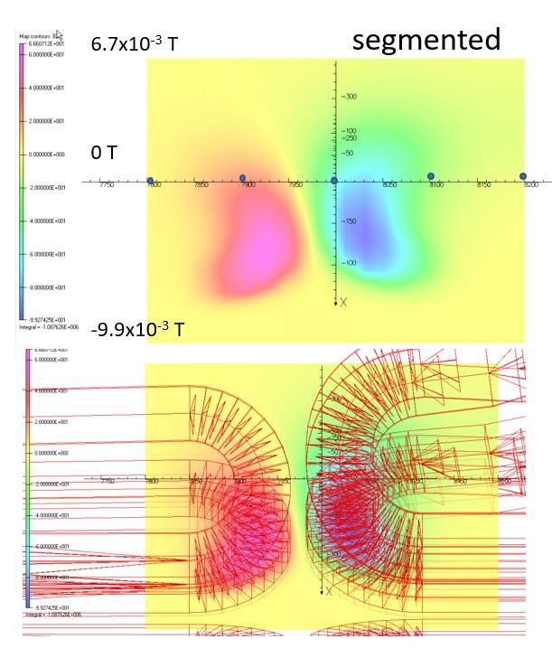
Z component of the field
 segmented 3.6x10⁻⁴ T hybrid
 6.7x10⁻³ T
 0T

 0T

 -9.9x10⁻³ T -4.3x10⁻³ T

 April 21, 2021 MOLLER Forum 50
Fields along φ @ z=1350 cm for different r Appendix

 component “sags” in the center
 of the septant from the ideal case

 Bφ(13.5 cm)
 Br(13.5 cm)
 Br(29 cm)
 z = 1350 cm Br(9 cm)

 component changes sign at the edges
 of the septant at the inner and outer
 radii

 April 21, 2021 MOLLER Forum 51
Fields along r @ z= 1350 cm Appendix

 BMOD
 z = 1350 cm Bø
 center of open Br

 BMOD
 Bø
 z = 1350 cm Br
 edge of open

 April 21, 2021 MOLLER Forum 52
Fields along z @ r = 13.5 cm Appendix

 BMOD
 r = 13.5 cm Bz
 center of open

 Bz at edge
 Bz center
 r = 13.5 cm
 edge of open
 non-zero z components
 near current returns
 (included in field maps)

 April 21, 2021 MOLLER Forum 53
2 bounce code Appendix

 • Python code
 • Target, collar, collimators, beam shields, detector (600, 690-1300 mm)
 • Uses straight lines to simulate an isotropic source (with
 sees the random position, angle)
 target
 • Surfaces that “see” the target (red) become new sources from target
 sees 1-bounce
 • Tolerance study 1-bounce source
 • move the collimators and/or coils by +/- 1 mm w/o seeing green on the detectors

 Proper beam shield

 April 21, 2021 MOLLER Forum 54
Root script Appendix

 Moller/ep
 Line of sight

 Detector plane

 Collars moller

 ep

 DS beampipe
 Collimators Lintels
 12 4
 Outer Photon Envelope

 Inner Photon Envelope

 Target
 April 21, 2021 MOLLER Forum 55
Phase space study
Detector z
 “Back of envelop” tracks

 TOSCA tracks

April 21, 2021 MOLLER Forum 57
1. Get , Back of the envelop calculations from TOSCA (n-dimensional envelop) 2. Calculate • Each segment gives a “kick” at the central z 3. Get r in next location segment • Field integral depends on radius of the track in 4. Drift to that segment and the length of the segment detector , [ ]∆ • Radius in a given segment depends on fields of = upstream magnet segments 3.33 [ ] • The radius at the upstream magnet depends on the scattering angle and target z, then iterate ∙ ℓ [ ] [ ] = 3.33 [ ] −1 = −1 + tan + =0 2 1 0 0 1 2 April 21, 2021 MOLLER Forum 58
Combining kicks 1 = 0′ + 1 tan ′ 0 = 0 tan = 0′ tan ′ 0 = ′ + 1 tan ′ tan = 180° − − 0 1 = 0 + 1 tan ′ ′ = 180° − = 0 + 1 tan + 0 = + 0 0 −1 0 0 = −1 + tan + ′ =0 0′ 0 1 April 21, 2021 MOLLER Forum 59
Exploring the parameter space

 Steps:

 1. Modify the hybrid
 (usually making several settings with a given change)
 2. Run tracks in TOSCA
 3. Compare detector plane distributions to those for the nominal hybrid
 4. If something is promising, make field maps (usually for several settings)
 5. Run simulations in GEANT
 6. Look for Moller and elastic ep rates, asymmetries and background percentages

 8 (2.11)

 April 21, 2021 MOLLER Forum 60
Exploring the parameter space
 Plot field factor of one segment vs. field factor of another segment
 and weight by the quantity of interest

 56 = 15625 combinations

 B2=1.0 because it is very shallow
 Reduces the number of plots to show

 B0 = 1.0
 B2 = 1.0
 Dark Blue < epfocus < Red
 0 cm < epfocus < 12 cm

 April 21, 2021 MOLLER Forum 61
eefocus epfocus

 Upstream Field Factor

 Upstream Field Factor
 worse worse

 Hybrid Field Factor Hybrid Field Factor

 Plots of focus (top) and peak separation
 eeepsep

 Upstream Field Factor
 (bottom) in cm for different scale factors
 for the upstream vs. downstream field

 eefocus - 0-16 cm,
 red is worse worse
 epfocus - 0-12 cm,
 eeepsep - 15-23 cm red is better

 Better focus and separation for higher
 current densities in hybrid torus
April 21, 2021 MOLLER Forum 62
 Hybrid Field Factor
You can also read