Bakerloo line extension - Information for Developers April 2021 - Transport ...
←
→
Page content transcription
If your browser does not render page correctly, please read the page content below
Bakerloo line extension

Information for Developers
April 2021
Bakerloo line extension
Information for Developers
April 2021
Document Number: BUE4100-TFL-MAC-B001-REP-ZZ-00001
Bakerloo line extension - Information for Developers BUE4100-TFL-MAC-B001-REP-ZZ-00001

Contents
 Introduction ................................................................................. 4
 General Information.................................................................... 6
 Ground Movement ...................................................................... 9
 Operational Noise and Vibration .............................................. 10
 Engagement with the Bakerloo line extension ......................... 12
 Bakerloo line extension Planning Conditions ........................... 15
Appendix A .................................................................................... 17
Appendix B .................................................................................... 33

 Page 3 of 42
Bakerloo line extension - Information for Developers BUE4100-TFL-MAC-B001-REP-ZZ-00001

 Introduction
1.1 This document provides guidance from Transport for London (TfL) relating to
 developments planned to commence or be completed prior to the commencement of
 construction of the Bakerloo line extension (BLE) and located within the Safeguarding
 Limits shown on the plans accompanying the Bakerloo line extension safeguarding
 Directions issued by the Secretary of State for Transport on 1 March 2021 (Directions).

1.2 Under Directions, local planning authorities (LPAs) are required to consult TfL before
 determining any application for planning permission for development wholly or partly
 within the Safeguarding Area (see paragraph 3 of the Directions). The Directions also
 specify that in certain cases applications do not have to be referred to TfL (see
 paragraph 4 of the Directions).

1.3 The purpose of the Directions is to protect the BLE by ensuring that any planning
 applications for development that may affect the BLE are considered by TfL and that
 the Secretary of State is given an opportunity to intervene if the LPA does not intend
 to follow the recommendation of TfL in determining the application. Examples of such
 developments include new construction on vacant sites, complete or partial
 reconstruction on existing or larger site area, enlargement of basements, increase in
 building height or density, new or modified foundations and changes of use involving
 increased sensitivity to noise and vibration, e.g. commercial to residential.

1.4 An applicant for planning permission ought to be able to demonstrate that the
 foundations of development proposals would not obstruct the route of the BLE tunnels
 or adversely impact on the construction, design or operation of the tunnels, stations
 and other infrastructure related to the BLE. Developments should also be designed to
 avoid TfL incurring any excessive additional cost in constructing or operating the BLE.
 If an applicant cannot satisfy TfL on these matters, then TfL is likely to recommend
 that planning permission is refused or granted subject to a condition or conditions
 (and/or a planning obligation) that protects the BLE.

1.5 New developments should be designed to accommodate the construction and
 operation of the BLE. The potential effects on developments include ground
 movements during construction and noise and vibration during both construction and
 railway operation. The railway is designed to achieve a 120-year design life that may
 well exceed the design life of building projects. Developers’ designs must also take
 into account and demonstrate that the integrity and operability of the BLE assets will
 not be prejudiced as a consequence of the demolition of the development in the future.

1.6 As part of the consultation process on planning applications under the Directions, TfL
 can:

 a) Make no comment

 b) Recommend that the LPA place conditions on a planning permission to ensure
 that the delivery and operation of the BLE are not prejudiced (see further Section
 6 below)

 Page 4 of 42

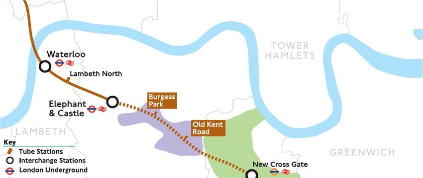
Bakerloo line extension - Information for Developers BUE4100-TFL-MAC-B001-REP-ZZ-00001

 c) Recommend that the application be refused

1.7 Guidance on the BLE design assumptions is set out in this document. They aim to
 assist developers in ensuring that new development does not affect the construction
 or operation of the BLE and that the development itself is not unduly affected by the
 construction and operation of the BLE.

1.8 TfL welcomes early dialogue with developers about the design of developments and
 upon planning conditions that might be appropriate in respect of them. Development
 agreements may be appropriate in some circumstances.

1.9 The Directions do not require TfL to be consulted prior to permitted development under
 the Town and Country Planning (General Development) (England) Order 2015 being
 carried out. However, TfL would welcome approaches from developers for such works
 where it is considered there could be an impact on the BLE. The LPAs work with TfL
 and should be able to advise, where development proposals are not referable to the
 Mayor and TfL, of the need or otherwise to engage with TfL. Nonetheless, for the
 avoidance of doubt, if you have general queries about the BLE Safeguarded Area
 please refer to railwaysearches@tfl.gov.uk. To make enquiries about any other aspect
 of the BLE please contact ble@tfl.gov.uk.

 Figure 1: 2019 Consulted Route Proposal to Lewisham via Old Kent Road and New Cross Gate

 Page 5 of 42
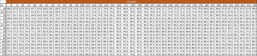
Bakerloo line extension - Information for Developers BUE4100-TFL-MAC-B001-REP-ZZ-00001

 General Information
2.1 Tunnel size

 The BLE will be building two running tunnels along the route, with cross passages
 located at regular intervals. These will be located within the Safeguarded Area.

 The excavated diameter of the BLE running tunnels should be taken as 6m, with an
 internal diameter of 5m (see Figure 2).

 The diameter of cross passages, station platform escalators, ventilation and other
 tunnels and shafts varies. The location and size of these tunnels and shafts will be
 subject to further design development. The developer should contact the BLE
 Safeguarding Manager for further advice on this issue, details are provided in Section
 5 of this document.

2.2 Tunnel exclusion and construction tolerance zones

 Depending on the stage of design development at the time of the request, details of
 the BLE tunnels and other infrastructure will be provided by the BLE Safeguarding
 Manager. It should be noted, however, that the BLE infrastructure could be in any
 position both horizontally and vertically within the Safeguarded Area.

 The following criteria will apply to the BLE tunnels in particular locations:

 a) Developers should note that an “Exclusion Zone” will exist around all tunnels. For
 each running tunnel, see Figure 2, this Exclusion Zone (13m wide and 16m high)
 corresponds to the area of sub-soil that BLE would seek to acquire under the terms
 of the enabling Transport and Works Act Order (in effect, the instrument by which
 planning consent is given). The Exclusion Zone is required to safely construct,
 operate and maintain the BLE. Foundations and temporary works may not
 encroach into the Exclusion Zone unless otherwise agreed with TfL. The Exclusion
 Zone includes a 0.5m tunnel “Construction Tolerance Zone” giving a total of 3.5m
 both sides and to the bottom of the tunnels and 6.5m above the tunnels. Special
 forms of foundation construction (e.g. widely spaced heavily loaded under-reamed
 deep piles) may require a greater vertical separation. In these cases, the
 developer will need to assess the minimum separation that will ensure the
 construction or operation of BLE nor the development itself is prejudiced.

 b) TfL will retain the flexibility to move the tunnels 3m in either direction horizontally
 and a minimum of 1m vertically upwards. This is referred to as the “Alignment
 Adjustment Zone” and the design of any new development should take account of
 this possible deviation. Developers should discuss this with the BLE Safeguarding
 Manager. The Alignment Adjustment Zone is required to retain flexibility to amend
 the BLE alignment within the Safeguarded Area to avoid potential obstructions or
 other alignment constraints as the tunnel design evolves. Figure 2 identifies these
 zones on an indicative section, showing one tunnel.

 Page 6 of 42
Bakerloo line extension - Information for Developers BUE4100-TFL-MAC-B001-REP-ZZ-00001

 c) The developer must make adequate allowance for the construction tolerance of
 their proposed development foundations in determining their proximity to the BLE
 tunnels.

 d) Depending on the stage of design development, in certain locations there may be
 scope for discussing the extent to which paragraphs a to c above apply. The BLE
 Safeguarding Manager will advise the developer accordingly.

 Figure 2: Indicative cross section showing a BLE running tunnel, Exclusion Zone and Alignment Adjustment Zone

2.3 Stations, shafts and other areas of surface interest.

 The BLE will also be constructing buried station box structures and ventilation and
 emergency services access shafts at several locations. Developers will be required to
 consider the impact of their proposals on these station box structures and shafts in a
 similar manner to the BLE tunnels, especially with regards to foundations and
 temporary works. The developer should seek advice from the BLE Safeguarding
 Manager (refer to Section 5 for details) regarding the particular constraints imposed

 Page 7 of 42
Bakerloo line extension - Information for Developers BUE4100-TFL-MAC-B001-REP-ZZ-00001

 by these structures. This includes constraints linked to BLE-related emergency
 access/egress and ventilation.

 The developer must make adequate allowance for the construction tolerance of their
 proposed development foundations and/or temporary works in determining their
 proximity to the BLE station box structures and shafts.

2.4 Loads from development foundations

 Development foundations must be designed so that changes in stress in the future
 tunnel linings do not exceed acceptable levels. Changes in stress due to foundations
 or basements shall be considered.

 In general, this will be achieved if the overall loading imposed on the tunnels:

 a) Does not exceed the existing ground overburden plus the loading from any
 existing development (as would be the case for redevelopment of an existing site)

 b) Does not exceed the existing ground overburden plus 50kN/m2 imposed at ground
 level over the footprint of the development (as would be the case in development
 of a vacant site)

 The BLE tunnels will be designed to account for existing loads.

 In the assessment of overall loading, the reduction in overburden arising from
 provision of a new basement, tunnel or other subsurface construction beneath the
 development can be taken into account to offset increased surcharge from the
 development.

 Page 8 of 42

Bakerloo line extension - Information for Developers BUE4100-TFL-MAC-B001-REP-ZZ-00001

 Ground Movement
3.1 Construction of the BLE portal, tunnels, shafts and station boxes has the potential to
 cause movement of the ground adjacent to these structures. The foundations of new
 developments (or modification to the foundations or basements of an existing
 development) should therefore be designed so that damage to the development from
 this settlement does not exceed acceptable levels.

3.2 TfL uses a methodology to calculate ground movement which has been used on
 numerous projects (e.g. Jubilee Line Extension, Channel Tunnel Rail Link (HS1),
 Crossrail) and has been found to be a reliable approach to estimating ground
 movement. The method TfL uses to calculate ground movement is described in
 Appendix A. The developer may wish to use the same methodology, although TfL
 cannot accept any responsibility for its use, and use of the methodology should not be
 taken as guaranteeing that TfL will recommend a planning application is granted (or
 planning conditions are not required).

3.3 The face losses from BLE tunnelling will not exceed 1.2% for 6m diameter running
 tunnels, this value is based on back-analysed results from Crossrail. For all other
 tunnels, including those constructed by SCL (sprayed concrete linings), percentage
 face losses from tunnelling will not exceed 1.5%. These face loss values of 1.2%
 (running tunnels) and 1.5% (all other tunnels) should be used in any ground movement
 assessments.

 Page 9 of 42
Bakerloo line extension - Information for Developers BUE4100-TFL-MAC-B001-REP-ZZ-00001

 Operational Noise and Vibration
4.1 As discussed further in Section 5, TfL may recommend the imposition of planning
 conditions to a planning permission. These conditions may in turn require the provision
 of adequate assessments in relation to the interface between operational noise and
 vibration from the BLE and the proposed development, insofar as this information has
 not been provided at the application stage. [Developers should satisfy themselves at
 the application stage that their proposed developments will be capable of proceeding
 subject to such conditions].

4.2 The operation of Bakerloo line trains has the potential to cause vibration to be
 transmitted from the tunnels to the foundations of local buildings which could then be
 re-radiated as groundborne noise within the building. The potential for this effect is
 higher when the foundations are in close proximity to the tunnels.

4.3 The reason for the planning conditions will be to ensure that the proposals for
 development (or modification to the foundations or basements of an existing
 development) within the Safeguarded Area have foundations which are compatible
 with the levels of vibration and groundborne noise generated within the building or
 nearby structures from the operation of Bakerloo line trains.

4.4 The developer should use the information in Appendix B, as developed for the
 Crossrail 2 project, to predict the levels of vibration and groundborne noise in their
 development and ensure any necessary mitigation is in place in order to allow for the
 discharge of the relevant condition.. TfL cannot accept any responsibility for the use
 of this information, and its use should not be taken as guaranteeing that TfL will advise
 the LPA that the terms of the relevant planning condition have been met.

4.5 In accordance with Appendix B:

 The developer should use the assumption that the BLE will adopt an operational track
 system with an equivalent performance to the high-performance standard track used
 by Crossrail (Appendix B gives details).

 The levels of vibration at the tunnel wall caused by the passage of a single train
 travelling at both 100 km/h and 80 km/h for the BLE has been taken as equivalent to
 that modelled for the Crossrail 2 project. These are presented in Table 1 and Table 2
 and graphically in Figure 1 to Figure 4 in Appendix B.

4.6 Details of this noise and vibration assessment, and any necessary mitigation
 measures, should be clearly set out in a noise and vibration report prepared by a
 suitably competent and experienced acoustic consultant with demonstrable
 experience of assessing noise and vibration from the operation of underground rail
 systems. This report should be submitted to the LPA as part of the application to
 discharge the planning condition regarding the BLE, and the LPA will in turn refer it to
 the BLE project team, for consideration.

4.7 The BLE Safeguarding Manager will advise the developer of any issues related to the
 assessment or the building design and liaise with the developer to resolve them. The
 Page 10 of 42
Bakerloo line extension - Information for Developers BUE4100-TFL-MAC-B001-REP-ZZ-00001

 developer may have to submit further information if the report submitted is not
 satisfactory. Once the BLE Safeguarding Manager is satisfied with the information,
 TfL will be able to advise the LPA.it has no objection to a planning condition being
 discharged.

4.8 The developer is strongly recommended to enter into early discussions with the BLE
 Safeguarding Manager about their development proposals prior to finalisation and
 submission of the noise and vibration report.

 Building Level/Measure

 Residential buildings 35dB LAmax,F

 Offices 40dB LAmax,F

 Theatres 25dB LAmax,F

 Hotels 40dB LAmax,F

 Large auditoria/concert halls 25dB LAmax,F

 Sound recording studios 30dB LAmax,F

 Places of meeting for religious worship 1 35dB LAmax,F

 Courts, lecture theatres 35dB LAmax,F

 Small auditoria/halls 35dB LAmax,F

 Hospitals, laboratories 40dB LAmax,F

 Libraries 40dB LAmax,F

 Table 1: Operational Groundborne Noise Design Aims

Notes:
1. Meaning a place the principal use of which is for people to come together as a congregation to worship God or do
reverence to a deity.

 In the Absences of Appreciable Existing Appreciable Existing Levels
 Levels of Vibration of Vibration 1 2

 VDV ms-1.75 Daytime VDV ms-1.75 Night-time % Increase in VDV
 (07:00 – 23:00) (23:00 – 07:00)

 0.31 0.18 40

 Table 2: Operational Vibration Criteria

Notes:
1. Highest impact category used, daytime or night-time.
2. There is an appreciable existing level of vibration where daytime and night-time vibration dose values (VDVs) exceed
0.22 ms-1.75 and 0.13 ms-1.75 respectively.

 Page 11 of 42
Bakerloo line extension - Information for Developers BUE4100-TFL-MAC-B001-REP-ZZ-00001

 Engagement with the Bakerloo line extension
5.1 Developers are encouraged to engage with TfL prior to submission of a planning
 application to the LPA (or an application for a lawful development certificate in the
 case of permitted development), to maximise opportunity for understanding and
 consideration of project interface constraints and opportunities, and in the case of
 planning applications, the conditions which TfL may seek to impose on the
 development in order to manage the impact on, and of, the construction and operation
 of the BLE.

5.2 The principal point of contact for BLE Safeguarding matters is:

 BLE@tfl.gov.uk

5.3 Developers should submit reports and drawings demonstrating their compliance with
 this guidance document. Such reports and drawings, when reviewed and accepted by
 the BLE Safeguarding Manger, will enable TfL to confirm it does not intend to
 recommend refusal and, if relevant, recommend any planning conditions for the
 development under the terms of the Directions.

5.4 In some instances, a development or other legal agreement between the developer
 and TfL may be required. It might also be appropriate for planning obligations to
 include provisions necessary to protect the delivery of the BLE as a pre-requisite to
 planning permission being granted.

5.5 TfL reserves the right to charge developers for time and resource utilised in assessing
 development proposals, particularly where specialist engineering and legal resources
 have to be commissioned to advise. If charges are anticipated, these will be advised
 to the developer before these costs are incurred. The developer will be expected to
 provide its invoicing instructions and a commitment to reimburse TfL before costs are
 expended.

5.6 TfL recommends that evidence is presented in a structured format such as a
 Conceptual Design Submission (CDS) using the approach set out in Appendix A for
 building damage assessment calculations and the approach for noise and vibration
 set out in Appendix B (though, as stated above, TfL does not take any responsibility
 for the use of those appendices, and such use should not be taken as guaranteeing
 that a recommendation will not be made against the development). This will allow TfL
 to examine the assumptions and calculations that have been undertaken in a
 consistent manner across the route. If an alternative approach for the calculations are
 submitted, TfL reserves the right to charge developers for time and resources utilised
 in assessing development proposals, particularly where specialist engineering and /
 or legal resources have to be commissioned. If charges are anticipated, then these
 will be advised to the developer before the costs are incurred. The developer will be
 expected to provide its invoicing instructions and a commitment to reimburse TfL
 before costs are expended.

 Page 12 of 42
Bakerloo line extension - Information for Developers BUE4100-TFL-MAC-B001-REP-ZZ-00001

 TfL recommends that the CDS should follow the layout and sub-headings as set out
 below:

 a) Executive Summary.

 b) Introduction, setting out objectives:

 - That the future construction or operation of the BLE is not prejudiced by the
 proposed building.
 - That the building itself is not adversely affected to an unacceptable degree by
 the construction or operation of the BLE.
 - Stating compliance with terms of a development agreement (if applicable).

 c) Overview, outlining:

 - The nature of the development.
 - Proximity to BLE infrastructure.
 - Assumptions for tunnel diameter, clearance requirements and exclusion
 zones, volume loss and noise & vibration assessment and other criteria as
 set out in this document.

 d) The Parties, including contacts, roles and responsibilities.

 e) Outline Project Programme, including key milestone dates (accuracy
 commensurate with knowledge at planning stage of development).

 f) Summary of assumptions on existing site conditions, to include:

 - Compiled assumptions on ground conditions, groundwater and ground
 contamination (if appropriate) with at least one bore hole log.
 - Details substantiated by desk top assessment or intrusive surveys as
 appropriate, supplied by the developer’s design representatives.

 g) Effects of BLE construction on the proposed development, to include:

 - Summary of predicted settlement damage assessment (using method in this
 document for shallow foundations, if applicable – calculations to be
 appended) and to include a Category 2 check.
 - Summary of noise & vibration assessment (using method prescribed).

 h) Standards and References.

 i) Quality Control sheet, signed by compiler, checker and director (or senior
 manager).

 j) Appendices:

 - The drawings to include plans, cross sections and long sections as
 appropriate, showing the relationship between the development and the
 proposed position of the BLE as advised by the BLE Safeguarding Manger.

 Page 13 of 42
Bakerloo line extension - Information for Developers BUE4100-TFL-MAC-B001-REP-ZZ-00001

5.7 The developer’s design should be submitted using the London Survey Grid format,
 converted from Ordnance Survey National Grid. LSG Height Datum (LSGH) shall be
 used. The datum level is set at approximately 100m below OS datum at Newlyn.

5.8 Provision of the required reports can be phased if this suits the developer’s design
 programme and TfL will recommend part discharge of planning conditions as
 appropriate.

5.9 Reports should be in digital format sent by email. File sharing via methods such as
 “We Transfer” is not acceptable. A hard copy may be required.

5.10 On completion of construction, as-constructed drawings of the foundations (including
 schedule of pile toe levels), left in place temporary works and site plan, all in digital
 format should be provided to TfL. Details of work above ground level are not usually
 required.

5.11 It would be helpful if the developer contacts the BLE Safeguarding Manager if it is
 decided not to proceed with development, or the start date is delayed by over 6 months
 from that originally advised.

 Page 14 of 42
Bakerloo line extension - Information for Developers BUE4100-TFL-MAC-B001-REP-ZZ-00001

 Bakerloo line extension Planning Conditions
6.1 The Directions require that planning applications to which they apply are referred by
 the LPA to TfL for its consideration. TfL’s recommendation in response to the LPA
 under the terms of the Directions could be:

 a) No comments provided

 b) That the application should be refused

 c) That a condition in the form set out below (or one which is in substantially similar
 form) should be imposed

 d) That another condition or conditions should be imposed on the permission

6.2 The condition below is intended to provide guidance to developers on the typical form
 of a condition which may be recommended. As indicated above, a bespoke, condition
 or conditions may be more appropriate depending on the details of any particular
 development. The condition below should not be confused with the condition for
 exempt applications under paragraph 4(c) of the Directions.

 Bakerloo Line Extension Standard Condition (B1)

 None of the development hereby permitted shall be commenced until detailed design
 and construction method statements for all of the ground floor structures, foundations
 and basements and for any other structures or works below ground level, including
 piling, any other temporary or permanent installations and ground investigations have
 been submitted to and approved in writing by the Local Planning Authority following
 consultation with Transport for London by the Local Planning Authority, which:

 (i) Accommodate the proposed location of the Bakerloo line extension tunnels,
 structures, infrastructure (including stations and station infrastructure) and any
 temporary works in the vicinity of the site

 (ii) Accommodate ground movement arising from the construction thereof

 (iii) Mitigate the effects of noise and vibration arising from the operation of the
 Bakerloo line extension within its tunnels and other structures

 The development shall be carried out in all respects in accordance with the approved
 design and method statements. All structures, foundations, installations and works
 comprised within the development hereby permitted which are required by this
 condition shall be completed, in their entirety, before any part of the building[s] hereby
 permitted is/are occupied or is otherwise opened for public use. No alteration to these
 aspects of the development shall take place without the approval of the Local Planning
 Authority in consultation with Transport for London.

 Page 15 of 42
Bakerloo line extension - Information for Developers BUE4100-TFL-MAC-B001-REP-ZZ-00001

 Informative:

 Applicants should refer to the Bakerloo line extension Information for Developers
 available at https://tfl.gov.uk/corporate/about-tfl/how-we-work/planning-for-the-
 future/bakerloo-line-extension. TfL will provide further guidance in relation to the
 proposed location of the Bakerloo line extension structures and tunnels, ground
 movement arising from the construction of the tunnels and noise and vibration arising
 from the use of the tunnels. Applicants are encouraged to contact the Bakerloo line
 extension Safeguarding Manager in the course of preparing detailed design and
 method statements.

6.3 An LPA may accept a planning obligation under section 106 Town and Country
 Planning Act 1990 to secure the same or similar measures as those set out in the
 condition. TfL should be involved in discussions about the content of the relevant
 proposed provisions in a S106 obligation, and may need to be a party to any section
 106 agreement.

6.4 Where development interface risks have been identified which require managing
 during the design and/or implementation phase of a development TfL may wish to
 enter into a pre-commencement “Development Agreement” (DA) with the applicant /
 developer in order to give certainty to both parties. The DA may include, but not be
 limited to, provisions covering: agreement of schedules of works; mitigation measures;
 working and other protocols; ground movement and settlement impact; noise and
 vibration assessment; potential and cumulative impact on third party assets; access
 arrangements; consultation and logistic planning; health and safety; and phasing of
 development implementation, or other conditions as appropriate.

 Page 16 of 42
Bakerloo line extension - Information for Developers BUE4100-TFL-MAC-B001-REP-ZZ-00001

Appendix A
Prediction of Ground Movements and Associated Building
Damage due to Bored Tunnelling

 Page 17 of 42
Bakerloo line extension - Information for Developers BUE4100-TFL-MAC-B001-REP-ZZ-00001

 Introduction
1.1 The purpose of this document is to present a method of assessing the potential
 damage to masonry buildings due to tunnelling.

1.2 In assessing building damage due to tunnel construction, the Bakerloo Line Extension
 Safeguarding Manager will use a staged process, with increasing detail included at
 each phase of assessment, to eliminate building and structures from further
 consideration. The calculation procedure described in this document covers the phase
 2 assessment of settlements and building damage due to tunnel construction. A
 simplified analysis for a plane strain conditions are assumed. More complex three-
 dimensional cases, as would exist at station and shaft locations, are not covered.
 However, for the majority of cases where only running tunnels are present, the two-
 dimensional idealisation will be adequate.

1.3 The method adopted essentially uses an empirical procedure (based on field
 measurements) to determine ground movements at foundation level, assuming
 ‘greenfield’ conditions, i.e. ignoring the presence of the building and the ground above
 foundation level. It is then assumed that the building follows the ground (i.e. it has
 negligible stiffness) and hence the distortions and consequently the strains in the
 building can be calculated. A risk or damage assessment is made using the criteria
 defined by Burland and Wroth (1974) and the classification presented by Burland et al
 (1977).

1.4 The method of predicting ground movements is applicable to all bored horizontal
 tunnels (at inclinations of up to 30° to the horizontal). The procedure for calculating
 building strains is only relevant to buildings on shallow foundations (which may include
 a basement), and the method of assessment of potential damage is only applicable to
 masonry structures.

 Page 18 of 42
Bakerloo line extension - Information for Developers BUE4100-TFL-MAC-B001-REP-ZZ-00001

 Procedure for Predicting Movements due to Tunnelling
2.1 Vertical settlement

 Initially, the case of a single tunnel will be considered. The procedure adopted
 generally follows that outlined by O’Reilly and New (1982) and extended by New and
 O’Reilly (1991). Figure 1 below shows a tunnel of excavated diameter with its axis
 at depth below ground level (it can be assumed that this procedure is also applicable
 to non-circular tunnels).

 In the context of predicting settlement damage to buildings, ground level is taken as
 foundation level. Construction of the tunnel results in ground movements with a
 settlement trough developing above the tunnel. Analysis of a considerable number of
 case records has demonstrated that the settlement trough is well described by a
 Gaussian distribution curve as:

 exp
 2

 where is the vertical settlement,

 is the maximum vertical settlement on the tunnel centre line,

 is the horizontal distance from the centre line, and

 is the trough width parameter and is the horizontal distance to
 the point of inflexion on the settlement trough.

 Figure 1: Cross section showing tunnel geometry

 Page 19 of 42
Bakerloo line extension - Information for Developers BUE4100-TFL-MAC-B001-REP-ZZ-00001

 The volume of the settlement trough (per metre length of tunnel), , can be evaluated
 by integrating Equation 1 to give:

 √2

 The volume loss is usually expressed as a fraction, , of the excavated area of the
 tunnel, i.e. for a circular tunnel:

 4
 For non-circular or inclined tunnels, the area of the tunnel intersected by a vertical
 plane should replace the term ⁄4 in Equation 3. O’Reilly and New (1982) collated
 data from many tunnel construction projects and were able to show that for tunnels in
 London Clay is likely to be in the range one to three per cent.

 The selection of appropriate values of volume loss depends on the construction
 method envisaged and on the ground conditions.

 O’Reilly and New also correlated data of observed settlement troughs to show that the
 trough width parameters was a reasonable linear function of the depth and
 independent of tunnel construction method. It can be assumed that the simple
 approximate form

 can be adopted. Values of for tunnels in clay (cohesive soil) and sands or gravels
 (granular soils) are taken as approximately 0.5 and 0.25 respectively. The choice of
 an appropriate value of will often require some judgement, since it depends on
 whether the ground between the tunnel and the foundation being considered is
 primarily cohesive or granular. Equations 1 to 4 can be combined to give the predicted
 vertical settlements, as;

 exp
 √2 2

 Page 20 of 42
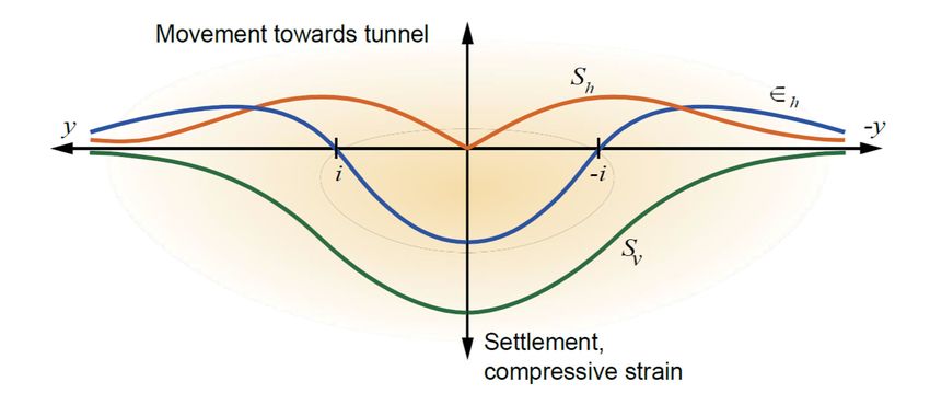
Bakerloo line extension - Information for Developers BUE4100-TFL-MAC-B001-REP-ZZ-00001
2.2 Horizontal movements

 Figure 2: Surface movement above a tunnel

 Building damage can also result from horizontal tensile strains, and therefore a
 prediction of horizontal movement is required. There are few case histories where
 horizontal movements have been measured, but the data that exist show reasonable
 agreement with the assumption of O’Reilly and New (1982) that the resultant vectors
 of ground movement are directed towards the tunnel axis. As shown on Figure 2
 above, the vector of ground movement has vertical and horizontal components and
 respectively. Assuming that the vector is directed towards the tunnel axis, then:

 which allows a simple assessment of horizontal movement. Equation 6 can be
 rewritten as:

 exp
 √2 2

 Horizontal strain can be determined by differentiating Equation 7 with respect to ,
 which gives:

 ∈ exp 1
 √2 2

 Page 21 of 42
Bakerloo line extension - Information for Developers BUE4100-TFL-MAC-B001-REP-ZZ-00001
 i.e.

 ∈ 1 1

 it is relevant to note that the vertical strain is given by:

 ∈ exp 1
 √2 2

 i.e.

 ∈ 1 ∈

 Since ∈ ∈ 0 a constant volume (i.e. undrained) condition is implied, which is
 generally found during tunnel construction in clay. For tunnels in sands or gravels,
 some bulking (dilation) of the ground might be expected, and Equations 6 to 8 are
 likely to over predict horizontal movements and strains.

 Figure 3 below shows the relation between the vertical settlement trough, the
 horizontal movements and horizontal strains occurring at ground level.

 In the region, , horizontal strains are compressive. At the points of inflexion
 , the horizontal movements are the greatest, and the horizontal strain is zero.
 For , the horizontal strains are tensile.

 Figure 3: Distribution of vertical and horizontal movements and horizontal strains above a tunnel

 Page 22 of 42
Bakerloo line extension - Information for Developers BUE4100-TFL-MAC-B001-REP-ZZ-00001
2.3 Multiple tunnels

 It is assumed that superposition can be applied using all the above equations. It is
 usually simplest to calculate movements and strains relative to a fixed reference point
 at the ground surface, and often the edge of a building is chosen.

 Such a case is illustrated on Figure 4 below.

 Figure 4: Cross section showing typical geometry with twin tunnels passing beneath a building

 For Tunnel 1, Equations 1 to 9 can all be used as required by substituting and
 in the equations. Similarly, for Tunnel 2, and should be
 substituted. Total movements and strains are then found by summation, for example:

 i.e.

 1

 exp exp
 √2 2 2

 Different tunnel diameters or volume loss parameters can be easily taken into account.

 Page 23 of 42
Bakerloo line extension - Information for Developers BUE4100-TFL-MAC-B001-REP-ZZ-00001
 The points of inflexion of the combined settlement trough are required for the
 assessment of building damage. For the settlement trough above a single tunnel, the
 slope is given by:

 exp
 √2 2

 and the curvature is given by

 exp 1
 √2 2

 The curvature of the settlement profile due to multiple tunnels can be determined by
 summation of the curvatures due to individual tunnels (a change in the sign of
 curvature occurs at a point of inflexion).

 Alternative methods of calculating ground movements due to tunnel excavation such
 as New and Bowers (1994) may be appropriate particularly for cases where structures
 are within one diameter of any tunnel.

 Page 24 of 42
Bakerloo line extension - Information for Developers BUE4100-TFL-MAC-B001-REP-ZZ-00001

 Building Strains
3.1 Relevant building dimensions

 It is necessary to define the relevant height and length of the building. A typical
 situation that might exist is shown on Figure 5. The height is taken as the height from
 foundation level to the eaves. It is assumed that a building can be considered
 separately either side of a point of inflexion, i.e. points of inflexion of the surface
 settlement profile will be used to divide the building. For example, building lengths
 and should be used respectively when assessing building damage in the hogging
 and sagging zones. The length of building will not be considered beyond the limit of
 the settlement trough, taken as, 2.5 , i.e. where ⁄ 0.044. In any calculation of
 building strain, the building span length is required and is defined as the length of
 building in a hogging or sagging zone (i.e. or as shown on Figure 5) and limited
 by a point of inflexion or extent of settlement trough as described.

 Figure 5: General case of a building affected by a tunnelling settlement trough

 Page 25 of 42
Bakerloo line extension - Information for Developers BUE4100-TFL-MAC-B001-REP-ZZ-00001
3.2 Strains due to ground settlement

 Ground movements will usually generate tensile strains in building which can lead to
 cracking and general damage. The problem of settlement damage to buildings was
 considered at length by Burland and Wroth (1974). They treated a building as an
 idealised beam with span and height deforming under a central point load to give
 a maximum deflection ∆. They argued that, for the portion of the building in the hogging
 mode, the restraining effect of the foundations would, in effect, lower the neutral axis
 which could therefore be taken to coincide with the lower extreme fibre of the ‘beam’.
 For the portion of the building in the sagging mode, however, it is reasonable to
 assume that the neutral axis remains in the middle of the ‘beam’. Burland and Wroth
 showed that these selections of the positions of the neutral axis are consistent with
 observations of building performance. Expressions were derived relating the ratio ∆⁄
 for the beam to the maximum relative bending strain (∈ ) and diagonal strain (∈ ). The
 strains in a building with a maximum relative settlement ∆ can also be determined from
 these expressions which were presented in a generalised form by Burland et al (1977)
 as:
 ∆ 3
 ∈
 12 2

 and

 ∆
 1 ∈
 18

 where is the height of the building,

 is the length of the building (but limited by any point of inflexion
 or extent of settlement trough as discussed above,

 and are respectively the Youngs modulus and shear modulus of the
 building (assumed to be acting as a beam),

 is the second moment of area of the equivalent beam (i.e.
 ⁄12 in the sagging zone and ⁄3 in the hogging zone), and

 is the furthest distance from the neutral axis to the edge
 of the beam (i.e. ⁄2 in the sagging zone and in the
 hogging zone).
 The maximum bending strain ∈ and diagonal strain ∈ are likely to develop at the
 centre and quarter span points respectively. Although masonry is not an isotropic
 material, the ratio ⁄ is often taken as 2.6, which is consistent with an isotropic
 Poisson’s ratio of 0.3, and this value is recommended.

 Figure 5 shows a general case of a building affected by a tunnel settlement trough. It
 is assumed that the building follows the ground settlement trough at the foundation
 level. The point of inflexion of the settlement trough (defined by for the case of a
 single tunnel) divides the building into two zones. In the hogging zone ( ), where
 the neutral axis is at the bottom, all strains due to bending will be tensile.
 Page 26 of 42
Bakerloo line extension - Information for Developers BUE4100-TFL-MAC-B001-REP-ZZ-00001
 In the sagging zone, where the neutral axis is at the centre of the building, bending
 will cause both compressive and tensile strains. Within each zone, the maximum ratio
 ∆⁄ can be determined, i.e. ∆ ⁄ in the hogging zone and ∆ ⁄ in the sagging zone,
 as shown on Figure 6. For a given ratio ∆⁄ , the hogging mode is likely to be more
 damaging than the sagging mode. This procedure essentially allows the building to be
 treated separately either side of the point of inflexion which is considered a reasonable
 approach. The maximum values of ∆ or ∆ are unlikely to occur at the centre of their
 respective span and in general it will be simplest to search for these numerically. It
 should be noted that this approach differs slightly from that suggested by Boscardin
 and Cording (1989) in which ∆⁄ was related to an angular distortion.

 Figure 6: Determination of maximum relative settlement ratio Δ/L

 In cases where the building span being considered has dimensions such that ,
 an additional ratio ∆ ⁄ should also be determined by considering smaller sub-
 spans of length within the overall span and the associated ∆ calculated
 using the procedure outlined above. For a particular building span, the maximum ratio
 of ∆⁄ determined using either the full building span length or should then be
 used in Equations 13 and 14.

 Page 27 of 42
Bakerloo line extension - Information for Developers BUE4100-TFL-MAC-B001-REP-ZZ-00001
3.3 Superposition of horizontal ground strain

 The horizontal ground strains due to bored tunnel construction will also contribute to
 building damage. The horizontal strains can be added directly to the bending strains
 giving:

 ∈ ∈ ∈

 where ∈ is the building strain.

 In assessing building damage, the maximum tensile strain is required, and this will
 generally be in the hogging zone where both ∈ and ∈ are tensile.

 Figure 7: Mohr's circle of strain used to determine ϵdt

 Diagonal (shear) strains and horizontal strains can be summoned by making use of
 Mohr’s circle of strain as shown on Figure 7. If a tensile horizontal strain, ∈ , is induced
 in the building, then in the vertical direction a compressive strain of -0.3∈ will result
 (assuming a Poisson’s ratio of 0.3). Two points on the Mohr’s circle are then (∈ , ∈ )
 and (-0.3∈ , ∈ and the circle can be constructed as shown. The maximum tensile
 strain due to diagonal distortion, ∈ is then given by:

 ∈ 0.35 ∈ 0.65 ∈ ∈ .

 A question arises when determining the appropriate value of ∈ . The recommended
 approach is to use Equations 5 and 6 to calculate the horizontal movement at either
 end of a building span under consideration and the difference between these divided

 Page 28 of 42
Bakerloo line extension - Information for Developers BUE4100-TFL-MAC-B001-REP-ZZ-00001
 by the span length then gives an average horizontal strain. If a sub-span gives the
 maximum ∆⁄ ratio, the average horizontal strain should be calculated for the
 particular sub-span used. Calculation of local horizontal strain using Equation 8 is
 considered unduly conservative and is not recommended.

 Page 29 of 42
Bakerloo line extension - Information for Developers BUE4100-TFL-MAC-B001-REP-ZZ-00001

 Assessment of Damage
4.1 Damage to buildings by settlement will be classified into various categories of risk as
 given in Burland et al (1977) and in the Building Research Establishment Digest 251:
 negligible, very slight, slight, moderate, severe and very severe. These categories,
 together with typical repairs that might be required for masonry buildings, are
 described in Table 1, Boscardin and Cording (1989) showed that these categories of
 damage are related to the magnitude of the maximum tensile strain induced in the
 structure, as shown in Table 1.

4.2 References

 Boscardin, M.D. and Cording, E.J. (1989). Building response to excavation induced
 settlement. Journal of Geotechnical Engineering, ASCE, Vol. 115, No 1, pp 1-21.

 Building Research Establishment Digest 251. Assessment of damage in low-rise
 buildings with particular reference to progressive foundation movement.

 Burland, J.B., Broms, B.B. and de Mello, V.F.B. (1977). Behaviour of foundations and
 structures. State-of-the-art report, Session 2, Proc. 9th Int. Conf. on Soil Mechanics
 and Foundation Engineering, Tokyo. Vol. 3, pp 495-546.

 Burland, J.B. and Wroth, C.P. (1974). Settlement of buildings and associated damage.
 Proc. Conference on Settlement of Structures, Cambridge. Pentech Press, pp 611-
 654.

 New, B.M. and O’Reilly, M.P. (1991). Tunnelling induced ground movements:
 predicting their magnitude and effect. 4th Int. Conf. on Ground Movements and
 Structures. Cardiff.

 O’Reilly, M.P. and New, B.M. (1982). Settlements above tunnels in the United
 Kingdom – their magnitude and prediction. Tunnelling ’82. Ed Jones, M.J. pp 173-181.
 London, IMM.

 New, B.M. and Bowers, K.H. Ground movement model validation at the HEATHROW
 EXPRESS TRIAL TUNNEL – Tunnelling ’94. pp 301-329. IMM. London.

 Page 30 of 42
Bakerloo line extension - Information for Developers BUE4100-TFL-MAC-B001-REP-ZZ-00001

Degree of Description of typical damage Approximate Limiting
 (ease of repair is in bold text) crack width tensile strain
 Hairline cracks of less than about < 0.1 0.0-0.05
0 Negligible 0.1mm are classed as negligible.
 Fine cracks which can easily be 1 0.05-0.075
1 Very slight treated during normal decoration.
 Perhaps isolated slight fracture in
 building. Cracks in external brickwork
 visible on close inspection.
 Cracks easily filled. Re-decoration 5 0.075-0.15
2 Slight probably required. Several slight
 fractures showing inside building.
 Cracks are visible externally and some
 repointing may be required externally
 to ensure weathertightness. Doors and
 windows may stick slightly.
 The cracks require some opening up 5 to 15 or a 0.15-0.3
3 Moderate and can be patched by a mason. Re- number of cracks
 current cracks can be masked by >3
 suitable linings. Repointing of
 external brickwork and possibly a
 small amount of brickwork to be
 replaced. Doors and windows sticking.
 Service pipes may fracture.
 Weathertightness often impaired.
 Extensive repair work involving 15 to 25 but also > 0.3
4 Severe breaking-out and replacing sections depends on
 of walls, especially over doors and number of cracks
 windows. Windows and door frames
 distorted, floor sloping noticeably. Walls
 leaning or bulging noticeably, some loss
 of bearing in beams. Service pipes
 disrupted.
 This requires a major repair job usually > 25 but
5 Very Severe involving partial or complete depends on
 rebuilding. Beams lose bearing, walls number of cracks
 lean badly and require shoring.
 Windows broken with distortion. Danger
 of instability.
* In assessing the degree of damage, account must be taken of its location in the building or structure.
** Crack width is only one aspect of damage and should not be used on its own as a direct measure of it.

 Table 1: Classification of visible damage to walls with particular refernce to ease of repair of plaster and brickwork or
 masonry (after Burland, Broms and de Mello, 1977: Boscardin and Cording, 1989)

 Page 31 of 42
Bakerloo line extension - Information for Developers BUE4100-TFL-MAC-B001-REP-ZZ-00001

 Summary of Calculation Procedure and Building
 Assessment
5.1 For each tunnel likely to affect a building, determine the depth from the cross section.
 Choose relevant values for and and determine (Equation 3) and (Equation 4)
 for each tunnel. Also calculate (Equation 2) for each tunnel.

5.2 Determine points of inflexion of the settlement profile beneath the building. This may
 involve the calculation of curvature where there are multiple tunnels (Equation 12).
 Hence define relevant building span lengths which will be limited by the extent of the
 building, the practical limit of the settlement trough and points of inflexion as
 appropriate.

5.3 Calculate values of (Equation 5) and (Equation 6) at the ends of the building
 span lengths.

5.4 Use the change in over the span length to determine the average horizontal strain,
 ∈ .

5.5 For each building span, calculate the average horizontal strain and the maximum ratio.
 NB an additional search for maximum ∆⁄ ratio is to be undertaken for sub-spans
 when exceeds , and if this value of ∆⁄ is used, the average horizontal strain
 should be recalculated for the relevant sub-span.

5.6 Calculate values for ∈ (Equation 13) and ∈ (Equation 14) and combine these to
 determine the maximum combined strains ∈ (Equation 15) and ∈ (Equation 16).
 Classify the building damage based on the maximum tensile strain according to Table
 1.

 Page 32 of 42
Bakerloo line extension - Information for Developers BUE4100-TFL-MAC-B001-REP-ZZ-00001

Appendix B
Noise and Vibration Assessment Summary

 Page 33 of 42
Bakerloo line extension - Information for Developers BUE4100-TFL-MAC-B001-REP-ZZ-00001

Crossrail 2

Noise and Vibration Assessment and Mitigation

Report No MTEW/1i3
Resiliently Supported Track
Tunnel Vibration Predictions

August 2016

 Crossrail 2
 Noise and Vibration Assessment and Mitigation

 Report No MTEW/1
 Tunnel Vibration Predictions

 Issue and Revised Record

 Issue Date Originator Checked Approved Description Status

 2 09/02/2016 RMTT FLT RMTT Report 2nd Issue

 3 08/08/2016 RMTT FLT RMTT Report 3rd Issue

Rupert Taylor Ltd
Consultants in Acoustics
Noise and Vibration,
Saxtead Hall,
Saxtead,
Woodbridge,
Suffolk.
IP13 9QT
Telephone: 01728 727424

rmtt@ruperttaylor.com

 Page 34 of 42
Bakerloo line extension - Information for Developers BUE4100-TFL-MAC-B001-REP-ZZ-00001

 Introduction
1.1 This report provides predictions of the vibrations of the wall of the tunnels in the
 Crossrail 2 central section, for use in the assessment of groundborne noise in adjacent
 buildings.

 Description of the Model
2.1 The prediction model used for these predictions employs an algorithm for the solution
 of the wave equation for the propagation of waves in bars, plates and solids, using
 finite difference methods. The model computes vibration of each element as a function
 of time, which is then subjected to Discrete Fourier Transform using a standard Fast
 Fourier Transform algorithm. The bandwidth of the prediction results covers the 1/3
 octave bands centred on 10Hz to 250Hz.

2.2 The model consists of a section of tunnel the length of one complete train consisting
 of nine vehicles, connected end-to-end to create an infinitely long tunnel and train. In
 view of the fact that the length of a Crossrail 2 train is many times the tunnel diameter,
 the modelling of an infinitely long train is valid. The tunnel is modelled as a tube
 surrounded by soil. Each rail is modelled as a beam supported on periodic resilient
 supports. The train is represented by the unsprung masses of the wheels and
 associated equipment, the sprung bogie masses, the secondary suspension and the
 car body.

 Assumptions
3.1 Track

 The track was modelled as the system installed on Crossrail 1, Sateba S312S3.

3.2 Vehicles

 The vehicles were modelled as Bombardier Class 345 using data as at December
 2014.

3.3 Tunnel Design

 The tunnel assumption was a 6.4m inside diameter tunnel with 400mm thick concrete
 linings.

3.4 Rail Roughness

 A roughness spectrum of 30dB re 1 micron in the 1/3 octave band centred on a
 wavelength of 2m, sloping at a rate of -15dB per decade to 0dB in the 1/3 octave band
 centred on 0.02m, This spectrum was used to represent the combined effects of wheel
 and rail roughness.

3.5 Soil

 The soil characteristics used were those of London Clay. The compression wave
 speed assumed was cs=1610 m/s and the loss factor η =0.1.
 Page 35 of 42
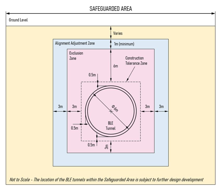
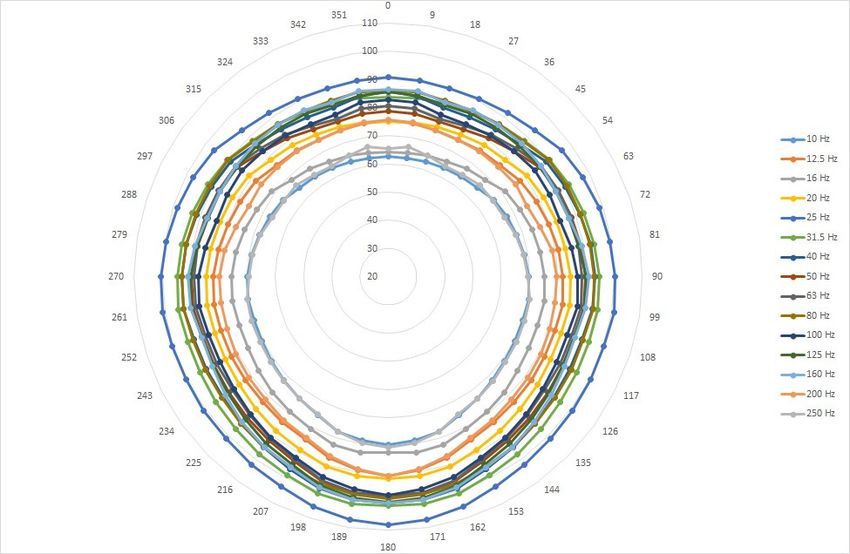
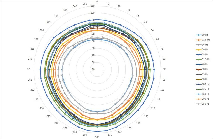
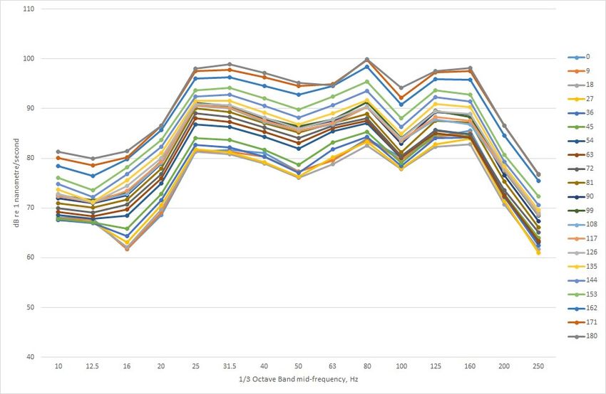
Bakerloo line extension - Information for Developers BUE4100-TFL-MAC-B001-REP-ZZ-00001

 Prediction Results
4.1 The results are presented in tabular form in Table 1 and Table 2 for two train speeds
 of 80km/h and 100km/h respectively, in terms of 1/3 octave spectra of radial tunnel
 wall velocity in decibels re 1 nanometre per second, for 40 positions around the tunnel
 circumference. The same data are also plotted in Figure 1, Figure 2, Figure 3 and
 Figure 4.

 Application of the Results
5.1 The results may be used for estimating the likely level of groundborne noise inside
 buildings above the tunnel alignment. For this purpose, it is necessary to take account
 of the effect of vibration propagation through the soil, of coupling loos factor between
 the soil and the building, and the dynamic response of the building. After applying
 corrections for these effects, the results in terms of the root-mean-square (rms)
 velocity in 1/3 octave bands can be used to estimate the sound pressure level inside
 a typical room. In many cases, the relationship between room sounds pressure level
 and ‘rms’ velocity of the room surfaces is approximately equivalent to 27 ,
 where is the 1/3 octave band sound pressure level: is the ‘rms’ vibration velocity
 in dB re 1 nanometre per second1.

5.2 Propagation through the soil is a very complex phenomenon, since the vibration is
 propagated in three way – as shear, compression and surface waves, and as shown
 by the results given in this report, the source strength varies around the tunnel
 circumference. A worst-case approach would be to take the highest levels in the tunnel
 wall ‘visible’ to the receiving structure, and use a distance function as follows:

 4.34 10 log

 Where is the tunnel wall radial velocity for a tunnel of radius and is the soil
 velocity at distance , both in dB re 1 nanometre/second, , is the phase speed of
 compression waves in soil with loss factor and is the angular frequency of each
 1/3 octave band in radians per second2. The coupling loss factor and building
 response generally have opposite sign and as a first order approximation they may be
 assumed to cancel. In the case of piled foundations, if is taken to be the shortest
 distance to any part of the nearest pile, a worst-case estimate will be obtained. Any
 distance units may be used, provided they are consistent throughout.

5.3 The overall 1/3 octave spectrum may be converted to dB(A) by decibel addition of the
 band levels after applying the value of the ‘A-weighting’ curve of each band centre
 frequency.

1
 Thornely-Taylor R. The relationship between floor vibration from an underground source and the airborne
sound pressure level in the room. International Journal of Rail Transportation 4(4), 2016, pp.247-255

2
 ISO/TS 14837-32:2015 Mechanical vibration – Ground-borne noise and vibration arising from rail systems
– Part 32: Measurement of dynamic properties of the ground
 Page 36 of 42
Bakerloo line extension - Information for Developers BUE4100-TFL-MAC-B001-REP-ZZ-00001
5.4 To obtain a more precise prediction of groundborne noise levels in buildings, it is
 necessary to use numerical modelling methods based on finite-difference or finite-
 element techniques.

 Page 37 of 42
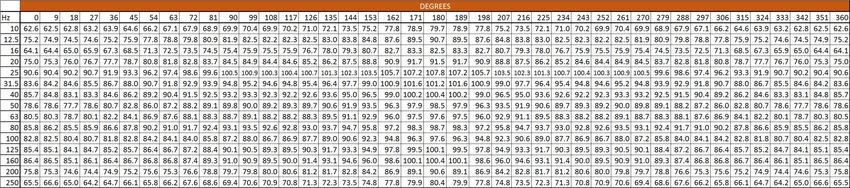
Bakerloo line extension - Information for Developers BUE4100-TFL-MAC-B001-REP-ZZ-00001

 Table 1: 1/3 Octave band spectra of vibration velocity of tunnel circumference (0 degree = crown), dB re 1 nanometre per second. Train speed: 80km/h

 Table 2: 1/3 Octave band spectra of vibration velocity of tunnel circumference (0 degree = crown), dB re 1 nanometre per second. Train speed: 100km/h

 Page 38 of 42
Bakerloo line extension - Information for Developers BUE4100-TFL-MAC-B001-REP-ZZ-00001

 Figure 1: Distribution of vibration levels around tunnel circumference (0 degree - crown) 80km/h

 Page 39 of 42
Bakerloo line extension - Information for Developers BUE4100-TFL-MAC-B001-REP-ZZ-00001

 Figure 2: Distribution of vibration levels around tunnel circumference (0 degrees - crown) 100 km/h dB re 1 nm/s

 Page 40 of 42
Bakerloo line extension - Information for Developers BUE4100-TFL-MAC-B001-REP-ZZ-00001

 Figure 3: Distribution of vibration levels around tunnel circumference - 80 km/h dB re 1 nm/s

 Page 41 of 42
Bakerloo line extension - Information for Developers BUE4100-TFL-MAC-B001-REP-ZZ-00001

 Figure 4: Distribution of vibration levels around tunnel circumference - 100 km/h dB re 1 nm/s

 Page 42 of 42
You can also read