Biomethane - Energetische Biomassenutzung
←
→
Page content transcription
If your browser does not render page correctly, please read the page content below

FOCUS ON

Biomethane
Biomass for Energy

FOKUSHEFT

Biomethan
Energetische Biomassenutzung

www.energetische-biomassenutzung.de   1/2012
View
                      Editorial                                                              3
                      Ways of biomethane-production                                          4
                      Technological approaches for the provision of methane from biomass

        Researched
                      Biomethane derived from agriculture                                    9
                      Upgrading of Biomethane in Grabsleben/Thuringia

                      Get the sulphur out!                                                  14
                      Regenerable filters made of metal alloy foam facilitate
                      biogas desulphurization

                      Biomethane directly out of the gasifier?                              16
                      Demonstration of decentralised production of Bio-SNG

                      From chip oil to fuel                                                 18
                      The greasoline process

                      Faster and cleaner                                                    20
                      Hohenheim university researches new biogas technology

            Traded
                      Biomethane trading                                                    21
                      Germany, Sweden, the Netherlands, Switzerland and
                      Austria lead the way in Europe

                      On the path to ecogas                                                  24
                      The customers of Lichtblick AG are creating a large
                      demand in the consumer segment

                      „Far and away the most climate-friendly mobilty…“                     25
                      Interview with Dr Oliver Lüdtke (Verbio AG)

                      Gas mobilises                                                         27
                      100% biomethane at the fuel dispenser

                      Sustainability – a top priority!                                      29
                      Bioenergy park „Güstrow“ certified to new criteria

                      The climate balance of biomethane                                     32

         DiscusSed
                      Incentives for biomethane use                                         35
                      What do policy makers for the expansion of biomethane use?

                      „Biomethane can become the system service provider...“            38
                      Interview whith Prof Frank Scholwin (DBFZ)

                      Calculate your feed-in tariff!                                        40

                      Demand-responsive energy supply from biomethane                        41
                      Yes to energy change! But does it have to be a biogas plant?          42
                      Interview with Dr Sabine Strauch (Fraunhofer UMSICHT)

   Country profiles
                      Long term potentials in Eastern Europe                                45
                      Case study for the Russian Federation, Ukraine and Belarus

                      Boosting the European market for biogas production,
                      upgrade and feed-in into the natural gas grid                         47
                      The GreenGasGrids project

                      Germany                                                               49
                      Austria                                                               51
                      Poland                                                                53
                      Great Britain                                                         54
                      Finland                                                               55
                      Sweden                                                                56
                      The Netherlands                                                       57
                      Switzerland                                                           58

Further Information
                      Further informations on biomethane                                    59
FOCUS ON

Biomethane
Biomass for Energy

  Biomethane
  Biomethane is defined as methane, which is produced from
  biogenic resources by technical processes. Biomethane can be
  generated by bio-chemical conversion (via biogas) or thermo-
  chemical conversion (via Bio-SNG). By certain upgrading measu-
  res the gas composition and especially the methane content is
  upgraded to natural gas quality. Alternatively bio natural gas is
  used as term for biomethane.

Editorial
Dear Readers,

Renewable energy is one of the mainstays of a sustainable      Apart from sustainable development of domestic sources,
energy supply in Germany. Through a targeted subsidies         particular attention should also be paid to cross-border
policy and accompanying growth, many positive effects          trading with biomethane. Although very good potential for
have already been achieved. Apart from a significant re-       Europe-wide trading already exists due to the available
duction in greenhouse gas emissions, numerous of invest-       pipe network, there are considerable hurdles in the way
ments have been made in plants and production capacities       of transnational injection and output of biomethane: Gas
and therefore a large number of jobs have been created.        network access and rights of use, gas qualities, traceability
The bioenergy industry has already achieved considerable       from the producer through to the end user and establishing
economic success. The transfer of innovative technologies      sustainable markets are only a few of the obstacles to be
has also resulted in the starting up of numerous interna-      overcome. While trading with solid and liquid biogenic fuels
tional cooperations.                                           is currently being established, biomethane trading is still in
                                                               the initial stage; nonetheless, a reliable base of scientific
To make the environmental and energy policy a success          studies, the first promising examples and transferable ex-
story in the 21st century too, it is not only necessary to     perience already exist.
achieve progress in energy efficiency and lowering power
consumption but also to match the individual renewable         The articles in this brochure are exemplary focused on
energy sources to each other in line with demand. In par-      these issues and describe country profiles, innovative ap-
ticular, bioenergy must be used when and where other           proaches and the expectations of the producers and pur-
alternatives are not available. Biomethane, which is fed       chasers of trading with biomethane. Only through interdis-
into the natural gas network, offers enormous potential for    ciplinary and international exchange and by highlighting
use here, not only for combined heat and power produc-         functioning examples is it possible to examine their trans-
tion (CHP) but also in the fuel sector. The first plants for   ferability and to develop biomethane trading.
biomethane production and injection have now been in op-
eration in Germany for six years.                              Enjoy reading!

                                                                                            Prof Daniela Thrän
                                                                                            Head of department
                                                                                            Bioenergy Systems, DBFZ

                                                                                                                                3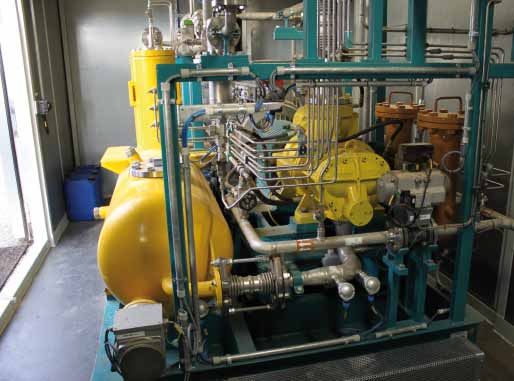
Ways of
    biomethane
    production
    Technological approaches
    for the provision of methane
    from biomass
                                                                                                Johan Grope, Stefan Rönsch, Michael Seiffert

    The utilisation of natural gas within the European energy system is    been used in commercial projects in many European countries.
    of high importance. Intensive activities concerning the substitution   Methane, or in this context biomethane, has a high market poten-
    of natural gas with so called biomethane or synthetic natural gas      tial as a well-known energy carrier (transport sector, stationary ap-
    (Bio-SNG) are currently ongoing, in order to meet the governments      plications (heat and power)) and for material utilisation too. Within
    objectives in the context of climate protection and diversification    the existing and well developed natural gas grid in Europe biometh-
    of energy sources. A number of concepts are available such as,         ane can easily be fed in and distributed to the final consumer in
    the production of biomethane from the bio-chemical conversion of       industry and households.
    biomass (biogas) and via thermo-chemical conversion of solid bio-      Beside the above mentioned advantages, the combustion proper-
    mass, so called Bio-SNG. Technologies for the feed-in, distribution,   ties of methane are already well known and characterised through
    as well as utilisation of biomethane are mature and have already       comparably low emissions.

    Figure 1: Value chain of biomethane production and use

4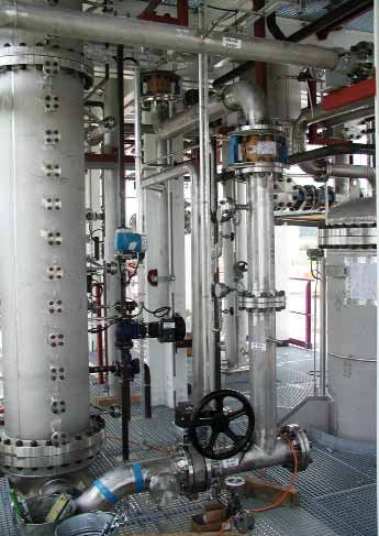
Basics of biomethane provision                                          Biogas pathway
Due to the aspects of climate protection and availability numerous      The bio-chemical conversion pathway of biomass to biomethane
political decisions like the EU implementation of the Kyoto-proto-      can be subdivided into two main process steps: (i) the biogas pro-
col, the EU wide CO2-control for passenger cars and light duty vehi-    duction based on anaerobic digestion or rather wet fermentation
cles, the exhaust standards for passenger cars and duty vehicles        of biomass residues (and organic wastes) as well as energy crops
(reduction of particles and NOx-emissions) or the diversification of    (e.g. maize silage) and (ii) the upgrading of biogas or rather raw-
fuel mix – the energy carrier natural gas and therefore biomethane      biogas to biomethane.
gained importance. Biomethane can be added to natural gas and           The production of biogas has a long history and has become a
allows therefore an increase of domestic resources as well as an        market mature technology for the provision of electrical and/or
improvement of confidence in terms of a secure gas provision.           thermal energy in conversion units with capacities ranging from
Besides numerous technical benefits, like the possibility to store      a few kWCH4 up to 10 MWCH4. For a long time it was common prac-
biomethane and provide demand oriented and flexible energy, bi-         tice to provide energy only directly from biogas without any or just
omethane can contribute significantly as a „green“ and environ-         a crude purification. For making the advantages of biomethane,
mentally sound energy carrier to fulfill the greenhouse gas reduc-      which were mentioned above, more accessible, the upgrading of
tion goals. Biomethane can be a market opener for increasing gas        raw-biogas to biomethane has become a more prominent alter-
sales within the transportation sector, because of its low environ-     native to the utilization of the biogas on-site. In many European
mental impact in comparison to other fuels. Additionally, biometh-      countries projects using biogas-upgrading plants have been estab-
ane can also be used with high conversion efficiency within the         lished and these upgrading technologies have been shown to be
heat and the electricity market.                                        suitable for daily use, even though there is still a high potential
The bio- and thermo-chemical conversion routes allow both the           for optimizing the existing biogas upgrading plants and developing
provision of biomethane for the subsequent feed-in or application       new biogas upgrading technologies. In the following sections, the
within the mobile and stationary sector. Nevertheless, numerous         two main process steps involved in the bio-chemical conversion
aspects distinguish the pathways significantly.                         of biomethane production will be described with a focus on the
For the production of biogas mainly substrates like excrements          second step, the upgrading of biogas to biomethane:
from animal husbandry, energy crops or organic residues (e. g.
household; industry) are used. Against this background the raw          Raw-biogas production
material supply chain can be based from a local up to a regional
logistic concept. This has a significant impact on the plant capacity   Biogas can be produced out of any organic material under anaero-
which is in a typical range of a few MWCH4 for agricultural plants to   bic conditions. Microorganisms convert the biomass to biogas in
several 10 MWCH4 for conversion plants using industrial residues.       several sub-steps. Many settings, besides the anaerobic condi-
In comparison, the production of biomethane via gasification is         tions, like e. g. temperature between 37 and 42 °C (mesophilic
based on lignocellulose like woody biomass. Thus, logistical con-       conditions) or 50 to 60 °C (thermophilic conditions), the adequate
cepts can be applied that are already in use for the pulp and pa-       biomass mix or the provision of the microorganisms with nutrient
per, as well as wood processing industry, which are typically re-       matter influence the efficiency and the stability of the biogas pro-
gional up to transnational. Expected conversion plant capacities        duction process. There are many different processes within the di-
are in the range of several 10 MWCH4 up to a few 100 MWCH4 [1].         gester which can influence the efficiency and stability of the biogas
Thus, both concepts complete each other in terms of biomass as-         production process, for examplethe anaerobic conditions, like e. g.
sortments and logistical concepts.                                      temperatures between 37 and 42 °C (mesophilic conditions) or
In the following sections the main technical steps of the single        50 to 60 °C (thermophilic conditions), the adequate mixing of the
biomethane provision concepts based on biomass will be de-              biomass or the provision of adequate nutrients to the microorgan-
scribed briefly.                                                        isms. Primarily, depending on the feedstock, the composition of
                                                                        the biogas varies from 50 to 75 % methane (CH4) and 25 to 45 %
                                                                        carbon dioxide (CO2). Besides these main components, raw-biogas
                                                                        is saturated with water and contains different micronutrients; the
                                                                        most important is hydrogen-sulphide (H2S). [2]

                                                                        Upgrading of raw-biogas to biomethane
                                                                        Before biogas can be injected into the gas distribution system, it
                                                                        must be upgraded to gas with equivalent quality characteristics to
                                                                        natural gas, or so called “biomethane” gas. To achieve this, the
                                                                        CH4 content of the biogas must be increased, which is being done
                                                                        by removing most of the CO2 from the biogas. Furthermore the gas
                                                                        has to be dried to a certain water dew point, depending on the
                                                                        pressure of the gas grid, where the biomethane is supposed to be
                                                                        injected. Last but not least, different micronutrients – essentially
                                                                        the H2S – have to be removed from the rawbiogas. An exemplary il-
                                                                        lustration of the process steps of biogas upgrading to biomethane
                                                                        is shown in figure 2.
                                                                        The technologies for the removal of CO2 differ in the principle
                                                                        means of separation between CH4 and CO2, important operational
                                                                        parameters include, the necessity of a pre-purification (mainly re-
                                                                        moval of H2S), the required operation pressure, the heat demand
                                                                        or rather the temperature for the regeneration process, the meth-
                                                                        ane loss and the methane content of the product gas at normal
                                                                        process design (cf. tab. 1). Most technologies for upgrading biogas
                                                                        are based on well-established processes for upgrading natural gas
                                                                        or process gases of different origin [3]. Upgrading technologies,
                                                                        which are mainly used for the treatment of biogas, will be shortly
                                                                        described in the following.

                                                                                                                                                5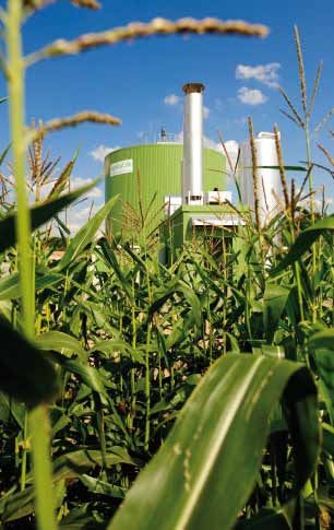
Figure 2: Process steps for upgrading biogas to biomethane (see [3] Graf, Bajohr, et al.)

    Pressure Swing Adsorption (PSA)                                                   washing solution. The process can be implemented with atmos-
    The PSA refers to the fact that gas molecules’ adsorption abil-                   pheric pressure or only minimal pressure above, though it requires
    ity differs and highly depends on the partial pressure. In PSA CO2                a standard temperature for the regeneration of the loaded washing
    and remaining traces of other gases from raw biogas are removed                   solution between 100 and 180 °C.
    through adsorption onto an adsorbent (e. g. active carbon) at high
    pressure (4 to 10 bars). The adsorbent is being regenerated at low                Seperation by membranes
    pressure.                                                                         The separation of CO2 and CH4 by membranes is based on a se-
    H2S and water vapour must be removed from the raw biogas before                   lective permeation of the membrane. The process only works
    coming in contact with the adsorbent, since these substances can                  with a pressure difference between the up- and the downstream
    damage the active carbon required in the process.                                 of the membranes. Operational pressures in common technolo-
                                                                                      gies vary between 6 and 10 bars. As high permeation results in
    Pressurized water scrubbing (PWS)                                                 low selectivity between CO2 and CH4, a compromise between high
    PWS is a physical absorption process and is based on the principle                methane losses and high methane content in the product gas has
    of different solubility of gases in washing solutions, depending on               to be found. The cleaning of the raw biogas before entering the
    pressure and temperature. In common technologies, the biogas is                   membranes is of high importance, as H2S, water and particles can
    separated into CH4 and CO2 in water-filled pressure columns (most-                cause damage of the membranes.
    ly at around 7 bars), where CO2 and other components like H2S are                 All upgrading-technologies cannot achieve a complete separation
    being absorbed by the water. By lowering the pressure and with the                of the CH4 and the CO2. This causes a loss of methane, leaving the
    help of stripping air jet of air to remove, the CO2 is desorbed after-            process with the lean gas or rather the CO2-stream. To avoid high
    wards which allows the water to be used in a closed loop. A drying                methane emissions, a treatment of the lean gas, e. g. by a catalytic
    of the biomethane afterwards is necessary.                                        or regenerative oxidation, can be necessary.

    Genosorb                                                                          Bio-SNG Pathway
    Like PWS, this biogas upgrading process is based on a physical
    absorption.                                                                       The conversion of biomass into Bio-SNG is not as far developed as
    Unlike to the PWS a washing solution that is highly absorptive of                 the biomethane production via biogas. Current biomass gasifica-
    CO2 and H2S is involved. The washing solution Genosorb is regener-                tion based on water vapour (as gasification medium) for the pro-
    ate at high-temperatures up to 80 °C.                                             duction of heat and electricity is successfully demonstrated and
                                                                                      mature. The required subsequent methanation was realised in a
    Amine washing                                                                     demonstration stage with a MW thermal capacity so far [4]. The
    The cleaning of biogas using amines (e. g. monoethanolamine)                      Bio-SNG production is characterised by the possibility of using rela-
    is based on a chemical reaction between the CO2 and the amine                     tively small conversion units with capacities in a range of 10 up to

                                                     PSA                      PWS                Gensorb               Amine               Membrane

     pre-purification                                yes                    roughly               roughly                yes                  yes

     methane loss                                  2 – 10%                  1 – 2%                1 – 4%               < 0,1%               3 – 5%

     methane content in product gas                 > 96%                   > 97%                 > 97%                > 99%               96 – 98%

     operating pressure [bar]                       4 – 10                  4 – 10                 4–8                    –                  6–8

     heat demand [°C]                                 –                        –                 55 – 80             100 – 180                 –

    Table 1: Process parameters of different biogas upgrading technologies, source: DBFZ

6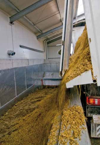
100 MWbf. Hence, the conversion of regionally available lignocel-         Gas cleaning
lulosic biomass is feasible.
The production of synthetic biofuel, electricity and heat (so called      Depending on the gasification parameters (e. g. reactor design,
tri-generation) allows high overall efficiencies (e. g. high CO2 miti-    gasification pressure, gasification temperature and gasification
gation potential) within the entire production process. As distin-        agent) the raw gas contains different impurities as particles (e.g.
guished from the production of BtL fuels (like Fischer-Tropsch-           char, dust, ash, bed material), tars (e. g. C7H8, C10H8), sulphur com-
fuels), the Bio-SNG production system is characterized by lower           pounds (e.g. H2S, COS, thiophenes), nitrogen compounds (e.g. NH3,
technical and financial risks due to a technology that is less com-       HCN), Halogens (e. g. HCl) and alkali compounds (e. g. Na- and
plex (e. g. raw product upgrading). Based on these circumstances a        K-compounds).
rapid and easy market entrance could be possible.                         To avoid catalyst poisoning in the subsequent synthesis (e. g.
The thermo chemical production pathway of synthetic natural gas           caused by organic sulphur) and damage of other plant compo-
aims to convert solid biofuels into gas with relatively high methane      nents (e. g. corrosion of heat-exchanger surfaces) the raw gas has
content (approx. 95 %). The conversions pathway from biomass              to be cleaned after leaving the gasifier. To remove the impurities
to Bio-SNG can be subdivided into five process steps: (i) biomass         mentioned above, various cleaning methods are available at the
pretreatment, (ii) biomass gasification, (iii) raw gas cleaning, (iv)     market.
methanation and (v) raw-SNG upgrading.
                                                                          Methanation
Biomass pre-treatment
                                                                          The process step methanation comprises of a catalyst-based syn-
Due to its heterogeneous characteristics biomass has to be pre-           thesis with the aim to increase the methane content of the cleaned
treated before gasification to ensure a reliable feeding into the         gas.
gasification reactor on the one hand and to allow optimal gasifica-       Thereby, the gas components hydrogen and carbon monoxide are
tion conditions inside the gasification reactor on the other hand.        converted to methane and water-steam (see equ. 1).
Thereby, in general, the pre-treatment focuses on an adaption of
the biomass size to meet the demands of the feeding system and
of the drying of the biomass to reduce the energetic losses of the
gasification process.
As entrained-flow gasifiers require a pumpable or dispersible fuel,
their application demands a special biomass pre-treatment (e. g.
pyrolysis, torrefaction). The biomass pre-treatment can be distin-
guished between mechanical, thermal and thermo-chemical pre-
treatment.
                                                                          CO         +          3 H2                   CH4      +       H2O
Biomass gasification                                                                                                                           Equ. 1

Gasification is a thermo-chemical conversion process, where the
gasification media (pretreated fuel) is converted into gaseous fuel       In principle, all metals of the 8th group catalyse the methane syn-
(called raw gas) with the main components CO2, CO, H2O, H2 and            thesis. However, due to their availability and price stability the use
depending on the gasification parameters certain amounts of CH4.          of nickel catalyst is of particular interest. The catalysts work in a
[5]                                                                       wide pressure (1 – 80 bar) and temperature range (250 – 650 °C),
As the process is basically endothermic, heat is needed for the           but, the desired formation of methane is enhanced at low tempera-
process. Beside the main gas components the raw gas contains              tures and high pressures. To ensure a high carbon monoxide con-
different impurities, such as particles, tars, sulphur compounds,         version, a H2/CO-ratio of at least 3/1 is advisable. However, as raw
nitrogen compounds, halogens and alkali compounds. The amount             gases from biomass gasification processes are typically character-
of impurities depends on multiple process conditions and can be           ised by H2/CO-ratios of 0.3 – 2.0, an adjustment of this ratio is gen-
influenced by gasification technology and conditions.                     erally foreseen either by adding additional hydrogen or by convert-
Gasification processes can be distinguished according to the (i)          ing carbon monoxide and water-steam into hydrogen and carbon
gasification agent, (ii) gasification pressure level, (iii) heat supply   dioxide according to the water gas shift reaction. As nickel catalysts
and (iv) the reactor design.                                              catalyse the water gas shift reaction well at elevated temperatures
                                                                          and pressures, the water gas shift reaction can be integrated in the
                                                                          methanation reactor instead of an upstream shift-reactor before
                                                                          the methanation.
                                                                          Basically, methanation reactors can be distinguished according to
                                                                          the fluid-dynamic behaviour of their catalysts in fixed-bed reactors
                                                                          and fluidised-bed reactors. [6]

                                                                                                                      CHP Güssing, photo: DBFZ

                                                                                                                                                        7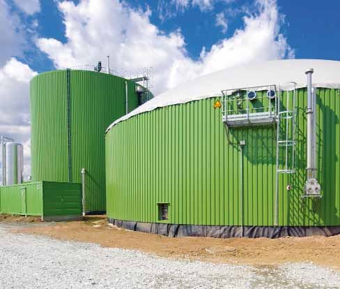
Raw-SNG upgrading
                                                                                             To feed Bio-SNG into the natural gas grid, it has to fulfill the quality
                                                                                             requirements of the grid. Therefore, a final raw-SNG upgrading step
                                                                                             after the methanation is necessary. The raw-SNG upgrading in-
                                                                                             cludes the separation of carbon dioxide, water and – depending on
                                                                                             the raw-SNG quality, other gas components (e. g. hydrogen). There-
                                                                                             fore, beside the Bio-SNG composition and purity, the Wobbe index
                                                                                             is of particular interest. For all raw-SNG upgrading steps several
                                                                                             technologies are currently available at the market and in operation
                                                                                             for coal gas treatment processes, natural gas treatment processes
                                                                                             and biogas upgrading processes. However, due to their different
                                                                                             technical and operational effort, selected technologies are advis-
                                                                                             able for small scale and others for large scale applications.
                                                                                             The production of SNG can occur so far within a very promising
                                                                                             concept via the steam gasification of woody biomass with water
                                                                                             as gasification agent, gas cleaning, subsequent methanation and
                                                                                             upgrading.
                                                                                             The steam gasification and the gas cleaning have been demon-
                                                                                             strated successfully in a full technical scale for instance at the bio-
                                                                                             mass combined heat and power (CHP) gasification plant in Güss-
                                                                                             ing/Austria.
                                                                                             In the following numerous gasification plants were established
                                                                                             (Austria: Oberwart, Villach; Germany: Ulm) or are currently within its
                                                                                             planning phase (Austria: Klagenfurt; Sweden: Gothenburg).
                                                                                             Generally, steam gasification leads to a producer gas with a rela-
                                                                                             tively high content of hydrogen and methane as well as a low con-
                                                                                             tent of nitrogen. These properties are necessary for an efficient
                                                                                             SNG production. Within figure 3 an overview to the Bio-SNG produc-
                                                                        photo: REPOTEC
                                                                                             tion process is given.

    Figure 4: Process flow diagram (Bio-SNG)

    References
    [1] M. Kaltschmitt, H. Hofbauer, S. Stucki, M. Seiffert; Methane from wood – challenges and opportunities, Presentation at the energy convent, Stockholm, 2007
    [2] J. Friehe, P. Weiland, A. Schattauer; Grundlagen der anaeroben Fermentation, Leitfaden Biogas, Gülzow, 2010
    [3] F. Graf, S. Bajohr et al.; Biogas – Erzeugung, Aufbereitung, Einspeisung, München, 2011
    [4] Project description - Demonstration of the Production and Utilization of Synthetic Natural Gas (SNG) from Solid Biofuels, 2005
    [5] Knoef, HAM (2005) Handbook biomass gasification. 1st Ed., BTG biomass technology group BV, Enschede
    [6] Rönsch, S., Ortwein, A.: Methanisierung von Synthesegasen – Grundlagen und Verfahrensentwicklungen, Chemie Ingenieur Technik, Vol. 83 (2011), 1200-1208“

8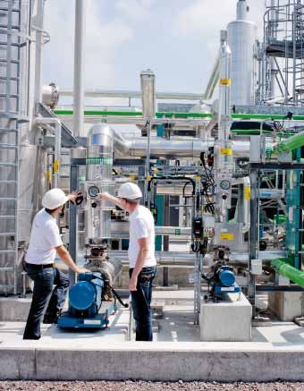
Biomethane derived
from agriculture
Upgrading of biomethane in Grabsleben/Thuringia
Heike Gröber, photos: DBFZ
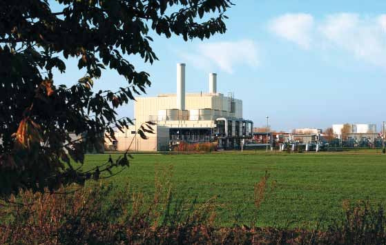
In the middle of Thuringia, in the Erfurt Basin, lies the picturesque village of
Grabsleben. In August 2010, a biomethane plant started up operation, which
since then has produced 50 million kWh energy a year. We follow the path from
the raw material through to the “natural gas fine” biomethane...
The six biogas towers on the edge of Grabsleben can be seen from
far away. They belong to GraNottGas GmbH and are in the immedi-
ate vicinity of the agricultural holding of the 450 resident communi-
ty. This supplies part of the raw materials, from which biomethane
is produced at the end of a long process chain.
Even the operator model keeps a firm eye on the stable raw ma-
terial supply. Apart from Landwirtschaftlichen Betrieb Grabsleben
GmbH & Co. KG., BBW Nottleben GbR is also a shareholder of
GraNottGas GmbH, and has operated the biogas site since 2010.
Both farms use around one quarter of their land for the cultiva-
tion of energy crops, which are located at a maximum distance of
twelve kilometres from the biogas plant. The fermenters are filled
daily with 90 t maize and 10 t rye-whole crop silage. Slurry from the
pig-fattening facility in Alkersleben is also added, and is delivered
at regular intervals.
Approx. 10 million euro has been invested in the Grabsleben site, to build
the biogas, the methane upgrading plant and the CHP. The entire plant
produces approx. 50 million kWh energy a year. The main customer for
the green biomethane is the Frankfurt airport. The heat produced on site
during power generation is almost completely used in the gas cleaning.
9
Materials used and feeding the biogas plant

                                                              Slurry delivery                                                Solids input by means of containers

     Slurry is regularly delivered for operation of the biogas plant. It contains 80 % pig slurry and 20 % cattle slurry. The renewable raw
     materials used consists of 90 t maize silage and 10 t rye-whole plant silage per day (which are delivered by the farms involved).

                                                                                     alised material cycle. The Franconian biogas pioneer Balling coolly
                                                                                     waved aside the complaint of the rampant maize cultivation: “Here
                                                                                     in Thuringia we mainly have a cereal monoculture. Therefore, the
                                                                                     maize we grow tends to facilitate crop rotation rather than domi-
                                                                                     nate it.”
                                                                                     Up to 56,000 t of silage can be stored in GraNottGas GmbH’s four
                                                                                     large silos, which in total would secure plant operation for one and
                                                                                     a half years.
                                                           Thomas Balling,
                                                           managing director
                                                           of the biogas plant       Two fermenters in use
                                                           in Grabsleben
                                                                                     Once a day, Daniel Zapfe climbs into his multi-handler, in fact a
                                                                                     construction vehicle, whose driver’s cab can be extended to 4 m
     “We achieve an energy yield of 85 % with biogas”, explained Tho-                height and whose bucket reaches deep into the silage. When he
     mas Balling, one of the managing directors of the plant in Grabsle-             tips out his load, 2.5 t of fresh nutrients are emptied into an open
     ben and at the same time, shareholder of the Nottlebener farm.                  container, from which the bacteria in the warm fermenter obtain
     “Three quarters of the materials used is output again at the end of             their fresh supplies.
     the biogas processes as fermentation residue and contain all the                The biogas plant has two fermenters, which are connected in paral-
     constituents of high-quality fertiliser”, he says, describing the ide-          lel. In front of these are so-called solid feed containers with pusher

10
To ensure that the maximum concentration of hydrogen sulphide used for the combustion of biogas in the CHP biological desulphurisation takes place in
the secondary fermenter. In the process an atmospheric oxygen is added and the hydrogen sulphide is converted into elemental sulphur and water.
plates, by means of which the ferment is automatically loaded. The
integrated scale exactly records the quantities added. Before they
are added to the fermenter, solid (NawaRo) and liquid substrate
are mixed together. This process, called liquid feeding, reduces the
stirring required in the fermenter and ensures a homogeneous dis-
tribution of the substrates to be fed in.
In the fermenter, in an atmosphere without air, bacteria process
the starting material, such as proteins, carbohydrates and greases,
in several steps to produce biogas, which mainly consists of meth-
ane and carbon dioxide. The fermentation takes place within the
mesophile range at a constant temperature of 40-42 °C and a pH
value within the neutral range (6.7- 7.5 pH). The biogas is collected
by means of a gastight sheeting and is temporarily stored. The coni-
cally shaped weatherproofing sheeting is kept in shape by a fan.
After the appropriate dwell time in the fermenter, the fermentation
substrate is moved to the gas-tight secondary fermenter for further
outgassing. The end station for the fermentation products until
they are applied to the farmland is one of the three fermentation The heart of the CHP plant, a room with a twelve-cylinder internal-
residue stores. combustion engine, can only be entered with ear protectors,
because of the deafeningly loud noise of the 1.000 HP machine.
11Plant manager Daniel Zapfe
in one of the 14.000 t silos
Combined heat and power
Of the 50 million kWh produced in the biogas plant, around 20 mil-
lion kWh are generated through the heat and power of a CHP and
condensing boiler.
The CHP used is a Jenbacher (gas-fired combustion engine) with an
output of 650 kWhel. The exhaust gas is passed through an after-
burning process to satisfy the requirements for the formaldehyde
bonus.
The heat simultaneously produced by CHP is required to heat the
fermenter and for regeneration of the scrubbing solution from the
gas upgrading. The residual heat is currently removed, but in future
An ultrasonic meter determines the officially it is planned to use it to heat the office building still under construc-
accepted quantity of gas tion and the rooms of the Grabsleben farm.
A conventional biogas plant ends at the CHP, not so in Grabsleben,
where the gas’s path is continued, up to the injection point of the
gas grid.
Part of the amine scrubbing facility
Washed, dried & compressed
The raw biogas leaves the plant with approx 52 percent methane.
The rest is mainly CO2 and is separated out in the subsequent
cleaning process.
The gas is upgraded using the pressureless amine scrubbing proc-
ess of MT-Biomethan GmbH. Before the actual scrubbing process,
interferents such as water and hydrogen sulphide must be removed
from the raw biogas. Apart from removing the condensate, fine
desulphurisation takes place with the help of an activated carbon
filter, before the dried and cooled gas in the scrubbing plant. 700
Nm3 raw biogas is upgraded to 350 Nm3 biomethane in an hour in
Grabsleben and it is fed into the network of the natural gas supply
company Thüringen-Sachsen mbH (utility company).
The black giant
The highest structure of the methanation unit is a black cylinder. It
is where the pressureless amine scrubbing takes place. With the
help of this process it is possible to separate out the unwanted car-
bon dioxide from the welcome methane and therefore to increase
the calorific value of the biogas so far that it is hardly any different
from its fossil brother natural gas.
The dehumidified and desulphurised biogas flows from below into
the scrubbing column. An aqueous amine solution is injected into
the contraflow to the biogas. Packing in the scrubbing column
increases the surface area of the scrubbing solution, so that in-
tensive substance exchange can take place between the gas and
liquid phase. Due to their chemical properties, the amine solution
can readily absorb the carbon dioxide contained in the biogas. The
methane, on the other hand, does not react with the scrubbing liq-
uid and is drawn off as highly pure biomethane at the top of the
column. The selectivity of the scrubbing solution leads to minimum
methane losses of < 0.1 %, also called methane slip.
12Screw compressor Reciprocating compressor
If the biomethane in the start-up process still does not have the
required quality, it is burned off as “bad gas” via the emergency
gas flare.
After it has been cleaned the biomethane must be cooled and
dried again. To do this, it is passed through a heat exchanger. There
the water and amine vapour still contained in the gas condenses
on the cooling surfaces before it is returned to the scrubbing cycle.
To regenerate the scrubbing solution, the carbon dioxide is driven
out by adding heat and is discharged in the atmosphere. The scrub-
bing solution can then be used again.
“With the use of heat exchangers to cool the biomethane and
the use of the waste heat from the biogas CHP to regenerate the
scrubbing solution, the energy is efficiently used in the pressure-
less amine scrubbing process”, explains Volkmar Braune, who as Compressor container
a plant technician of Erdgasversorgungsgesellschaft Thüringen-
Sachsen mbH (EVG), is responsible for proper operation of the
feed-in plant.
Measured & injected
Before it is fed into the natural gas network, the quality and quantity
of the biomethane produced is determined. The gas flows through
complicated pipes with different sensors which, among other
things, monitor the moisture or dust content. A gas chromatograph
provides information about the gas quality. The official measure-
ment to determine the quantity of biomethane, used as the basis
of the gas billing, is carried out using an ultrasonic gas meter. Fur-
ther, the biomethane must be compressed from 300 mbar to 25
bar for injection into the long-distance transport pipeline network
of the utility company. Either a screw compressor or as a substitute
a reciprocating compressor is used.
It arrives relatively unspectacularly - the point at which the biometh-
ane leaves the biogas plant including upgrading and flows into the
natural gas network. It is only a single pipe between the building
wall and floor and yet means that the environment is spared 5,000
tonnes CO2.
Quite unspectacular: The entry point of the methane upgrading
plant into the gas grid of the natural gas supply company
„Erdgasversorgungsgesellschaft Thüringen-Sachsen“ (EVG)
13Get the sulphur out!
Regenerable filters made of metal alloy foam
facilitate biogas desulphurization
René Poss, photos: Alantum GmbH, Fraunhofer IKTS
Desulphurisation of biogas is prerequisite for its efficient use. Alantum Europe
GmbH together with its partners develops new solutions, which offer economic
and ecological advantages for the upgrading of the renewable energy source
and for the after-treatment of exhaust gases containing sulphur. This is based
on porous metal foam, which is tailored to the applications.
Desulphurisation with metal foam Environmentally friendly fine desulphurisation with
up to 50 % cost savings
Apart from the actual energy source methane, biogas produced
during the microbiological degradation of organic matter also con- Fine desulphurisation is used to upgrade biogas to natural gas
tains, among other things, hydrogen sulphide. As this fraction has quality. At present, this is primarily done using activated carbon
corrosive properties and is environmentally harmful, it is usually fil- with potassium iodide. However, it is then necessary to dispose
tered out before the biogas is used to generate electrical power, for of the sulphur-saturated substrates. On the one hand, this has a
running vehicles or is fed into gas supply networks. If biogas is used negative effect on the environmental friendliness of the process
in combined heat and power stations without fine desulphurisa- and on the other, it is expensive.
tion of the biogas beforehand, a robust, sulphur-resistant oxidation
catalyst is required for the aftertreatment of the exhaust gases. In a project sponsored by the German Federal Ministry of the En-
The porous metal alloy foam of Alantum Europe GmbH can be used vironment, Alantum Europe GmbH together with the Fraunhofer
to implement innovative systems for both applications. Institutes for Ceramic Technologies and Systems (Institut für Kera-
mische Technologien und Systeme – IKTS) and Manufacturing
Technology and Advanced Materials (“Institut für Fertigungstech-
nik und Angewandte Materialforschung” – IFAM), and Lehmann
Maschinenbau GmbH, is working on a regenerable filter system.
The substrate used is porous metal alloy foam, which – like the
Biogas can be desulfurized with the help of metal foam not only
environmentally friendly but also up to 50 % cheaper.
14The laboratory test bench for the process of testing the
coated metal-foam-substrate for desulfurization of biogas
at the Fraunhofer-Institute IKTS.
previous used wood chippings and pellets – is coated with iron
oxide. Due to the higher loads with the sorbent, the metal foam
based filters can be designed to be smaller and yet have the same
Who is Alantum?
cleaning efficiency. In addition, due to the larger surface area com- Founded in 2006, Alantum Europe GmbH is a subsidiary of the Ko-
pared to wood pellets, the operating period before regeneration is rean Alantum Corporation, which in turn is a subsidiary belonging
expected to be up to 4 times longer, as the loading with elemen- to the Korea Zinc and Korea Nickel Corporation.
tary sulphur takes a longer time. The elementary sulphur left on Alantum’s key expertise includes the research and development
the foam surface by the regeneration reduces the active surface
and manufacture and sale of iron and nickel-based metal and
area. The required purity is no longer guaranteed above a critical
metal alloy foams.
sulphur load and the filter element must be replaced. In this case,
the technologies used to date (activated carbon, zinc oxide and
Alantum’s metal alloy foams are used in applications such as
wood pellets) only provide for disposal of the filter elements on the after-treatment of car and truck exhausts, as well as rail
land fill sites. The aim is to remove this disadvantage using tech- and off-road vehicles and stationary diesel engines. An SCR sys-
nology with which the sulphur is removed from the foam surface, tem (selective catalytic reduction) is currently being developed.
either thermally or chemically, without having a negative effect on Catalytically coated, alloyed metal foam is used as the primary
the filter system (in particular, causing deactivation of the sorb- product for this. Due to its properties, the metal alloy foam is also
ent or permanent damage to the foam). The removed sulphur is particularly interesting for use chemical plant construction for
collected and, for example, is returned to the economic cycle as heterogeneous catalysis processes. On the one hand, this is be-
fertiliser. After use, the filter does not have to be disposed of on a cause of its large reactive surface area and on the other hand its
landfill site, but instead its components are returned to the materi- uniform and completely porous structure. Possible uses include
al cycle using existing recycling concepts (e.g. melting them down). reformer technologies such as hydrogen production. Other areas
These advantages reduce the costs per kilogram of sulphur re-
in which the alloy foams are used include filter systems, silencers,
moved from 16 to 20 euros to date to around 10 euros. This defi-
heat exchangers, spark separation and flame distribution as well
nitely contributes to reducing the price of biogas, until now rela-
tively high compared to natural gas.
as biogas desulphurisation.
Large-volume production and research laboratory
Alantum currently produces around four million square metres
of nickel foam per year in China. It also produces 500.000 m3 of
metal alloy foam in Korea. The Munich-based company is working
closely with the Fraunhofer IFAM in Dresden to further optimise the
material for biogas desulphurisation applications. The IFAM has its
own research laboratory in which tests can be performed and sam-
ples produced.
A project the BMU-funding-programme
Partners: Alantum Europe GmbH
Due to its porous structure the metal sulfide binds
Fraunhofer IKTS
more foam than other conventional solutions. Here‘s
Fraunhofer IFAM
the foam loaded to its half. photos: Alantum
15The allotherm gasifier called
HPR®500 operates on the principle
of a heat pipe reformer.
Biomethane directly
out of the gasifier?
Demonstration of decentralised
production of Bio-SNG in the heat pipe reformer
Sebastian Fendt
Use of biomass as an energy source frequently reaches its limits conditions for injection into the grid are defined in the DVGW stand-
based on the conversion chains used to date. The causes are mani- ards G 260, 262 and 280-1. In general, this gas is called synthetic
fold and diverse. On the one hand the resources are limited and natural gas (Bio-SNG).
on the other hand in many cases the energy yield leaves much to
be desired. Rising biomass prices and inadequate energy recovery Use decoupled from the production
frequently lead to economic difficulties for the plant operators. In
new plants, for example combined heat and power or district heat- The main advantages of Bio-SNG are its low-emissions production,
ing plants, the focus is not only on economic aspects but also the the ability to store energy in the large gas stores available and its
sustainability of the use change and local emissions. use, decoupled from the production and its locations, in efficient
Producing a gaseous energy source is an additional option to con- CHPs, fuel cells and gas and steam plants. A decisive factor for its
ventional use chains via the direct burning of biomass and conver- use in cogeneration (combined heat and power) plants is that this
sion into heat and electricity. Here the biomass is first converted takes place in locations with a high heat requirement. However, the
into a gas mixture consisting of CO, H2, CH4, CO2 and H2O by means exothermic reaction during the methanation also produces heat for
of thermo-chemical gasification. The gas mixture also contains con- heating purposes at the production site.
taminants and interferents such as dust particles, tar, sulphur and Biomass-based gasification and methanation plants can be built
chlorine compounds. These are largely removed in the gas clean- within the output range up to around 100 MW power. Limiting fac-
ing, consisting of particle filter, tar reduction and sulphur adsorp- tors are the availability of the biomasses, the transport logistics
tion. and ability of the natural gas grid to accept the gas during low-
consumption periods (summer). Decentralised (local) production
Methanation of SNG within the small output range of around 500 kW up to sev-
eral MW has several advantages: In particular, these include good
Any carbon monoxide (CO) and carbon dioxide (CO2) can be exo- availability of the biomass, the chance of building a plant (permit,
thermally converted to methane (CH4) using a catalytic process. acceptance) and efficient heat use.
This reaction stage is called methanation or methanation. The However, the pressure of costs is increasing substantially, especial-
most reaction equation for this is: ly for decentralised plants. Therefore, the most simple processes
possible and cost-effective biomasses are required.
CO + 3 H2 CH4 + H2O With good framework conditions, around 65 % of the energy con-
tained in the biomass can be converted into SNG and 25 to 30 %
By separating out CO2 and water vapour, a synthetic energy source into heat. In this way, in total, 80 to 90 % of the biomass can be
can be provided, equivalent to natural gas (figure 1). This gaseous used for energy purposes and the greenhouse emissions are re-
energy source produced from biomass can be fed into existing nat- duced by more than 85 % compared to fossil natural gas. An im-
ural gas pipes at the appropriate pressures. Relevant framework portant factor is the substantially lower emissions (e. g. fine dust
Bio-SNG
biomass gas cleaning Conditioning
gasification tars, methanation CO2 and
S-, N-, Cl-components water removal
Q (heat)
Figure 1: Process chain for the supply of synthetic natural gas (Bio-SNG), source: TUM.
16Figure 2: The HPR®500 heat pipe reformer coupled with the SNG process. photos: Sebastian Fendt
produced during combustion of the gas) compared to e.g. chip-
pings or pellets.
The objective of the “Local production of Synthetic Natural Gas
(Bio-SNG) from the product gas of an allothermal biomass gasi-
fier” project (ID: 03KB042) is to develop a decentralised Bio-SNG
process and to demonstrate the process in conjunction with the
so-called heat pipe reformer HPR®500 (figure 2). This is an allo-
thermal gasifier made by h s energieanlagen gmbh with an output
of 500 kW. The gasifier is commercially available and is currently
used for combined heat and power generation with microgas tur-
bines. Figure 4: In-situ filter with integrated catalyst.
Cleaning Laboratory facilities for examining the gas cleaning and methana-
tion are set up on the basis of simulations. This is done using a test
As methanation is a highly exothermic and catalytic process, trace plant in which the various reactors and the different catalysts and
elements such as tars, alkalis, chlorine and sulphur as well as the adsorbents are tested (figure 3). The aim is to reduce the tars pro-
heat management in the reactor are particularly important. The duced during gasification – as far as possible – in the gasifier with
trace substances can influence the function and activity of the cat- the help of catalytic in-situ tar conversion (figure 4).
alysts. An important part of the investigations is therefore cleaning
the gas mixture to remove contaminants. The subsequent exother- Test of the adsorbents
mic methanation takes place in a fixed-bed reactor.
In this way, within the scope of the project, the necessary basic
principles are drawn up for the development of a competitive proc-
ess. The plan is to use a larger number of SNG plants, which are
comparatively small compared to other developments, in conjunc-
tion with the HPR®500.
Further information is available under:
http://www.energetische-biomassenutzung.de/de/vorhaben/liste-
aller-vorhaben/details/projects/85.html
A project the BMU-funding-programme
Partners: Technical University of Munich (TUM), Institute of Energy
Systems, h s energieanlagen gmbh
Figure 3: Laboratory system for gas cleaning and methanation.
17From chip oil to fuel
The Greasoline process shows a way
to multiple biomass use
Dr Thomas Isenburg
The market place for innovation and trends in the automobile in- als. The market potential lies in the same application areas as the
dustry, the international motor show (“Internationale Automobile comparable fossil products. The hydrocarbon mixture should have
Ausstellung” - IAA), took place in Frankfurt am Main at the begin- the same hydrocarbon fractions, consisting of methane, ethane,
ning of September 2011. Leading representatives of the vehicle propane and butane, as in natural gas. This new biogas is then
manufacturers and energy industry, as well as automobile custom- directly suitable for use as a fuel in the commercially available com-
ers agreed to increase the use of natural gas and biomethane as bustion engines.
transport fuels and therefore to contribute to the reduction of CO2
emissions in road traffic. Stephan Kohler, chairman of the manag- Catalytic cracking
ing board of Deutsche Energie-Agentur GmbH (dena) said: “Togeth-
er, we want to tap the large potential of natural gas and biometh- One research subject is therefore the catalytic cracking of vege-
ane as climate-friendly fuels. table oil and grease residues to produce high-quality, linear and
Within the scope of the Kyoto protocol, the EU has pledged that oxygen-free hydrocarbons with C1 to C4 carbon chains. The basic
by 2012 it will reduce greenhouse gas (GHG) emissions by 8 % of processing principle has been known of since the start of the 20th
the 1990 GHG reference value and to make traffic in Europe more century, but is only now being technical implemented.
sustainable. At the EU conference in 2007 it was proposed that by To this end, the biogenic greases and oils are converted into hydro-
2020, 10 % of the fuels used in the transport sector in each mem- carbons on catalysts at temperatures between 400°C and 500°C.
ber state must be covered by bio fuels. In most cases processes involve the use zeolithic silicon/alumini-
um based catalysts and vegetable oils such as rapeseed or palm
High quality hydrocarbons oil or also waste cooking fats.
Under the aspect of raw material shortages, the use of waste fats As part of the “Energetic biomass use” programme funded by
to produce biogenic fuels is also a much-discussed topic. After the BMU, the researchers of the Fraunhofer UMSICHT are devel-
deacidification, high-quality waste fats (used frying oils, UFO) from oping the process further in the project: “Screening of bio-based
system catering companies could be used to produce biodiesel. In wastes concerning their applicability to conversion into petrol and
this field of research, the Fraunhofer Institute for Environmental, diesel fuel fractions by catalytic cracking” (ID: 03KB007). Biofuel
Safety and Energy Technology (UMSICHT) in Oberhausen has been researcher Dr Volker Heil of the research institute presented the
supplying promising research results for a significantly long time. In laboratory and pilot plant for the gasoline process during a visit and
the “greasoline” process, grease is used to produce diesel fuel and explained the patented inventions: “Biogenic oils and greases are
petrol (“gasoline”). A further planned approach is to convert the evaporated and together with a carrier gas, and if applicable steam
“used or spent” biogenic greases in high-quality gaseous hydrocar- at 350 to 500 °C are passed without pressure through an acti-
bons for natural gas substitution.
The process is intended to produce the hydrocarbons methane,
ethane, propane and butane from waste greases of biogenic origin.
The biomethane, called ‘bio-natural gas’ exclusively consists of the
hydrocarbon methane. Until now it has been produced from farm
manure (slurry) and biowastes. One vision is to blend this biometh-
ane, which is solely made up of methane, with the higher-quality
hydrocarbons ethane, propane and butane from the greasoline Triclycerides are acyl-acid
process, so that it can be injected into the gas grid as a natural residues that are esterified
gas substitute (Bio-SNG). The propane and butane fractions can with glycerol. The residues R
be used as car gas (LPG) to drive motor vehicles. Another alterna- represent hydrocarbon-chains
tive is to produce ethylene and propylene as chemical raw materi- consisting mostly of various fatty acids.
18vated carbon catalyst”. The starting material used in the tests was are condensed. The liquid product is then collected and is analysed
waste cooking oil, which was primarily made up of rapeseed oil and by means of gas chromatography in combination with mass spec-
palm oil. Vegetable oils such as rapeseed, soya, palm or sunflower trometry. Higher catalyst temperatures and longer grease dwell
oil belong to the group of substances called lipids. These are made times on the activate carbon surface result in short-chain hydrocar-
up of a mixture of different triglycerides. These primarily consist of bons that are gaseous at room temperature.
a glycerine molecule whose OH groups have been esterified with These can be used to produce high-calorie fuel gases as the main
aliphatic carboxylic acids (fatty acids). components. By adjusting the process parameters, up to 53 % of
The product at the end of the process is made up of pure hydrocar- the energy yield can be achieved from gas. Alkenes are increas-
bons. The oxygen from the acid and ester groups is discharged as ingly produced on inorganic catalysts and alkanes are primarily pro-
CO and CO2. The hydrocarbons produced in this way are therefore duced by carbon-based catalysts.In determining the suitable test
oxygen free, this is a large advantage compared to the methods parameters, the mixture of product gases with a carbon number of
known to date for the production of biodiesel, in which fatty acids C1 – C4 can be adjusted so that it can be optimally used for further
containing oxygen are produced by base-catalysed ester hydrolysis use as a natural gas substitute or liquid gas fuel.
(saponification). The oxygen can then cause corrosion processes The scientists in Oberhausen have a laboratory and pilot plant that
in the engine. One objective of the tests is also to determine the can be used for this. Until now, 60 g hydrocarbon per hour can be
optimum process parameters for the production of short-chain hy- converted in the laboratory plant. The pilot plant processes 3 kg
drocarbon blends as natural gas substitutes for running combus- waste grease per hour.
tion engines.
Capture the market
The greasoline process
In 2003/2004, world production of biogenic greases and oils was
In its basic form, the greasoline process is a three-stage process approximately 126 million tonnes. Around 20 % of these greases
chain consisting of feedstock evaporation, catalytic reaction and and oils are used as feed and as raw material for the oleochemical
cooling. industry. Around 80 % of the greases and oils are used as food,
First, following mechanical precleaning, the grease is liquefied at where a large proportion of the greases are used in catering and
temperature of around 70°C, to make it pumpable and to pump privately for frying, especially deep-fat frying. These greases are
it into a second preheating stage where the hydrocarbon mixture merged by so-called waste grease collectors and are re-processed.
is heated to at least 180 °C. It is then passed into an evaporator. In Germany, approximately 300.000 tonnes per year are collected
There it is converted into the gas phase at 450°C and is combined from the catering industry. The Oberhausen scientists have start-
with water vapour and nitrogen preheated to approx. 300°C. The ed up a company, in which the researchers are shareholders, to
mixture of substances then flows into a fixed-bed reactor filled with market and industrially implement their biorefinery concept. The
activated carbon. Various reactions take place in which, at 400°C patented concept uses the biomass twice. The spent greases are
– 500°C, the triglycerides are catalytically converted on the acti- also to be used as a natural gas substitute. The process will now be
vated carbon into a mixture of different hydrocarbons. The resulting placed on the market with the help of economic experts. Mineral oil
products are then cooled in the next process step and, if possible, companies are possible addressees.
Schemata of the greasoline process
(source: Fraunhofer UMSICHT) A project the BMU-funding-programme
Partner: Fraunhofer UMSICHT
19Faster and cleaner
Pilot plant should produce the purest
methane possible using faster method
Franziska Schories
A new test plant at the University of Hohenheim should make it As this process technically simplifies the gas upgrading consider-
possible to upgrade biogas to natural gas quality with less energy ably and increases energy efficiency, a significant cost reduction
input, and to then inject it into the natural gas grid. The objective could be achieved. The hope is that in future it will be possible to
of the joint research project of the University of Hohenheim and make biomethane production economically feasible even in small
the DVGW research unit of the Karlsruhe Institute of Technology plants.
(Karlsruher Institut für Technologie - KIT) is to develop a new type
of plant, which combines the advantages of flexible substrate use, Constant pressure
a shorter process time and a methane content of over 85 percent
in the end product. The particular challenge for the scientists at present is to keep the
pressure in the fermenter constant, because a sudden pressure
Combine seperate processes drop, e.g. when the gas is removed, would cause the bacteria to
break up. For this reason, the control engineering must be per-
To date, biomethane has mainly been produced in large plants, in fected before the plant is put into service, so that the fermentation
which the biogas produced is cleaned to remove water, hydrogen can take place fully automatically, and without pressure changes.
sulphide and carbon dioxide and is then compressed in a sepa- The project is being sponsored by the German Federal Ministry of
rate process requiring high energy input. In most of the treatment Research until April 2013.
processes raw biogas is compressed to 10 bar. In the small pilot
plant in Hohenheim, this process is now to be carried out by spe- Further information:
cial methane gas bacteria during the fermentation process. In the www.uni-hohenheim.de
Hohenheim plant, the gas production of the bacterial builds up and State Institute of Agricultural Engineering and Bioenergy
maintains a controlled overpressure. The emerging biogas is there-
fore already pressurised with an increased process pressure. At the
same time, the gas is cleaned during its production: “This means
that the pressure and purity are ensured during the fermentation
of the biomass and do not have to be produced in technically elabo-
rate downstream processes”, explained the agronomist Dr Andreas
Lemmer, who is leading the research project at the University of
Hohenheim.
Two-phase anaerobic digestion
The innovative approach of the Hohenheim project lies in the two-
phase fermentation, in which the fermenting and the methanogen-
esis processes are separated. This accelerates the overall process:
For example, while it takes at least 70 to 100 days to decompose
grass in a single-phase plant, it will only require around 18 to 25
days in the new plant. The low pH values and high temperatures in
the first phase means that difficult to decompose substrates can
also be broken down and therefore the range of materials used
can be extended.
20You can also read