Buckling stability analysis of underpinning piles during basement excavation beneath existing buildings
←
→
Page content transcription
If your browser does not render page correctly, please read the page content below
www.nature.com/scientificreports
OPEN Buckling stability analysis
of underpinning piles
during basement excavation
beneath existing buildings
Huafeng Shan1*, Jie Yang2, Zhiwen Hu3 & Shaoheng He4
In the present paper, the pile-soil system’s total potential energy equation of underpinning piles
was established based on the Winkler elastic foundation beam theory. This energy equation was
used to explore the effect of basement excavation beneath existing buildings on the underpinning
pile’ buckling stability. Utilizing the minimum potential energy theory, the expression of the
critical buckling load for underpinning piles’ stability during the excavation project was obtained.
Moreover, the influencing factors of the critical buckling load were investigated. It was found that
the underpinning pile’s critical load converged with the augment of half-wave number. Moreover, the
pile skin friction and deadweight had an insignificant influence on it. In addition, the critical load of
underpinning piles decreased sharply with the increasing excavation depth and gradually increased
with the augment of pile diameter. The results of this study provides a basis for the design of adding
piles in similar projects and reduces the hidden danger of excavation instability.
The technology of basement excavation beneath existing buildings is to underpin the foundation for existing
buildings without damaging the superstructure, and then the earthwork is excavated to the design depth and the
basement foundation slab is poured to add a basement. This technology has attracted extensive attention locally
and globally because it can not only solve the problem of insufficient underground space for the old buildings
downtown, giving these buildings a “second life”, but also avoid the economic loss caused by the demolition and
reconstruction.
At present, some scholars have done considerable research on this issue. Iwasaki et al.1 introduced a new
subway tunnel project of an underground shopping mall in Nagoya, Japan. Jia et al.2 using the finite element
method, simulated the working conditions of basement excavation beneath a three-storey frame structure. Gong
et al.3 researched the lateral friction mechanism of existing piles during basement excavation beneath existing
buildings. Wu et al.4,5 devised an approach to explain the mechanism of pile end resistance and analyzed the
impact of excavation construction on the existing piles’ bearing stiffness. Shan et al.6 extended this method to
pile group foundations of existing buildings and studied the impact of excavation on settlement characteristics
of existing pile group foundations. Note that all the above analyses focus on the impact of basement excavation
beneath existing buildings on the bearing capacity and settlement of the original foundation piles. Wang et al7–9
studied the deformation and internal force of pile.
As for the buckling stability of pile foundations, early studies illustrate that buckling instability will not occur
when piles of the ordinary size are pressed into soft soil. However, with long piles and super-long piles, buckling
problems of foundation piles will a rise10. For instance, Reddy et al.11 experimentally studied the buckling insta-
bility phenomenon of foundation piles through laboratory tests. Lee et al.12 put forward an energy approach for
calculating the buckling and instability of foundation piles. Using the Ritz method, Zhu13 obtained the calculation
length for stability of bridge pile foundations. Zhao14,15 proposed different buckling load calculation expressions
under different constraint conditions of foundation piles. Zou et al.16, using the energy method, studied the
buckling stability of rock-socketed piles with a highrise pile cap under the complex subgrade reaction modulus.
However, the effect of excavation on the foundation piles’ stability has not been studied yet. During basement
excavation beneath existing buildings, with the increasing excavation depth, the soil layer constraint around the
1
School of Civil Engineering and Architecture, Taizhou University, Taizhou 318000, China. 2Zhejiang Fangyuan
New Materials Co., Ltd., Taizhou 318000, Zhejiang, China. 3Taizhou Huangyan Municipal Garden Construction
and Development Co., LTD., Taizhou 318000, Zhejiang, China. 4Research Center of Costal and Urban Geotechnical
Engineering, Zhejiang University, Hangzhou 310058, Zhejiang, China. *email: shanhf@zju.edu.cn
Scientific Reports | (2022) 12:8138 | https://doi.org/10.1038/s41598-022-11791-8 1
Vol.:(0123456789)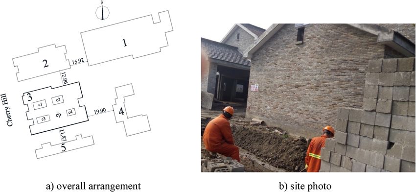
www.nature.com/scientificreports/

                                                  Figure 1.  Overall arrangement and site photo of the Ganshuixiang project (unit: m). 1–5 denote No. 1–5
                                                  section of Ganshuixiang; c1-4 denote No. 1–4 courtyard; cp is soil sampling point;

                                            Layer thickness     Soil unit weight                    Internal friction   Compression                       Friction
           Layer no   Name                  (m)                 (kN/m3)            Cohesion (kPa)   angle (°)           modulus (MPa)   Poisson’s ratio   eigenvalue (kPa)
           1          Miscellaneous fill    0.9                 –                  –                –                   –               –                 –
           2          Silty clay            0.6                 18.70              8.9              3.6                 3.5             0.35              –
           3          Clay silt             6.1                 18.55              12.1             27.4                10.5            0.35              20
           4          Sludge                3.8                 16.15              8.5              2.9                 2.5             0.35              7
           5          Gravelly silty clay   1.9                 19.00              40.0             13.8                6.0             0.35              25
                      Fully weathered
           6                                2.5                 19.77                                                   15.0            0.35
                      sandstone
                      Highly weathered
           7                                2.2                 19.77              146.3            20.5                25.0            0.25              55
                      sandstone
                      Moderately weath-
           8                                –                   –                  –                –                   > 50.0          0.25              75
                      ered sandstone

                                                  Table 1.  Physico-chemical properties of soils.

                                                  pile on the foundation pile gradually disappears, resulting in the increase of the foundation pile’s free length,
                                                  which is likely to cause buckling and instability of foundation piles under the pile top load. Therefore, it is
                                                  necessary to study the influence of excavation on the foundation pile’s buckling stability. Herein, based on the
                                                  basement construction project of Ganshuixiang in No. 3 section (hereafter called the Ganshuixiang project),
                                                  combined with the Winkler elastic foundation beam theory, the pile-soil system’s total potential energy equa-
                                                  tion was established. By using the minimum potential energy theory, the expression of the critical buckling load
                                                  and calculation length for underpinning piles’ stability was obtained. The influences of half-wave number, pile
                                                  deadweight, pile skin friction, pile diameter and excavation depth on the underpinning piles’ critical buckling
                                                  load were analyzed, which could provide a reference for relevant projects.

                                                  Project overview
                                                  The Ganshuixiang project lies in Ganshuixiang, Zhakou Street, Shangcheng District, which is a typical project
                                                  in Hangzhou, Zhejiang Province. This project is proximate to the White Pagoda Park. To keep harmony with the
                                                  environment of the scenic spot, this project adopts an antique building with a building height of 8.01 m. The main
                                                  body is a frame structure with two stories (partially one-story), and without basement. No. 2 section and No. 5
                                                  section of Ganshuixiang are located in the north and south of this project. The building in the east direction is
                                                  No. 4 section which is under construction, and Cherry Hill lies in the west. The detailed layout is displayed in
                                                  Fig. 1. The Ganshuixiang project is a case in typical soft soil. Its physico-chemical properties are given in Table 1.
                                                  As the superstructure load is tiny, an isolated foundation under the pillar with a 1.80-m buried depth is utilized.
                                                     After the completion of the project, the community owners discovered that the building lacked sufficient
                                                  usable area. To this end, they planned to add a basement beneath the existing building with an estimated exca-
                                                  vation depth of 4.42 m.

          Scientific Reports |      (2022) 12:8138 |                    https://doi.org/10.1038/s41598-022-11791-8                                                           2

Vol:.(1234567890)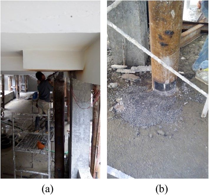
www.nature.com/scientificreports/
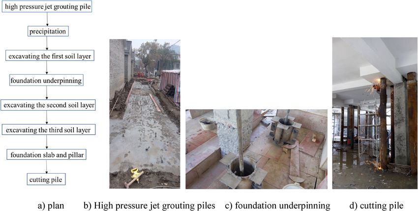
Figure 2. Construction flowchart of the Ganshuixiang project.
8.010
5.532
-1.800 -1.800
the first rowof
soil nail existing
foundation
high perssure jet
underpinning grouting pile
pile
dewatering well
Figure 3. Excavating the first soil layer and constructing underpinning piles (unit: m).
Construction technology of basement excavation
lans17. This section introduced the con-
Different superstructures and foundations need different excavation p
struction flow of the project, as illustrated in Fig. 2:
The detailed technology for construction is as follows:
1. High pressure jet grouting piles were built as the building envelope of the foundation pit, as shown in Fig. 2b.
2. The first soil layer had an excavation depth of 1.80 m, i.e., the buried depth of the isolated foundation. Then,
the first layer of the soil nailing wall was built, as given in Fig. 3.
3. The second soil layer had an excavation depth of 3.0 m. With the deeper excavation depth, the soil constraint
on the pile side gradually dropped. Subjected to the pile top’s axial load, the foundation pile might buckle and
become unstable. Therefore, when the excavation depth came up to 3.0 m, steel supports should be welded
between foundation piles, as presented in Fig. 3, to avoid buckling instability of these piles. Then, the second
layer of the soil nailing wall was built.
4. The third soil layer had an excavation depth of 4.42 m, and the third layer of the soil nailing wall was built.
5. Subsequently, the basement cushion as well as the foundation slab was poured. Then, the initial isolated
foundation and foundation beam were chiselled away. The new basement structural pillar was poured.
6. To improve the new basement’s space use rate, underpinning piles ought to be removed in this project, as
shown in Fig. 2d.
The Ganshuixiang project’s main structure was completed at this point.
Scientific Reports | (2022) 12:8138 | https://doi.org/10.1038/s41598-022-11791-8 3
Vol.:(0123456789)www.nature.com/scientificreports/
P
P
EHIRUHWKH
EDVHPHQW
H[FDYDWLRQ
l0
VRLO DIWHUWKH
l EDVHPHQW
H[FDYDWLRQ
h
x
y
Figure 4. Buckling analysis model.
Buckling stability equation
Buckling analysis. In practical engineering cases, it is difficult to achieve ideal consolidation between pile
and cap, and the pile top constraint is usually between fixed support and hinged support. Therefore, this paper
assumed that pile top constraint was elastic embedding. However, in this project, steel pipe piles were not rock-
socketed. They only stood on stable rock strata. Therefore, this paper assumed that the pile end constraint was
hinged support. Due to the complicated pile-pile and pile-soil interactions in pile group foundations, this paper
only analyzed the effect of excavation beneath existing buildings on the single pile foundation’s buckling instabil-
ity, and the excavation method of soil layer was considered as layered excavation. Its calculation model is shown
in Fig. 4.
The interaction between the soil layer around the pile and the pile was simulated by Winkler springs. There-
fore, the subgrade reaction q(x) could be obtained by the m method recommended by the specification18:
q(x) = kyb0 = m(h − x)yb0 (0 ≤ x ≤ h) (1)
where k is the subgrade reaction coefficient; b0 is the calculation width; m is the coefficient.
Since the horizontal load test of underpinning piles had not been carried out in this project, the following
empirical formula was adopted to calculate the m value18.
0.2ϕ 2 − ϕ + c
m= (2)
vb
where φ is soil layer’s friction angle; c is its cohesion; vb is the horizontal displacement value, taken as 10 mm in
the soft soil area19,20.
Since the site of this project was multi-layer soil rather than homogeneous soil layer, this paper took the
weighted average of soil layer thickness as suggested by Chen et al.21.
According to the existing test d ata22, the calculation width could be expressed as:
b0 = kf k0 kd (3)
where kf is the character conversion coefficient; k0 is the force conversion coefficient; k is the coefficient of mutual
influence between piles; d is the pile diameter.
The calculation of Eq. (3) is complex and its parameters are difficult to determine. Therefore, a simplified
calculation method is proposed in C hina20,22.
In terms of circular piles:
b0 = 0.9(1.5d + 0.5) d ≤ 1 m
b0 = 0.9(d + 1) d ≤ 1 m (4)
For rectangular piles:
b0 = 1.5d + 0.5 d ≤ 1m
b0 = d + 1 d > 1m (5)
Combined with the restraint conditions of pile top and pile end, according to the Ritz method, the buckling
deformation of the pile was as follows:
n
2i − 1
y= ci sin πx (6)
2l
i=1
where ci is the undetermined coefficient; l is the length of the pile; n is the half-wave number.
Scientific Reports | (2022) 12:8138 | https://doi.org/10.1038/s41598-022-11791-8 4
Vol:.(1234567890)www.nature.com/scientificreports/
Figure 5. Fine aggregate concrete at the pile top and pile end in the field: (a) Pile top; (b) Pile end.
Establishing the pile buckling equation. The pile-soil system’s total potential energy (Π) is composed
of soil’s elastic deformation energy around the pile (Us), pile’s bending strain energy (Up), pile top’s load potential
energy (Vp), pile’s deadweight potential energy (Vg) and pile skin friction-induced load potential energy (Vf),
namely:
= Up + Us + Vp + Vf + Vg (7)
The soil’s elastic deformation energy around the pile Us:
1 h mb0 h
Us = q(x)ydx = (h − x)y 2 dx (8)
2 0 2 0
The pile’s bending strain energy Up:
l
EI ′′ 2
Up = y dx (9)
2 0
where E is the pile’s elastic modulus, which is 2.06×10⁵ MPa; I is the pile second moment of area, I=π×(D4 − d4)/64,
where D and d are the outer diameter and inner diameter of the steel pipe plie, respectively.
The underpinning piles were began to cut on June 23, 2015. It can be seen from the cutting position that
the fine aggregate concrete at the pile top had good condensation and high strength, so it needed to be chiseled
away with a pneumatic pick, as shown in Fig. 5a. However, the fine aggregate concrete at the pile end had poor
condensation and was fragmentary, as presented in Fig. 5b. The explanation may be that the ground water level
of the project site is high, which has a certain influence on the solidification of fine aggregate concrete. Since the
strength of fine aggregate concrete was relatively discrete, its strength effect was not considered in this paper.
The load potential energy at the pile top Vp:
P l
′
2
Vp = − y dx (10)
2 0
In this paper, the pile deadweight was simplified as uniform line load, then the deadweight potential energy
of the pile (Vg) was:
γA l
2
Vg = − (h − x) y ′ dx (11)
2 0
where γ is the unit weight of the foundation pile; A is the pile’s sectional area.
Since the mechanism of pile skin friction was complex and difficult to determine, this paper assumed the
uniform distribution of pile skin friction to simplify the calculation. Then, the load potential energy caused by
pile skin friction (Vf) was:
Uτ h
2
Vf = (h − x) y ′ dx (12)
2 0
where U is the perimeter of the pile section; τ is the skin friction on the pile.
Substituting Eqs. (8)–(12) into Eq. (7), the equation for Π of the pile-soil system was:
Scientific Reports | (2022) 12:8138 | https://doi.org/10.1038/s41598-022-11791-8 5
Vol.:(0123456789)www.nature.com/scientificreports/
6
3.5x10
4
6 8.0x10
3.0x10
6 4
2.5x10 6.0x10
critical load (kN)
6
2.0x10 4
4.0x10 excavation depth from 0 to 5m
6
1.5x10
4
2.0x10
6
1.0x10
0.0
5
5.0x10
2 4 6 8 10 12 14 16 18 20 22
0.0
0 2 4 6 8 10 12 14 16 18 20 22
half-wave number
Figure 6. Influence of half-wave number on the critical load at different excavation depths.
l
EI mb0 h
′′ 2
�= y dx + (h − x)y 2 dx
2
0 2 0
Uτ h P l
′ 2
2
+ (h − x) y ′ dx − y dxp (13)
2 0 2 0
l
γA
2
− (h − x) y ′ dx
2 0
Based on the minimum potential energy t heory23, the following equation could be obtained:
∂�
= 0 i = 1, 2, 3 · · · n (14)
∂ci
Then, the foundation pile’s buckling stability equation was D = 0, and its form was as follows:
a11 − x a12 · · · a1n
a21 a22 − x · · · a2n
D= .. .. .. .. =0 (15)
. . . .
an1 an2 · · · ann − x
where x = Pl2/(π2EI) ; aij is an element of the determinant D, which is related to pile length, embedded depth,
pile diameter and pile skin friction.
Note that n eigenvalues of the above determinants could be obtained by the Jacobian determinant. The mini-
mum eigenvalue was taken as xmin, then the pile’s critical buckling load (Pcr) was:
π 2 EI
Pcr = xmin (16)
l2
Parametric analysis
The underpinning pile’s ultimate bearing capacity in this project was 900 kN, so the load eigenvalue of the under-
pinning piles was 450 kN. Therefore, in the following analysis, the load on the pile top was assumed to be 450
kN, and the steel pipe pile (outer diameter: 250 mm; wall thickness: 8 mm) was adopted for analysis.
Influence of half‑wave number. As shown in Fig. 6, influenced by soil resistance at the pile end, the value
of the function half-wave number was extremely sensitive to the calculation accuracy of the critical load. As can
be seen from the figure, at the same excavation depth, the function half-wave number n increased from 2 to 3,
and the corresponding critical load decreased sharply. Afterwards, the critical load slowly converged with the
increase of half-wave number. When the half-wave number n = 15, the critical load at different excavation depths
converged, which was basically consistent with the conclusion proposed by Z hao14,15 that when the half-wave
number n ≥ 16, the critical load of foundation piles converged. Therefore, the half-wave number used in the fol-
lowing analysis was 15.
Influences of skin friction and pile deadweight. Under the vertical load, the pile skin friction is a key
parameter. This section analyzed the influences of pile skin friction and pile deadweight on the critical buckling
load under the same excavation depth, as shown in Table 2, where αw, αs, and αws are the ratio between the criti-
cal buckling load of foundation piles without considering the pile deadweight, pile skin friction, and both at the
Scientific Reports | (2022) 12:8138 | https://doi.org/10.1038/s41598-022-11791-8 6
Vol:.(1234567890)www.nature.com/scientificreports/
Critical load ratio
Excavation depth (m) αw αs αws
0 1.0000 0.9992 0.9992
1 1.0000 1.0001 1.0001
2 0.9999 1.0031 1.0031
3 1.0000 1.0000 1.0000
4 1.0000 1.0003 1.0004
5 0.9999 1.0008 1.0007
Table 2. Influences of skin friction and pile deadweight on the critical load.
1.0
P=450kN
0.8
0.6
αl0
0.4
d=250mm
0.2
0.0
0 1 2 3 4 5
excavatioon depth (m)
Figure 7. Impact of excavation depth on the critical load.
same excavation depth, and that considering both, respectively. As presented in Table 2, at the same excavation
depth, the αw, αs, and αws values were all close to 1.0. Therefore, the influences of skin friction and pile deadweight
on the critical buckling load were negligible, which was consistent with the reports in the literature14,24.
Influence of excavation depth. In the basement excavation beneath the existing buildings, with the
increasing excavation depth, the load transfer mechanism of underpinning piles will also change. Therefore, the
excavation depth is a parameter that needs to be controlled in the excavation project. In Fig. 7, αl0 is the ratio
between the critical load of foundation piles at excavation depth l0 and that before excavation. Figure 7 shows
that with the increasing excavation depth, the critical load ratio of underpinning piles decreased sharply. When
the excavation depth reached 5 m, the ratio decreased to 0.03, and the critical load decreased by 33.3 times. The
explanation may be that with the increasing excavation depth, the soil layer constraint around the pile on the
foundation pile gradually disappears, resulting in the free length increase of the foundation pile, which is likely
to cause buckling and instability of foundation piles.
Influence of pile diameter. In this project, steel pipe piles with diameters of 250 mm and 300 mm were
used for foundation underpinning. Therefore, the influence of pile diameter of underpinning piles on the critical
buckling load would be analyzed in this section. In Fig. 8, αd is the ratio between the foundation pile’s critical
load with diameter d and that with diameter 250 mm at the same excavation depth. Figure 8 illustrates that at
the same excavation depth, the critical load ratio of different pile diameters (αd) also gradually increased with
the increase of pile diameters. For instance, when the excavation depth was 1 m, the critical load ratio with pile
diameters 300 mm α300 was 1.94. When the pile diameter changed from 250 to 300 mm, the corresponding criti-
cal load on the pile top increased by 94%. The reason may be that, with the augment of pile diameter, both the
pile’s flexural strain energy and the pile side soil’s elastic deformation energy increase correspondingly, so that
the foundation pile’s critical load also increases gradually.
Conclusions
Based on the Ganshuixiang project, this paper explored the impact of basement excavation beneath existing
buildings on the underpinning pile’s buckling stability through theoretical analysis. The following conclusions
could be obtained:
1. According to the Winkler elastic foundation beam theory, the pile-soil system’s total potential energy equa-
tion was constructed in this paper. By using the minimum potential energy theory, the expression of the
Scientific Reports | (2022) 12:8138 | https://doi.org/10.1038/s41598-022-11791-8 7
Vol.:(0123456789)www.nature.com/scientificreports/
4
pile diameter = 250mm
3
pile diameter = 260mm
d pile diameter = 270mm
pile diameter = 280mm
αd
pile diameter = 290mm
2 pile diameter = 300mm
1
0 1 2 3 4 5
excavation depth (m)
Figure 8. Influence of pile diameter on the critical load at different excavation depths.
critical buckling load and calculation length of underpinning piles during basement excavation beneath
existing buildings was obtained.
2. The influencing factors of the critical buckling load of underpinning piles during basement excavation
beneath existing buildings were analyzed. It was found that the underpinning pile’s critical load converged
with the half-wave number increase. In this paper, half-wave number n = 15. The pile skin friction and
deadweight had a negligible influence on the underpinning pile’s critical load. In addition, the critical load
of underpinning piles decreased sharply with the increasing excavation depth and gradually increased with
the augment of pile diameter.
Received: 14 December 2021; Accepted: 15 April 2022
References
1. Iwasaki, Y., Watanabe, H., Fukuda, M., Hirata, A. & Hori, Y. Construction control for underpinning piles and their behavior during
excavation. Geotechnique 44, 681–689. https://doi.org/10.1680/geot.1994.44.4.681 (1994).
2. Jia, Q., Zhang, X. & Ying, H. Q. Numerical analysis of settlement difference for pile foundation underpinning for constructing
underground space. Rock Soil Mech. 30, 2053–2057 (2009).
3. Gong, X. N., Wu, C. J., Yu, F., Fang, K. & Yang, M. Shaft resistance loss of piles due to excavation beneath existing basements. Chin.
J. Geotech. Eng. 35, 1957–1964 (2013).
4. Wu, C. J., Gong, X. N., Fang, K., Yu, F. & Zhang, Q. Q. Effect of excavation beneath existing building on loading stiffness of piles.
Chin. J. Rock Mech. Eng. 33, 1526–1535. https://doi.org/10.13722/j.cnki.jrme.2014.08.003 (2014).
5. Wu, C. J., Gong, X. N., Yu, F., Lou, C. H. & Liu, N. W. Pile base resistance loss for excavation beneath existing high-rise building.
J. Zhejiang Univ. 48, 671–678. https://doi.org/10.3785/j.issn.1008-973X.2014.04.017 (2014).
6. Shan, H. F., Xia, T. D., Yu, F. & Lou, C. H. Settlement of pile groups associated with excavation beneath existing basement. Chin.
J. Geotech. Eng. 37, 46–50. https://doi.org/10.11779/CJGE2015S1010 (2015).
7. Wang, H., Lv, Z., Qin, H., Yue, J. & Zhang, J. Deformation control method of the anti-slide pile under trapezoidal load in the
Zhangjiawan landslide. Adv. Civ. Eng. 3, 1–14. https://doi.org/10.1155/2020/1405610 (2020).
8. Wang, H. et al. Internal force analysis of buried-boring piles in the Yuanzishan landslide. Appl. Sci. 10, 5416. https://doi.org/10.
3390/app10165416 (2020).
9. Wang, H., Wang, P., Qin, H., Yue, J. & Zhang, J. Method to control the deformation of anti-slide piles in Zhenzilin landslide. Appl.
Sci. 10, 2831. https://doi.org/10.3390/APP10082831 (2020).
10. Poulos, H. G. & David, E. H. Pile Foundation Analysis and Design 137–140 (Wiley, 1980).
11. Reddy, A. S. & Valsangkar, A. J. Buckling o fully and partially embedded piles. J. Soil Mech. Foundation Div. 96, 1951–1965. https://
doi.org/10.1061/JSFEAQ.0001480 (1970).
12. Lee, K. L. Buckling of partially embedded piles in sand. J. Soil Mech. Found. Div. 94, 255–270 (1968).
13. Datong, Z. Calculation length of piles fixed in both sides. News Rep. Railway Stand. Des. 5, 27–29 (1974).
14. Zhao, M. H. Buckling equivalent length of piles. Eng. Mech. 4, 94–105 (1987).
15. Zhao, M. H. Buckling analysis and tests of bridge piles. China J. Highway Transp. 3, 47–57. https://doi.org/10.19721/j.cnki.1001-
7372.1990.04.006 (1990).
16. Zou, X. J., Zhao, M. H. & Liu, G. D. Buckling analysis of cast-in-situ rock-socketed piles with highrise pile cap under complicated
subgrade reaction modulus. Rock Mech. 29(4), 963–967. https://doi.org/10.3969/j.issn.1000-7598.2008.04.020 (2008).
17. Huang, X. D. Appraisal and Reinforcement and Adding Floors Reconstruction of Building Structure 81–85 (China Architecture &
Building Press, 2008).
18. (JTGD63–2007) Code for Design of Ground Base and Foundation of Highway Bridge and Culvert. 37–38 (China Communications
Press, 2007)
19. (JGJ120–2012) Technical Specification for Retaining and Protection of Building Foundation Excavation. 25–26(China Communica-
tions Press, 2012)
20. (JGJ94–2008) Technical Code for Building Pile Foundations. 35–36 (China Architecture & Building Press, 2008)
21. Chen, Y. H., Wang, X. Q. & Liu, H. L. Buckling critical load analysis of y style vibro-pile based on cusp catastrophe theory. Eng.
Mech. 26, 119–127 (2009).
Scientific Reports | (2022) 12:8138 | https://doi.org/10.1038/s41598-022-11791-8 8
Vol:.(1234567890)www.nature.com/scientificreports/
22. Qian, J. H. Soil Mechanics 102–104 (Hohai University Press, 1995).
23. Timoshenko, S. P. & Goodier, J. N. Theory of elasticity 237–239 (Higher Education Press, 2013).
24. Zhao, M. H. & Wang, J. B. Buckling analysis of piles with side resistance considered. Chin. J Geotech. Eng. 18, 87–90 (1996).
Acknowledgements
This study was supported by the Zhejiang Natural Science Foundation Exploration Project (Grant no.
LQ20E080010).
Author contributions
H.S. and J.Y. wrote the main manuscript text. Z.H. and S.H. prepared figures and tables.
Competing interests
The authors declare no competing interests.
Additional information
Correspondence and requests for materials should be addressed to H.S.
Reprints and permissions information is available at www.nature.com/reprints.
Publisher’s note Springer Nature remains neutral with regard to jurisdictional claims in published maps and
institutional affiliations.
Open Access This article is licensed under a Creative Commons Attribution 4.0 International
License, which permits use, sharing, adaptation, distribution and reproduction in any medium or
format, as long as you give appropriate credit to the original author(s) and the source, provide a link to the
Creative Commons licence, and indicate if changes were made. The images or other third party material in this
article are included in the article’s Creative Commons licence, unless indicated otherwise in a credit line to the
material. If material is not included in the article’s Creative Commons licence and your intended use is not
permitted by statutory regulation or exceeds the permitted use, you will need to obtain permission directly from
the copyright holder. To view a copy of this licence, visit http://creativecommons.org/licenses/by/4.0/.
© The Author(s) 2022
Scientific Reports | (2022) 12:8138 | https://doi.org/10.1038/s41598-022-11791-8 9
Vol.:(0123456789)You can also read