BUFFALO TURBINE - BUFFALO TURBINE'S BT-CS4 SPRAYER ORIGINAL INSTRUCTIONS AND PARTS MANUAL - Clarke Mosquito Control
←
→
Page content transcription
If your browser does not render page correctly, please read the page content below
BUFFALO TURBINE
                180 Zoar Valley Road
                Springville, NY 14141
       TEL: 716 592 2700 FAX: 716 592 2460
          EMAIL: info@buffaloturbine.com
         WEBSITE: www.buffaloturbine.com

           BUFFALO TURBINE'S
             BT-CS4 SPRAYER
ORIGINAL INSTRUCTIONS AND PARTS MANUAL
                                             12/19 -BT MAN
TABLE OF CONTENTS
Ref. Number Description Page Number
1.0 Introduction 3
2.0 Safety 4
2.1 Safety Decals 5
2.2 General Safety 5
2.3 Operating Safety 5
2.4 Maintenance Safety 6
2.5 Transport Safety 6
2.6 Storage Safety 6
2.7 Sign-off Form 6
3.0 Warranty Information 7
3.1 Warranty Registration Form 8
3.2 Parts warranty information 9
4.0 Operations 10
4.1 To the new operator or owner 10
4.2 Break-in 10
4.3 Pre-Operation Checks 10
4.4 Model BT-CS4 Assembly Instructions 11-12
4.5 Field Operation 13
4.6 Operating RPM 13
4.7 Storage 13
5.0 Troubleshooting 13
6.0 Machine Specification 14
7.0 Maintenance 15
7.1 Maintenance Safety 15
7.2 Fluids 15
7.3 Service Checklist 15
7.4 Belt Tension 16
7.5 Changing Belts 16
Morflex Coupling Parts 17
Morflex Coupling Installation 18
Bill of Materials for BT-CS4 19-20
BT-CS4 Parts Reference 21-24
Hypro Pump Manual 25-32
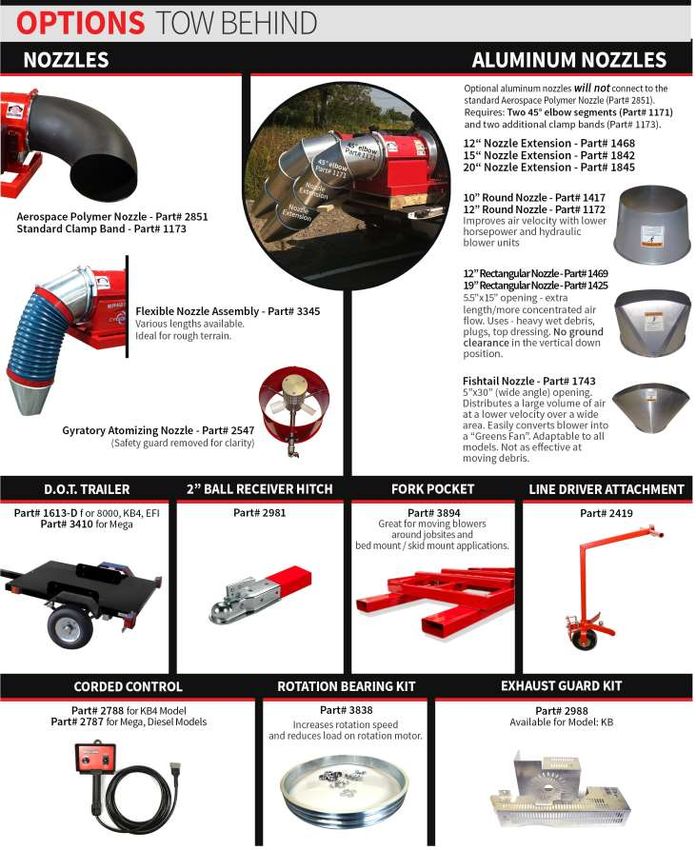
Nozzle Options 33
Buffalo Turbine Additional Products 34
2
1.0      INTRODUCTION
       Congratulations on your choice of a Buffalo Turbine Sprayer and/or Granular machine. This equipment has been
       designed and manufactured to meet the needs of the Insect Control Industry.

       Safe, efficient and trouble-free operation of your Buffalo Turbine Unit requires that you and anyone else, who will
       be operating or maintaining the Blower, read and understand all of the safety, operation, maintenance and
       troubleshooting information contained within this Operator’s manual.

       This Manual covers the BT-CS4 Models.

       Keep this manual handy for frequent reference and to pass on to new operators or owners. Call your Buffalo
       Turbine dealer or distributor if you need assistance, information, or additional copies of the manuals.

                                  SERIAL NUMBER LOCATION
Always give your dealer the serial number of your Monsoon when ordering parts or requesting service or other information.

    The serial number plate(s) is located where indicated in the pictures below. Please document the number in the space
                                                provided for easy reference.

                                                     Serial #

    OPERATOR ORIENTATION – The directions left, right, front and rear, as mentioned throughout the manual, are as
    seen from the driver’s seat and facing in the direction of travel.

                                                  MODEL BT-CS4
                                    RIGHT FRONT TOP SURFACE OF FRAME

                                          Serial Number:        _______________

                                                                3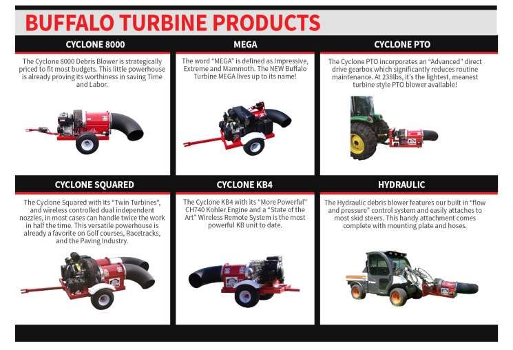
2.0 SAFETY
YOU are responsible for the SAFE operation and maintenance of your Buffalo Turbine Sprayer and /or Granular
unit. YOU must ensure that you and anyone else, who is going to operate, maintain or work around the Buffalo
Turbine Sprayer and/or Granular unit be familiar with the operating and maintenance procedures and related
SAFETY information contained in this manual. This manual will take you step-by-step through your working day
and alerts you to all good safety practice while operating the Monsoon.
Remember YOU are the key to safety. Good safety practices not only protect you but also the people around you.
Make these practices a working part of your safety program. Be certain that EVERYONE operating this machine is
familiar with the procedures recommended and follows safety precautions. Remember most accidents can be
prevented. Do not risk injury or death by ignoring good safety practices.
Sprayer/granular unit owners must give operating instructions to operators or employees before allowing them
to operate the unit, and at least annually thereafter.
The most important safety device on this equipment is a SAFE operator. It is the operator’s responsibility to
read and understand ALL Safety and Operating instructions in the manual and to follow these. All accidents can
be avoided.
A person who has not read and understood all operating instructions is not qualified to operate the machine. An
untrained operator exposes themselves and bystanders to possible serious injury or death.
Do not modify the equipment in any way. Unauthorized modification may impair the function and/or safety
which could affect the life of the equipment.
Think SAFETY! Work SAFELY!
This Safety Alert symbol means ATTENTION! BECOME ALERT! YOUR SAFETY IS INVOLVED!
The Safety Alert symbol identifies important safety messages on the Buffalo Turbine Sprayer and/or Granular unit
and in the manual. When you see this symbol, be alert to the possibility of personal injury or death. Follow the
instructions in the safety message.
3 Big Reasons: Accidents Disable and Kill
Why is SAFETY important to you? Accidents Cost
Accidents Can Be Avoided
SIGNAL WORDS: Note the use of the signal words DANGER, WARNING and CAUTION with the safety
messages. The appropriate signal word for each message has been selected using the following guidelines
1. DANGER –injury or death if the proper precautions are not taken.
2. WARNING -- A specific hazard or unsafe practice that COULD result in severe personal injury or death if
proper precautions are not taken.
3. CAUTION – Unsafe practices that COULD result in personal injury if proper practices are not taken, or as a
reminder of good safety.
The Safety Alert symbol identifies important safety messages on the Buffalo Turbine Sprayer and/or Granular
unit and in the manual. When you see this symbol, be alert to the possibility of personal injury or death. Follow
the instructions in the safety message.
4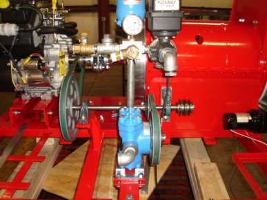
2.1 SAFETY DECALS
The types of decals on the blower unit are shown below. Good safety requires that you familiarize yourself with the
various Safety Decals, the type of warning and the area, or particular function related to that area that requires your
SAFETY AWARENESS.* THINK SAFETY! WORK SAFELY!
!ATTENTION!
1. KEEP HANDS, FEET AND CLOTHING AWAY FROM POWER DRIVEN PARTS.
2. STOP ENGINE AND REMOVE KEY BEFORE LEAVING OPERATOR’S POSITION.
3. MACHINE MUST COME TO A COMPLETE STOP BEFORE ANY MAINTENANCE, TO
INCLUDE ADJUSTING, LUBRICATING OR CLEANING, IS PERFORMED.
4. KEEP PEOPLE AND PETS AT SAFE DISTANCE FROM MACHINE.
5. KEEP ALL GUARDS AND SHIELDS IN PLACE.
Never operate without eye Never operate without ear
protection due to blowing debris. protection due to prolonged Never operate without guards
exposure to excessive noise in place because there are
sharp rotating components
that will cause serious injury.
REMEMBER – If safety decals have been damaged, removed, become illegible or parts replaced without
decals, new decals must be applied. New decals are available from your authorized dealer.
2.2 GENERAL SAFETY
1. Read and understand the Operator’s Manual and all safety signs before operating, maintaining, and adjusting.
2. Provide a first-aid kit for use in case of an accident. Store in a highly visible place.
3. Provide a fire extinguisher for use in case of an accident. Store in a highly visible place.
4. Wear appropriate protective gear. This list includes but is not limited to:
A hard hat
Protective shoes with slip resistant soles
Protective glasses or goggles
Heavy gloves
Wet weather gear
Hearing protection
5. Do not operate without guards or shields properly installed.
6. Do not allow riders.
7. Wear appropriate ear protection for prolonged exposure to excessive noise.
8. (All Models) Set Blower on the ground, stop engine, chock wheels, remove ignition key and wait for all
moving parts to stop before dismounting to service or adjust.
9. Clear the area of people, especially small children, before starting the unit.
10. Review all safety related items annually with all personnel who will be operating or maintaining the Blower.
11. Keep hands, feet, hair and clothing away from moving parts. Operate equipment only while seated in the
operator’s seat.
2.3 OPERATING SAFETY
1. Read and understand the Operator’s Manual and all safety signs before operating, servicing or adjusting.
2. Before servicing or repairing, Set sprayer and/or granular unit on the ground, stop engine, chock wheels,
remove key, and wait for all moving parts to stop.
52.4 MAINTENANCE SAFETY
1. Read and follow ALL general, operating, maintenance and safety information in this manual.
2. Support the machine with blocks or safety stands when changing tires or working beneath it.
3. Set sprayer and/or granular unit on the ground, stop engine, chock wheels, remove ignition key and wait for all
moving parts to stop before operating, servicing or adjusting.
4. Make sure all guards are in place and properly secured when operating or maintaining the Blower.
* NEVER HAVE NOZZLE POINTING AT/NEAR ANYONE DURING STARTUP*
2.5 TRANSPORT SAFETY
1. Use a DOT Approved trailer for Highway Use and for speeds exceeding 15 MPH (24KPH). Make sure you are
in compliant with all local DOT regulations regarding transporting Buffalo Turbine equipment on public roads
and highways.
2. The sprayer and/or granular unit can easily be transported and operated in the bed of a standard pick-up truck or
utility vehicle. Be sure to block, anchor and secure the unit before operating or transporting. Do not use the
top of the Turbine housing to strap or tie down blower unit.
2.6 STORAGE SAFETY
1. Store the sprayer and/or granular unit on a firm, level surface.
2. Store away from areas of human activity. Do not permit children to play on or around the stored machine.
3. Make sure the unit is sitting, or blocked up firm and solid and will not tip or sink into a soft area.
4. Cover with a weatherproof tarpaulin and tie down securely.
5. Make sure nozzle is covered during storage.
2.7 SIGN-OFF FORM
Buffalo Turbine recommends that anyone who will be operating and/or maintaining the Buffalo Turbine
sprayer and/or granular unit must read and clearly understand ALL Safety, Operating and Maintenance
information presented in this manual.
Do not operate or allow anyone else to operate this equipment until such information has been reviewed.
Annually review this information before the season start-up.
Make these periodic reviews of SAFETY and OPERATION a standard practice for all of your equipment.
We feel that an untrained operator is unqualified to operate this machine.
A sign-off sheet is provided for your record keeping to show that all personnel who will be working with the
equipment have read and understand the information in the Operator’s Manual and have been instructed in the
operation of the equipment.
SIGN-OFF FORM
DATE EMPLOYEES SIGNATURE EMPLOYERS SIGNATURE
6Buffalo Turbine Sprayer and/or Granular Unit
3.0 WARRANTY
Buffalo Turbine warrants the Sprayer and/or Granular unit to be free from defects in material and workmanship,
under normal use and service. Obligation under this warranty shall extend for a period of 1 year (12 months) and
shall be limited to, at the option of Buffalo Turbine, replacement of any parts found, upon inspection by Buffalo
Turbine, to be defective.
Buffalo Turbine reserves the right to incorporate improvements in
material and design of its products without notice and is not obligated to
make the same improvements to equipment previously manufactured.
WARRANTY CLAIMS- Buffalo Turbine Must be Notified Prior to Performing any
Warranty Repairs:
The purchaser claiming under this warranty shall submit a warranty claim in the prescribed form to Buffalo Turbine
or an Authorized Dealer for inspection by an authorized company representative.
Factory ordered Buffalo Turbine parts must be used when filing a warranty claim.
LIMITATIONS OF LIABILITY
This warranty is expressly in lieu of all other warranties expressed or implied and all other obligations or liabilities
on our part of any kind or character, including liabilities for alleged representations or negligence. We neither
assume nor authorize any other person to assume on our behalf, any liability in connection with the subsequent sale
of the Sprayer and/or Granular unit.
This warranty shall not apply to any Sprayer and/or Granular unit, which has been altered outside the factory in any
way so as, in the judgment of Buffalo Turbine, to affect its operation or reliability, or which has been subject to
misuse, neglect, or accident.
This warranty does not cover parts and accessories, which are under separate guarantee from the manufacturers and
service can be, obtained from their service facilities. No warranty is extended to regular service items such as
lubricants, belts, paint and the like. (See Page 8)
Original Instruction Manual
The Purchaser acknowledges having receiving training in the safe operation of the Sprayer and/or Granular unit and
further acknowledges that Buffalo Turbine does not assume any liability resulting from the operation of the Sprayer
and/or Granular unit in any manner other than described in the Operator’s Manual supplied at the time of purchase.
WARRANTY VOID IF NOT REGISTERED (see Page 7 for warranty registration form)
If there are any questions regarding any of our products call Buffalo Turbine at 716 592 2700.
DO NOT SPLIT THE TURBINE HOUSING FOR ANY REASON.
DO NOT ATTEMPT TO SERVICE OR DISASSEMBLE THE TURBINE.
DO NOT USE THE TOP OF THE TURBINE HOUSING TO STRAP OR TIE DOWN BLOWER UNITS.
Unauthorized service work on the Sprayer and/or Granular unit will null and void all
warranties.
73.1 Warranty Registration Form
BUFFALO TURBINE
WARRANTY REGISTRATION FORM & INSPECTION REPORT
Any units not registered with Buffalo Turbine are not eligible for warranty claims
WARRANTY REGISTRATION
This form must be filled out by the dealer and signed by both the dealer and the customer at the time of delivery
Customer's Name _______________________ Dealer’s Name __________________________
Address _______________________ Address __________________________
City, State, Zip, Country ____________________ City, State, Zip, Country______________________
Email Address (important) ___________________ Email Address ____________________________
Telephone Number _______________________
Blower Model _______________________ Circle one:
Serial Number _______________________ Commercial Use
Delivery Date _______________________ Private Use
DEALER INSPECTION REPORT SAFETY CHECKS
________ Tire Pressure Check -- Model KB ________ All Decals Installed
_________ Wheel Bolts ________ Review Operating and Safety Instructions
_________ Belt Tension
_________ Lubricate Machine ________ Guards in Place
_________ Fasteners Tight _______ Trailer assembly bolts properly installed and tightened
ALL 3 POINT HITCH MODELS: PTO SHAFTS MUST TELESCOPE IN EVERY POSITION
I have thoroughly instructed the buyer on the above described equipment which reviews the included Operator's Manual
content, equipment care, adjustments, safe operation and applicable warranty policy.
Date __________________ Dealer's Rep. Signature ____________________________
The above equipment and Operator's Manual has been received by me and I have been thoroughly instructed as to the care,
adjustments, safe operation and applicable warranty policy.
Date __________________ Owner's Signature _________________________________
PLEASE FAX A COPY TO BUFFALO TURBINE AT 716 592 2460 Or
Email - service@buffaloturbine.com
83.2 Parts Warranty Information
Who to Contact
Manufacturer’s Warranty
The turbine assembly, blower wheel,
frame, engine mounting rails, rotation Buffalo Turbine
motor mounting bracket, tongue, axle (716) 592-2700
assembly, hub assembly, All belt 1 Year Parts and Labor Or Local Authorized Buffalo
driven components and other Turbine Representative
components manufactured by Buffalo
Turbine*.
Buffalo Turbine
Rotation Motor 1 Year Parts
(716) 592-2700
Yellow/black Box
Buffalo Turbine
Wireless transmitter, Receiver, Wiring 1 Year Parts
(716) 592-2700
harness.
1 Year Parts
Reimbursement with Faxed El-Don Battery
Battery receipt from new battery and (716)-896-0404
Defective Battery Serial #. Fax: (716)-896-0406
Up to $30.00
Buffalo Turbine
Gas Tanks 1 Year Parts
(716) 592-2700
Buffalo Turbine
Battery Box 1 Year Parts
(716) 592-2700
Buffalo Turbine
Tires and Wheels 1 Year Parts
(716) 592-2700
Kohler Dealer
3 Year Engine Warranty
Kohler Engines http://kohlerplus.com
See Engine owner’s Manual
go to: Dealer Locator
Buffalo Turbine
Sandevil Units
(716) 592-2700
EQUIPMENT REGISTRATION, TO INCLUDE THE SERIAL NUMBER OF THE UNIT,
WILL BE REQUIRED FOR ALL WARRANTY REPAIRS. PRE-APPROVAL BY A
FACTORY PERSON (FROM BUFFALO TURBINE) PRIOR TO COMMENCING WITH A
WARRANTY REPAIR, WILL BE REQUIRED BY THE END USER AND AT THE
DEALER / DISTRIBUTOR LEVEL.
REPAIR PARTS MUST BE ORDERED THROUGH AN AUTHORIZED BUFFALO
TURBINE DEALER.
WARRANTY REPAIR PARTS ARE SHIPPED FREE OF CHARGE VIA UPS GROUND*
*If expedited shipping is required the shipping method can be altered with the expedited
charges being paid by the end user*
PLEASE CONTACT BUFFALO TURBINE’S SERVICE DEPARTMENT AT 716 592 2700
FOR ANY SERVICE QUESTION YOU MAY HAVE REGARDING THE BUFFALO
TURBINE BLOWERS.
94.0 OPERATIONS
4.1 TO THE NEW OPERATOR OR OWNER
Buffalo Turbine Sprayer and/or Granular unit are designed to spray a fine mist of water particles and/or granular giving a
thorough and wide-ranged coverage. Being adjustable allows a desired degree of agitation to the foliage, with enough velocity to
completely carry through the tops of trees as well as through row after row of heavy thick leaf cover in row crops.
Many of the features incorporated into the machine are the result of suggestions made by customers like you. Read the manual
carefully to learn to operate the machine safely and how to set it to provide maximum efficiency. The manual will take you step-
by-step through your working day. By following the operating instructions in conjunction with a good maintenance program,
your Blower will provide many years of trouble-free service.
Potential Mechanical Hazards while operating your machine:
Never operate the monsoon around others to prevent the possibility of being run over by equipment.
Never ride on your monsoon to prevent the possibility of being thrown off the machine or hurt severely.
Potential Crushing Hazards while operating your machine:
Between Trailer Tongue and mounting hitch on towing vehicle
WARNING:
This Product can expose you to chemicals including carbon
monoxide and benzene, which are known to the State of
California to cause cancer and birth defects or
other reproductive harm.
For more information go to www.P65Warnings.ca.gov.
4.2 BREAK-IN
Although there are no operational restrictions on the Blower when it is used for the first time, it is recommended that
the following mechanical items be checked:
A. Operating for first ½ hour
1. Re-torque all wheel bolts, axle nuts and trailer mounting bolts and nuts.
2. Re-torque all other fasteners and hardware.
3. Check set screw (nozzle pulley) to ensure it tightened.
B. Operating for first 5 hours
1. Re-torque all hardware and fasteners.
2. Check set screw (nozzle pulley) to ensure it tightened.
3. Go to the normal servicing and maintenance schedule as defined in the Maintenance Section of the manual.
4.3 PRE-OPERATION CHECKS
Efficient and safe operation of the Buffalo Turbine Sprayer and/or Granular unit requires that each operator reads and
understands the operating procedures and all related safety precautions outlined in this section. A pre-operation checklist is
provided for the operator. It is important for both personal safety and maintaining the good mechanical condition of the machine
that this checklist is followed.
BATTERY MUST BE CONNECTED BEFORE OPERATION (DISCONNECTION FOR SHIPPING).
Before Operating the Monsoon and each time thereafter, the following areas should be checked off.
1. For fuel, oil, and operating information of the Kohler Engine, refer to the Manufacturers specs included with this manual.
2. The Model CS4 machines are designed to be skid mounted. For highway use or speeds above 15mph (24kph) an optional
DOT approved trailer must be used.
3. Make sure all guards and shields are in place, secured and functioning as designed.
4. Check that all clamp bands are secure.
5. Check the belts and pulleys for proper tension and alignment.
CAUTION ! DO NOT ALLOW LEAVES OR DEBRIS TO ACCUMULATE ON OR NEAR THE
ENGINE OR EXHAUST SYSTEM OF THE MODEL KB BLOWER, TRACTOR ENGINE OR ANY
INTERNAL COMBUSTION ENGINE.
104.4 MODEL BT-CS4 Assembly Instructions
1112
4.5       FIELD OPERATION
1. Do not direct monsoon towards people, pets, autos, windows, etc.
2. Starting Sprayer and/or Granular unit: Always start engine at a lower engine speed with nozzle pointed down or away.
3. The air stream direction is changed (in either direction) by pressing the nozzle buttons on the transmitter. The nozzle will stop
turning by releasing the transmitter button. ALWAYS CHECK THE GROUND CLEARANCE WHEN OPERATING THE NOZZLE
IN THE DOWN VERTICAL POSITION.
4. Stopping Sprayer and/or Granular unit: Shut engine off above ½ throttle by turning key switch to off position to avoid engine
backfire.
5. Allow the blower fan speed to come to a complete stop before disconnecting from tow vehicle.

4.6       Operating RPM (All Models)
The manufacturer’s engine section normally recommends the unit be run at a RPM that will insure efficient operation. The Sprayer and/or
Granular unit can operate at a slower RPM. Increase engine RPM as needed. Always try to blow with the wind.

4.7       Storage
At the end of each day and before storing the Sprayer and/or Granular unit, prepare the machine by following this procedure:
1. Select a storage area that is dry, level and free of debris.
2. Thoroughly wash the machine with a water hose to remove all debris and residue. DO NOT PRESSURE WASH
3. Run the machine at low RPM to dry the Blower Components.
4. Touch up all paint chips and scratches to prevent rusting.
5. Inspect for worn or failed components. Order the replacement parts and repair the monsoon unit when time allows. This will eliminate
unnecessary down time at the start of next season.
6. Store in an enclosed building. If space is not available, cover with a waterproof tarpaulin and tie it down securely.
7. Store the machine away from areas of human activity.
8. Do not allow children to play around the stored unit.

5.0       TROUBLE SHOOTING
The Buffalo Turbine Sprayer and/or Granular unit uses a high volume and velocity of air to move material from one place to another. The
system is simple and reliable requiring minimal maintenance. If you encounter a problem that is difficult to solve, even after reading through
this trouble shooting section, please call your local dealer or distributor. Before calling, please have this Operator’s Manual and the serial
number from your Blower ready. In the following section, we have listed causes and solutions to the problems that you may have
encountered.
         TURN OFF ENGINE, REMOVE KEY, AND DISCONNECT BATTERY BEFORE SERVICING BLOWER UNITS.
                                                 INSTALL GUARDS BEFORE OPERATING
           PROBLEM                            CAUSE                                                    SOLUTION
  No air flow                 Buildup of debris inside turbine       Remove nozzle and clean debris from inside turbine
                              Broken coupling (KB Series)            Replace coupling
                              Blower fan not turning
  Reduced or no air flow      Blower fan turns                       Air intake or exhaust restricted
                                                                     Shut off engine
                                                                     Blower or tractor – remove restrictions
                                                                     Debris cannot be allowed to build up between the blower fan and stationary vanes
  Machine vibrates or         Bearing or coupling failure            Replace bearings or coupling
  Unusual sounds              Out-of-balance                         Have your dealer check blower for damaged blades.
                                                                     Wash and clean blower fan blades
  No Liquid Spray             Toggle switch not turned on            Turn switch on from control panel
                              Holding tank plugged or empty          Check hoses and fill tank
                              Loose or broken belt                   Adjust or replace belts
                              Pulleys slipping                       Tighten set screws on pulleys
                              Defective or worn pump                 Rebuild or replace pump
                              Dirty strainer or nozzle screens       Clean or replace strainer/nozzle screens
  Granular Bin troubles       Clutch not engaged                     Turn switch on from control panel
                              Granulars packing solid                Check agitators
                              Loose or broken belts                  Adjust or replace belts
                              Pulleys slipping                       Tighten set screws on pulleys
                              Inconsistent application               Check and clean control gates
  Belts or Pulleys overheat   Belts slipping                         Adjust belt tension
  Engine will not start       Dead battery                           Charge or replace battery
                              Battery cables dirty or disconnected   Clean and connect terminals

                                                                      13
6.0 Machine Specifications
Model CS4 Series
Length(without trailer): 114” with nozzle assembly & 100 gallon tank attached
Length (with DOT Trailer) 166” with nozzle assembly & 100 gallon tank attached
Width(without trailer): 38”
Width(with DOT Trailer): 80”
Height(Without trailer): 38 1/2” (with Granular bin 53”)
Height(With DOT Trailer): 54” (with Granular bin 73”)
Weight (without trailer): TBD
Weight (with DOT Trailer): TBD
Weight(with granular bin & 100 Gallon tank): Approx. 820 lbs.
Weight(with granular bin and DOT trailer): TBD
Electrical System: 12 Volt battery / 300 CCA
Fuel Capacity: 12 gallon Unleaded Fuel only
Input Power: ECH749 Kohler Engine (EFI does not have a choke)
Input RPM: Up to 3900 RPM (more fuel economy when ran below 3600 RPM)
Outlet Size: Approximately 12”
147.0 MAINTENANCE SECTION
7.1 Maintenance Safety
1. Set Blower on a level surface, stop engine, set park brake, remove ignition key and wait for all moving parts to
stop before dismounting to service, adjust or repair.
2. Reinstall and secure all guards removed for servicing before starting to use machine again. *We recommend
wearing gloves when removing or installing the guard to avoid getting cut*
3. Securely support machine with blocks or safety stands when changing tires or working beneath it.
7.2 Fluids
Change oil per Manufacturer’s specification (see Engine owner’s manual section).
A Teflon spray type lubricant on the nozzle base and slides provides for freer rotation.
Use only a hand-held grease gun for all greasing (USE NLGI2 grease only)
7.3 SERVICE CHECKLIST
See Lubrication and Maintenance sections for details of service. Copy this page to continue record.
TURN OFF ENGINE, REMOVE KEY & DISCONNECT BATTERY BEFORE SERVICING BLOWER UNIT
CODE: LUBRICATE-(L) / CHECK-(*) / CHANGE-(C) / REPLACE-(B) / CLEAN-(CL)
SCHEDULED MAINTENANCE HOURS ________________________
SERVICED BY ____________________
MAINTENANCE
8 hrs or daily
(*) Remove all debris that has settled between the blower wheel fan and the stationary vanes.
Helps maintain peak performance.
(*) Check engine oil and fill to proper level – Do not overfill
(*) Check air filter and precleaner
(CL) Clean debris from air intake and other cooling areas on the engine
(*) Check tire pressure (Max. 50 PSI)
(*) Check Clamp Band Bolt for tightness
40 hours or weekly
(*) Check condition of coupling (center section # 1256) connecting bolts and nuts during each oil change
or when experiencing vibration or unusual noises. (See page 15)
(*) Inspect battery terminals for any corrosion, broken wires, or loose connections.
(*)Remove Battery and clean debris from inside of battery box
(L) Nozzle base slides (Teflon or silicone spray)
(*) Check set screw (nozzle pulley) to ensure it is tightened
(*) Wash and Clean any dirt or grime build up that has accumulated on blower wheel
fan blades. Helps to minimize vibration balance and maintain peak performance.
100hrs or monthly
(L) Pump (Hypro 5210) grease fitting on cam bearing. With a flat tool, apply a generous dab of grease to
the outer diameter surface of the cam bearing at the top and bottom, where the bearing contacts
connecting rod.
(L) Granular Bin
200hrs or annually
(CL) Machine
DO NOT OPERATE SPRAYER AND/OR GRANULAR UNIT WITHOUT GUARDS SECURELY ATTACHED
157.4 Belt Tension
Efficient machine operation requires that the belts always be properly tensioned.
V -belts 6930 and 6945 are used to drive the Hypro pump (shown below).
1 5
4
3
2
To adjust belt #1 (6945), loosen bolts on bearing #3 then move bearing in the direction of the arrow. Tighten bolts securely
and check for proper tension.
To adjust belt #2 (6930), loosen pump mounting bolts at the base of the pump and move in the direction of the arrow. Tighten
bolts securely and check for proper tension.
Always check the pulleys and jack shaft alignment after any adjustments are made. Replace belts that are broken, worn or
stretched.
7.5 Changing the Belts
After using the Model CS4 for a long period of time, the belts will stretch and wear. To change belts, follow this procedure:
1. Turn off engine and remove key for SAFETY. Remove the guards around belt and pulleys.
2. Refer to the picture section 7.4 for changing the belts. To replace belt #1 (6945), loosen bearing #3 then slide the bearing toward the
output shaft of the engine. The center section of the coupling (#5) will have to be removed in order to remove the old belt and install a
new one. Page 28 has a detailed picture of the coupling. The center section of the coupling must be disassembled and assembled with
extreme care. Damage to the coupling can result in premature bearing failure in the turbine and engine. A new bolt kit for the coupling is
recommended before reassembling the coupling. ALWAYS USE TOPLOC NUTS. Remove the bolts from the coupling (2 ea. side of
flange). Loosen setscrews on one flange only. A thread lock material is used on the threads at assembly. Heat may be needed to break that
bond. Clean all dirt and rust that has accumulated on the shaft (behind the flange) then slowly wedge the center section off of the flange.
Note: The flanges are counter bored to match the flange bushings. Once the center section is removed, belt #1 can be removed and a new
belt can be installed. DO NOT TENSION THE BELT UNTIL THE CENTER SECTION OF THE COUPLING IS INSTALLED. Bolt
the center section per the picture on page 28.DO NOT TIGHTEN THE SET SCREWS AT THIS TIME. Note position of bolts and
locking nuts. Once the coupling is installed and securely tightened, check to see if the key is in position on the shaft and in the keyway of
the flange. Coat the setscrews with Loc Tite (red) and securely tighten. Re check all the setscrews and coupling bolts before proceeding.
3. To replace belt #2 (6930), loosen mounting bolts (#5) under the Hypro pump and slide toward the Turbine. Remove old belt then
install the new belt. Adjust the belt tension by sliding the pump assembly away from the Turbine Assembly. See section 4.2.1. in the
previous section for more information. Check the pulley alignment and recheck both belts and the tightness of all bolts and set screws.
ASSEMBLE ALL GUARDS BEFORE OPERATING UNIT!
4. To replace (4L870) Granular Bin belts (optional Granular models only) remove granular bin cover. Remove two 3/8” bolts on
jackshaft right side bearing. Slide old belts off. Replace with new belts and reinstall two 3/8” bolts in pillow block, apply pressure straight
down on jackshaft to give proper belt tension and tighten pillow block bolts. Reinstall guards.
5. Install all guards before operating blower unit!
16INSTALLATION INSTRUCTIONS & PARTS FOR THE MOREFLEX COUPLING
COUPLING COMPLETE, KOHLER ENGINE
PN 1110(1pc), 3805 (1pc), 1112(4pc), 1113(4pc), 1114(1pc), 1115(1pc), 1256(1pc), 2869(4pc)
ALIGNMENT OF TURBINE SHAFT WITH SHAFT OF ENGINE IS CRITICAL
1. Install keys in both shafts.
2. Slide coupling flanges on both shafts (engine and turbine shafts)
3. Place Morflex coupling CENTER SECTION between coupling flanges and secure with 4 bolts and
TOPLOC nuts. The bolt heads are positioned against the coupling in alternating directions. Tighten all
4 bolts. DO NOT TIGHTEN SET SCREWS AT THIS TIME.
4. Check key for proper position under the set screw hole on both shafts.
5. Place several drops of Loctite 271 into these two holes only. Set screws and tapped screw holes must
be free of dirt and oil for Loctite to work properly.
6. Install the set screws over the keys and tighten firmly.
7. Using a drill point, dimple each shaft through the other 2 set screw holes. Clean drill chips, oil and dirt
before applying Loctite.
8. Place several drops of Loctite 271 in these 2 holes.
9. Install and tighten set screws in these 2 holes.
10. Check and retighten the 4 bolts that hold the coupling center section in place.
11. Visually inspect the unit and replace the guard. DO NOT OPERATE WITHOUT THE GUARDS IN
PLACE.
Center Section
7/16 –20 TopLoc Nut
#1256
(4) required - #1112
Key – Engine 7/16-20 x 2 ½ HHCS
3/8 - #3805 Zinc – (4) required - #1113
Key – Turbine
¼ x 1 ¾ - #1110
7/16-20 x 3/8" Socket Set Screw
# 2869
Coupling flange, 1 7/16” bore
Engine - #1115
Coupling flange, 1 ¼
Turbine - # 1114
Part # 1256 (center section) is a “WEAR” item that should be visually checked each time the engine oil is changed. This
coupling is equipped with special lock nuts. Occasionally check that all 4 nuts are securely fastened. LOOK FOR
CRACKS IN THE RUBBER COMPOSITION THAT SURROUNDS THE 4 BUSHINGS. Replace the center section
when the rubber composition begins to show ANY signs of cracking OR an increase in vibration OR unusual
sounds. When in doubt, call our Service Department.MOUNTING BLOWER ASSEMBLY ONTO FRAME
AND ALIGNMENT RECOMMENDATIONS
1. Install blower assembly onto frame and tighten all of the bolts.
2. Remove all burrs and oil from the shafts and keyways (engine and blower shafts).
3. Using the supplied gauge, align the shafts parallel to each other (very important).
4. Check in four places around the shafts at 90 to each other.
5. When properly aligned, gauge should have little to no gap between itself and the shafts at
any point along the gauge.
6. To adjust, move the engine. The 2 mounting brackets have tapped holes in each corner to
help support and adjust the position of the engine. The 4 roll pins may need to be
repositioned after alignment is completed and bolts are tightened.
7. Tighten all engine bolts and recheck alignment. Drill and install 4 roll pins in new position.
ACCEPTABLE
GAUGE
CRANKSHAFT BLOWER SHAFT
NOT ACCEPTABLE
GAUGE
CRANKSHAFT BLOWER SHAFT
SECURELY ATTACH GUARDS BEFORE OPERATING BLOWER UNITS
18BILL OF MATERIALS FOR BT-CS4
REF PAGE # PN DESCRIPTION QTY
1100 3/8-24 X 1-1/4 HHCS ZINC GR 5 16
1101 3/8-24 X 1-1/2 HHCS ZINC GRADE 5 7
1102 3/8-24 X 1-3/4 HHCS ZINC GRADE 5 8
1103 3/8-24 X 2 FACED HEAD SCREW ZINC GRADE 5 2
1104 3/8-24 X 2 HHCS ZINC GRADE 5 9
1105 3/8-24 HEX NUT ZINC PLATED GRADE 5 33
1107 3/8 LOCK WASHER ZINC PLATED 42
1108 3/8 FLAT WASHER ZINC PLATED 46
1109 3/16 X ½ ROLL PIN 4
1110 KEY, 1/4 X 1-1/2 2
1112 7/16-20 TOPLOC NUT GRADE 5 ZINC 4
1113 7/16-20 X 2-1/2 HHCS ZINC GRADE 5 4
1114 COUPLING FLANGE 1-1/4 BORE 1
1115 COUPLING FLANGE 1-7/16 BORE 1
24 1119 14-221-D1 BELLMOUTH 1
1123 M8 X 1.25 X ¾ HHCS 1
21 1125 ¼-20 NYLOC NUT ZINC 16
1130 5/16-18 X 3/8 SET SCREW 1
1131 3/8-16 X 3/8 SET SCREW 1
1132 300 CCA BATTERIES FOR KB'S UIL-4 1
24 1138 PLASTIC SLIDES 3
1139 3/8 NOTCHED WASHER 10
24 1142 AX54 V-BELT 1
24 1144 ROTATION MOTOR BRACKET 1
24 1145 SHEAVE AK32 X ½ 1
1146 10-32 X 5/8 SHCS 4
1156 SERIAL TAG 1
1158 ¼” GAS LINE 56
1166 COV ½ X ¼ WIRE CLAMP 5
1168 HC-4M SS HOSE CLAMP 5
1169 ¼-20 X 1HHCS ZINC 10
1170 ¼-20 HEX NUT 2
21 1173 CLAMP BAND W/ BOLT & NUT 1
1187 8 X 10 BT DECAL 1
21 1193 1/16 X ½ COTTER PIN 1
21 1194 3/16 X 1-1/2 COTTER PIN 1
1218 BOLT, ½ PUSHOVER 1
21 1222 ½ LOCK WASHER ZINC 4
1223 1 X ½ X 3/16 THICK WASHER 2
1226 ½ FLAT WASHER 3
21 1231 ½-13 HEX NUT 2
1237 ½-20 HEX NUT 2
24 1239 FRAME, CSII SPRAYER 1
23 1247 ¾ PILLOW BLOCK BEARING 2
1256 MOREFLEX CENTER SECTION 1
1258 ¼-20 X ¾ HHCS 4
1259 ¼ LOCKWASHER 6
24 1308 PUMP MOUNT PLATE FOR CSII 1
24 1315 PUMP MOUNT PUSHOVER PLATE 1
24 1359 ENGINE RAIL 2
21 1378 PLASTIC BATTERY BOX AND COVER 1
21 1409 LINEAR ACTUATOR – 4” STROKE 1
21 1414 REMOTE THROTTLE PIN 1
1415 ¼”FLAT WASHER 17
21 1451 ACTUATOR MOUNT, PIN 1
23 1487 MANIFOLD BLOCK, ALUMINUM 1
1499 NUT PLATE, 3/8 4
24 1510 PUMP MOUNT BAR FOR CSII 1
23 1520 HYPRO PUMP 5210C 1
23 1521 ¾” PRESSURE RELIEF VALVE 1
22,23 1522 HYPRO SURGE TANK 1
22,23 1523 0-300 PSI PRESSURE GUAGE 1
1540 5/16 LOCK WASHER, ZINC 1
23 1555 SHEAVE, BK 100H 1
1558 807-31 1/2" FEMALE COUPLAMATIC HOSE END 1
1559 3/4" MALE PUSH ON FITTING 3
22 1560 3/4" FEMALE PUSH ON SWIVEL FITTING 5
23 1562 SHEAVE, BK40 H 1
23 1563 H 3/4 “ BUSHING 2
23 1586 PULLEY, 3-3/8 X .850 WIDE 1
23 1589 6945 GATES V-BELT 1
22 1593 3/4" BRASS HEX NIPPLE 5
1596 3/16 SQUARE X 1-3/8 KEY 2
1597 ALUMINUM SPACER 3/8 X 1-1/2 X 5.1 1
1599 ½-20 X 1-3/4 HHCS ZINC GR 5 2
23 1648 H X 1” BUSHING 1
1669 ¼-20 X .055 HEAD INSERT 2
1720 ½” GOODYEAR ORTAC HOSE 60
1727 PUMP PUSHOVER BOLT FOR CSII 1
1732 ¾” GOODYEAR ORTAC HOSE 111
21 1825 PUMP GUARD ACCESS PANEL 1
22 1935 3/8-24 NYLOC NUT ZINC PLATED 6
19REF PAGE # PN DESCRIPTION QTY
21 1985 SQUARE PUMP GUARD 1
2076 INSULATED FEMALE QUICK DISCONNECT TERMINAL 2
23 2222 JACK SHAFT, DUSTER 1
2306 8-32 X 7/8” LONG PHILLIPS 6
2329 8-32 NYLOC NUT, ZINC 6
2395 1/2" MALE VARI CRIMP COUPLING 1
2675 3/4" STREET "L" 304 STAINLESS 2
2677 3/4" BRASS HOSE ADAPTER 1
21 2851 PLASTIC NOZZLE 1
2869 7/16-20 X 3/8” SOCKET SET SCREW 4
3007 CONSTANT TENSION HOSE CLAMP 1
21 3308 ¾” HEAVY DUTY BULKHEAD 1
3312 3/8-24 THREADED BASE STOP 1
24 3313 ELBOW BASE W/ 2 TABS WELDED 1
21 3332 3/16" ID FUEL LINE,SAE30R7, LOW PERMATION, CARB APPROVED HOSE 43
24 3434 RH BLOWER ASSEMBLY COMPLETE 1
3514 HOSE CLAMP 8
3521 3/8-24 X 1-1/2 FACED HEAD SCREW 2
3667 HOUR METER, 1:2 RATIO 1
21 3733 LEFT SIDE EFI GUARD 1
3802 ¼-20 X 2-3/4” LG HHCS 4
23 3803 BK90H SHEAVE 1
23 3804 6934 V-BELT 1
3805 3/8 KEY, SPRAYER/GRANULAR 1
23 3806 DISTRIBUTION BLOCK BRACKET 1
21 4136 SPRAYER NOZZLE WELDMENT 1
21 4137 12 GALLON ALUMINUM TANK 1
23 4154 3/4" X 3/4" "T" STRAINER W/50 MESH SS SCREEN 1
21 4155 SPRAY TIP NOZZLE, TXR CONEJET, GREEN ACETAL-CERAMIC HOLLOW CONE 8
21 4156 SPRAY TIP CAP 8
21 4157 STRAINER/CHECK VALVE 50 MESH 8
21 4158 ¼” MALE THREADED ADAPTER 8
23 4159 3-WAY SHUTOFF VALVE 1
21 4160 SPRAYER TRANSITION GUARD 1
21 4167 BULKHEAD MOUNT 1
21 4168 MOUNT PLATE 1
4170 BT SMARTFLOW II CONTROLLER W/BT-RESM & BT-TAM 1
22 4172 3/4" X 1/2" REDUCING BUSHING, STAINLESS STEEL 1
4173 3/4" ELBOW, STAINLESS STEEL 1
22 4175 3/4" CLOSE NIPPLE, STAINLESS STEEL 3
22 4176 1/2" STREET ELL, STAINLESS STEEL 2
22 4177 3/4" X 3" NIPPLE, STAINLESS STEEL 4
22 4178 1/2" X 1-1/2" NIPPLE, STAINLESS STEEL 1
22 4179 3/4" 45 DEGREE ELBOW, STAINLESS STEEL 2
21 4180 LED LIGHT STRIP ASSEMBLY 1
24 4181 ROTATION MOTOR W/ WEATHER PACK CONNECTOR 1
24 4185 EFI ENGINE, STOCK MODEL 1
4187 GARDEN HOSE COUPLING SET, QUICK DISCONNECT BRASS WITH 3/4" THREAD 1
21 4188 1/2" TO 1/4" STRAIGHT REDUCER WITH SEALANT, BRASS NPT THREADS 1
21 4189 3/4" NPT X 1/2" ID HOSE BARB FITTING BANJO# HB 075-050 1
23 4190 3/4" NPT X 1/2" ID HOSE BARB FITTING BANJO# HB 075-050-90 1
4191 1/2" ID GREEN HOSE 600 PSI PVC SPRAY REINFORCED HOSE, .79" OD 41
4192 1/4" FLAT WASHER, 18-8 STAINLESS STEEL 12
4193 1/4-20 X 3/4" LONG HEX DRIVE ROUND HEAD SCREW, STAINLESS STEEL 6
4194 1/4-20 NYLOC NUT, 18-8 STAINLESS STEEL 6
21 4195 PRESSURE SWITCH SET AT 1.8" H2O 1
22 4196 ¾” PLUG, STAINLESS STEEL 1
21 4198 GUARD COVER PLATE 1
4208 PLUG BUTTON 1
4209 PLUG: KEY SWITCH 1
24 4210 MUFFLER KIT, EFI, FILTER SIDE/STRAIGHT 1
21 3294 100 GALLON TANK ASSEMBLY 1
21 4211 BRASS BARBED HOSE ELBOW, 90 DEGREE ANGLE, 1/4" HOSE ID, 1/4 NPT MALE END 1
21 4212 BRASS BARBED HOSE ELBOW, 90 DEGREE ANGLE, 3/8" HOSE ID, 1/4 NPT MALE END 1
21 4213 HIGH-PRESSURE BRASS THROUGH-WALL ADAPTER, 1/4 NPT FEMALE X MALE 1
22 3293 STEEL PIPE CLAMP 4
21 4240 TEEJET ADAPTER, ELBOW 8
21 4241 TEEJET ADAPTER, EXTENSION 8
22 4242 SPACER 2
22 4245 MOUNT PLATE WELDMENT 2
4246 3/16” VINYL COATED LOOP CLAMP 1
22 4247 ¾” NPT 304 STAINLESS STRAIGHT CONNECTOR 1-1/2” LONG 1
2021
22
23
24
25
26
27
28
29
30
31
32
33
34
You can also read