Development of the HondaJet
←
→
Page content transcription
If your browser does not render page correctly, please read the page content below
Development of the HondaJet
                                      Michimasa Fujino
                    Honda R&D Americas, Inc., Greensboro, North Carolina 27409

                                      Keywords: Airplane Design

Abstract                                             aircraft has great potential to revolutionize air
The HondaJet is an advanced, lightweight,            transportation.
business jet featuring an extra large cabin, high    A unique configuration, called an over-the-wing
fuel efficiency, and high cruise speed compared      engine-mount configuration (OTWEM), was
to existing small business jets. To achieve the      developed to provide a larger cabin than that of
high performance goals, an over-the-wing             conventional configurations. By mounting the
engine-mount configuration, a natural-laminar        engines on the wing, the carry-through structure
-flow wing, and a natural-laminar-flow fuselage      required to mount the engines on the rear
nose were developed through extensive analyses       fuselage is eliminated, which allows the cabin
and wind-tunnel tests. The wing is metal, having     volume to be maximized. It was a technical
an integral, machined skin to achieve the            challenge to employ an over-the-wing engine
smooth upper surface required for natural            -mount configuration for a high-speed aircraft
laminar flow. The fuselage is constructed            from both aerodynamic and aeroelastic
entirely of composites; the stiffened panels and     standpoints. Extensive analytical and experime-
the sandwich panels are co-cured integrally in       ntal studies, however, show that an over-the-
an autoclave to reduce weight and cost. The          wing engine-mount configuration reduces the
prototype aircraft has been designed and             wave drag at high speeds and achieves higher
fabricated. Major ground tests such as               cruise efficiency when the nacelles are located
structural proof tests, control-system proof test,   at the optimum position [1].
system function tests, and ground vibration tests
have been completed. The first flight was
conducted on December 3, 2003, and flight
testing is currently underway. The aerodynamic,
aeroelastic, structural, and system designs and
the ground tests performed during the
development are described.

1 Introduction
The business jet is becoming a common tool for
business people. Chartering business jets,
however, is still expensive and the arrival of a
new generation of small jets that are more                             Fig.1 HondaJet
affordable to operate than conventional jets is
awaited. Market surveys and focus-group              To reduce drag and thereby achieve higher fuel
interviews, conducted in five major cities in the    efficiency, a new natural-laminar-flow (NLF)
United States, show that demand for comfort, in      wing [2] and a natural-laminar-flow fuselage
particular, a large cabin, as well as high fuel      nose were developed through theoretical and
efficiency are critical to the success of small      experimental studies. By employing these
business-jet development. The HondaJet (Fig.1)       advanced technologies, the specific range of the
is designed to satisfy these needs. This new         HondaJet is far greater than that of existing
small jets.                                          volume compared to those of other
                                                     four-passenger seat arrangements and it is also
To achieve natural laminar flow on the wing,
                                                     possible to add two more passenger seats
surface waviness as well as steps and gaps in the
                                                     without sacrificing comfort. The cabin is
wing structure must be minimized. Appropriate
                                                     pressurized up to 8.7 psi to maintain an 8,000-ft
criteria were derived from flight tests. The
                                                     cabin altitude up to 44,000 ft.
upper skin is a machine-milled, integral panel
that maintains the contour necessary for the
achievement of laminar flow. The actual wing
structure was tested in the wind tunnel to
confirm that laminar flow is achieved on the
actual wing surface.
To reduce weight and manufacturing costs, an
advanced composite structure is used for the
fuselage, consisting of a combination of
honeycomb sandwich structure and stiffened
panels.
This paper describes the design, ground tests,
and flight test of the HondaJet with particular
emphasis on these advanced technologies.                        Fig. 3. HF-118 turbofan engine.

2 General Arrangement and Performance                3 Aerodynamic Design
The general arrangement is shown in Figure 2.        3.1 Over-the-wing Engine-Mount Configura-
The aircraft is powered by two Honda HF-118          tion
fuel-efficient turbofan engines, each rated at
1,670 lb thrust at takeoff power (Fig. 3). The       Engine location was the major design decision
engine is controlled by the Full Authority           in the development of the HondaJet configurati-
Digital Engine Control (FADEC) system. The           on. In general, locating the engine nacelles over
aircraft is a low-wing configuration with the        the wing causes unfavorable aerodynamic
engines mounted over the wing. The aircraft is       interference and induces a strong shock wave
41.14 ft long, has a wing span of 39.87 ft, and is   that results in a lower drag-divergence Mach
13.21 ft high at the top of the T-tail. Design       number. Theoretical studies were conducted
maximum takeoff weight is about 9200 lb. The         using a three-dimensional Euler solver [3],[4] to
estimated maximum speed is about 420 knots at        investigate this configuration (Fig. 4). A transo-
30,000 ft and the maximum range is about 1100
nm. The aircraft provides a very large cabin

                                                     Fig. 4. Off-body pressure contour of the OTWEM
              Fig. 2. General arrangement.           configuration.
nic wind-tunnel test (Fig. 5) was conducted in                      three-dimensional, panel method [5],[6] combin-
the Boeing Transonic Wind Tunnel (BTWT) to                          ed with the pressure-difference rule [7], a taper
validate the theoretical predictions. It was found                  ratio of 0.38 and a washout of 5.1 degrees were
that the shock wave is minimized and drag                           chosen to provide good stall characteristics with
divergence occurs at a Mach number higher                           minimum induced drag penalty. The stall
than that for the clean-wing configuration when                     pattern of the over-the-wing engine-mount
the nacelle is located at the optimum position                      configuration obtained from a 1/6-scale, low-
relative to the wing. The over-the-wing engine-                     speed wind-tunnel test is shown in Figure 6. The
mount configuration exhibits lower drag than                        wing stalls first around 55-percent semi-span.
does the conventional rear-fuselage engine-                         The separation propagates inboard, although the
mount configuration [1] . The final aircraft                        root region of the wing between the fuselage
configuration is based on this result. By                           and the nacelle is not stalled at the aircraft stall
employing this optimum over-the-wing engine-                        angle of attack. Thus, the over-the-wing engine-
mount configuration, the cruise efficiency is                       mount configuration exhibits good stall charact-
higher than that of a conventional rear-fuselage                    eristics. In addition, there is adequate stall
engine-nacelle configuration and, in addition,                      margin over the outboard portion of the wing.
the cabin volume is maximized.                                      The lift curves obtained from the 1/6-scale test
                                    ・ Model scale:0.123
                                                                    with and without nacelles are shown in Figure 7.
                                    ・ Mach Number:                  The zero-lift angle of the over-the-wing
                                             0.70~0.84(∆M=0.01)
                                    ・Static pressure Measurement:   engine-mount configuration is about 1.2 degrees
                                            Total 422 orifices
                                    ・ Six component force           higher than that of the clean-wing configuration.
                                       and moment measurement       The maximum lift coefficient of the
                                                                    over-the-wing engine-mount configuration is
                                                                    about 0.07 higher than that of the clean-wing
                                                                    configuration. Thus, there is no disadvantage
                                                                    with respect to the lift characteristics due to the
 ・ Flow visualization                                               nacelle installation over the wing.
     - UV oil flow for shock location
     - Infrared camera for transition location

    Fig. 5. Transonic wind tunnel test model (BTWT).

3.2 Wing
The main goal for the aerodynamic design of
the wing is to achieve minimum drag while
maintaining good stall characteristics. Detail
design studies were performed to minimize the
induced drag with minimum wing weight. The                                                       Mach number=0.186
                                                                                                 Reynolds number=1.03×10⁶
study showed that the takeoff weight is
minimized for a 1100-nm-range aircraft when
the wing geometric aspect ratio is 8.5 and a                                         Fig. 6. Stall pattern.
winglet having a height of 9-percent of the wing                    To satisfy the requirements of the HondaJet, a
span is installed. Because of the over-the-wing                     new natural-laminar-flow airfoil, the SHM-1,
engine-mount configuration, the stall characteri-                   was designed using a conformal-mapping
stics were carefully studied by theoretical                         method [8]. The pressure gradient on the upper
analysis and low-speed wind-tunnel tests. From                      surface is favorable to about 42-percent chord,
the theoretical analysis using a vortex-lattice                     followed by a concave pressure recovery, which
method combined with a critical-section method,                     represents a compromise between maximum lift,
which was developed by the author, and a                            pitching moment, and drag divergence. The
1.4

                     1.2

                      1

                     0.8

                     0.6
  Lift coefficient

                     0.4

                     0.2
                                                         Without Nacelle
                      0
                                                         With Nacelle
                 -0.2
                                           Mach number=0.186                       Fig. 8. SHM-1 airfoil shape and pressure contour.
                 -0.4                      Reynolds number=1.03×10⁶

                 -0.6
                           -10   -5   0      5      10      15     20      25
                                          Angle of attack [deg]

Fig. 7. Comparison of lift curve with and without nacelle
configuration.
pressure gradient along the lower surface is
favorable to about 63-percent chord to reduce
drag. The leading-edge geometry was designed
to cause transition near the leading edge at high
angles of attack to minimize the loss in
                                                                                   Fig. 9. T-33 aircraft modified for NLF flight test.
maximum lift coefficient due to roughness. The
upper-surface trailing-edge geometry was
                                                                                                        Total pressure rake
designed to produce a steep pressure gradient                                                           (5 rakes×8 rows @RH fan face )
and, thereby, induce a small separation. By the
incorporation of this new trailing-edge design,
the magnitude of the pitching moment at high                                                                                   DC motor
speeds is greatly reduced [2]. The shape of the
SHM-1 airfoil and an example of the pressure
distribution are shown in Figure 8. The airfoil
has been tested in low-speed and transonic                                               Static pressure orifices
wind-tunnels. In addition, a flight test using a                                    (13 orifices× 4 rows @LH inlet)
gloved T-33 aircraft (Fig. 9) was conducted to                                                 Hyscan electronic
validate the performance of the airfoil at                                                     pressure scanner
full-scale Reynolds number and Mach number.
The airfoil exhibits a high maximum lift                                                  Fig. 10. 1/6-scale engine simulator.
coefficient with docile stall characteristics and                               the over-the-wing engine-mount configuration.
low profile-drag coefficients in cruise and                                     To evaluate these characteristics, a 1/6-scale,
climb.                                                                          powered-model test using DC motor engine
                                                                                simulators was conducted in the Honda
3.3 Engine Simulator Test for OTWEM                                             Low-Speed Wind Tunnel (Fig.10). An
Configuration                                                                   investigation was conducted to determine if the
It is important to investigate the inlet-flow                                   measured total-pressure distortion exceeded the
distortion at high angles of attack especially for                              limits for high and low mass-flow conditions at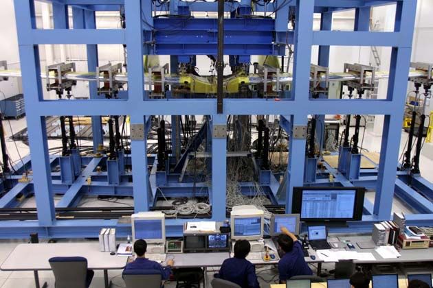
various angles of attack and sideslip angles.                         instabilities. A 1/3-scale test was conducted in
Examples of the distortion pressure patterns at                       the Honda Low-Speed Wind Tunnel to validate
four angles of attack (10, 15, 18, and 26                             the design (Fig. 12). The streamlines on the
degrees) and three sideslip angles (-18, 0, and                       nose were visualized using the oil-flow
18 degrees) with a mass-flow ratio of 1.15,                           technique (Fig. 13) and the observed patterns
which corresponds to approach speed at                                were compared to those from the theoretical
required thrust, are shown in Figure 11. The                          analysis [5], [6]. The infrared technique was also
inlet total-pressure distortion is less than 0.1                      used to visualize the laminar flow on the nose at
percent up to the stall angle of attack of 15                         each angle of attack (Fig. 14). The results show
degrees and less than 2 percent up to a post-stall                    that extensive laminar flow is achieved at climb
angle of attack of 26 degrees. Similar tendencies                     and cruise angles of attack. Because steps and
were obtained from tests with mass-flow ratios                        gaps have a detrimental effect on the
of 0.65 and 2.15. The results demonstrate that                        achievement of laminar flow (e.g., [9]), various
the distortion does not exceed the limits                             steps and gaps were installed on the nose to
specified by engine requirements within the                           determine the critical dimensions. By
flight envelope.                                                      employing a natural-laminar-flow nose, the
                                                                      fuselage drag is reduced about 10 percent
                                                                      compared to that of a turbulent-flow nose
                                                   Mass Flow Ratio    fuselage.
                        26                              1.15
                                                             P0/P0∞                                                Test condition
                                                                                                            M=0.28 (V=260km/h)
                                                                                                            Re=18×106
                                                                                                            α= -2 ∼ 6 [deg] (∆ α=1deg)
Angle of attack [deg]

                        18

                        15
                                                                                Measurement data
                                                                       ・Static pressure:
                                                                             101 orifices (5 rows)
                                                                       ・Flow visualization
                                                                             Oil-flow and Infrared camera
                        10
                                                                        Fig. 12. 1/3-scale fuselage model for NLF nose test.
                             18             0          -18
                                  Side slip angle [deg]

Fig. 11. Pressure distribution pattern obtain from powered
model test.

3.4 Natural-Laminar-Flow Fuselage Nose
A natural-laminar-flow, fuselage-nose shape
was developed through extensive analysis and
experiments to reduce the fuselage drag. Using
a three-dimensional, panel code with an integral
boundary-layer method [5], [6], the fuselage-nose
contours were designed to maximize laminar
-flow length by maintaining a favorable                                              Fig. 13. NLF nose flow pattern.
pressure gradient and minimizing crossflow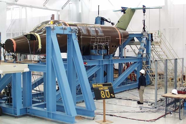
Test condition and data measurement
0 M=0.125,Re=1.6×10⁶
Static pressure measurement :
-2 Total 371 orifices (6 rows)
Force and moment measurement
-4 Flow visualization (Tuft method)
∆CD/CDturb[%]
-6
-8
-10
-12
Cruise
-14
-16
-3 -2 -1 0 1 2 3 4 5 6
Fig. 15. 1/3-scale low-speed wind tunnel test model.
Angle of attack [deg]
-6
Fig. 14. Drag reduction of NLF nose. -5 Experiment
Pressure coefficient
-4 VSAERO
-3
-2
3.5 High-Lift System -1
0
A 30-percent-chord, double-slotted flap, which 1
2
is deployed by a mechanical linkage, is
0.0 0.1 0.2 0.3 0.4 0.5 0.6 0.7 0.8 0.9 1.0 1.1
x/chorad
BL2800
employed to satisfy the stall-speed requirement
as well as the high-speed requirement. The
position of the vane with respect to the flap is
fixed. The shapes of the vane and the flap as
well as the gap and overlap were designed using
a two-dimensional, multielement, panel code M=0.125, Re=1.6×10⁶, α=6.49[deg]
(MCARFA, [10]) and a two-dimensional,
multielement, Euler code (MSES, [11]). The flap Fig. 16. Experimental and Theoretical Pressure
and vane shapes and positions were then tested Distribution of Flap.
on a 1/3-scale, half-span model in the Honda
3.0
Low-Speed Wind Tunnel (Fig. 15) and the Flap Up
6
results were compared with those from analysis Flap Take-off
Flap Landing
M=0.187,Re=1 X 10
2.5 Flap Up
(Fig.16) using a three-dimensional panel code Flap Take-off M=0.125,Re=1.6 X 10⁶
Flap Landing
[5], [6]. A test was also conducted using a
2.0
1/6-scale model in the Honda Low-Speed Wind
Lift coefficient
Tunnel. Examples of the lift curves obtained 1.5
from the 1/3-scale and 1/6-scale tests are shown
in Figure 17. The results for two Reynolds 1.0
numbers allowed the full-scale maximum lift
coefficient to be estimated more accurately 0.5
using an analytical method that incorporated the
pressure-difference rule [7]. The maximum lift 0.0
coefficient for the full-scale Reynolds number is
estimated to be higher than 2.5, which satisfies -0.5
-10 -5 0 5 10 15 20
the stall-speed requirement.
Angle of attack [deg]
3.6 Wind Tunnel Test Fig. 17. Lift curves with high lift device.
Low-speed wind-tunnel tests were conducted to Honda Low-Speed Wind Tunnel (Fig. 18(a))
obtain the aerodynamic characteristics of the and the University of Washington (UW)
aircraft. Two different wind tunnels, the low-speed wind tunnel (Fig. 18(b)) were used.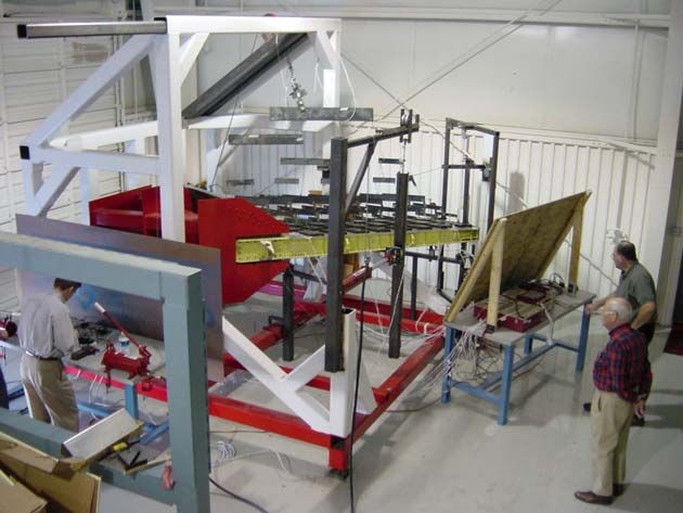
The stability derivatives obtained from these         conditions such as deep stall, spin, and
tests were used to evaluate the flight                one-engine out. A special feature of the HNAFS
characteristics. The tests were conducted to very     is the dynamic spin-chute model, including the
high angles of attack to obtain the post-stall aer-   inflation process, which was developed by the
odynamic characteristics of the aircraft, which       author. The deep-stall characteristics, which are
are critical for a T-tail configuration.              especially critical for a T-tail aircraft (e.g., [12]),
                                                      were carefully evaluated using the HNAFS. An
                                                      example of a deep-stall recovery simulation
                                                      using a spin chute is shown in Fig. 20. The time
                                                      histories of the aircraft angle of attack and the
                                                      elevator deflection are shown in Figure 20(a)
                                                      and the time history of the riser tension, in
                                                      Figure 20(b). This simulation shows that the
                                                      aircraft can be recovered from deep stall with a
                                                      spin chute under emergency conditions. The
                                                      simulation results were also used to design the
                                                      support structure for the spin chute.

          (a) Honda Low-speed wind tunnel

                                                             Fig. 19. Honda flight simulator (HNAFS).

           (b) UW low-speed wind tunnel               4 Aeroelasticity
            Fig. 18. 1/6-scale wind tunnel.           The flutter characteristics of the over-the-wing
                                                      engine-mount configuration were investigated
3.7 Flight Simulator                                  through extensive theoretical studies and
To evaluate the flying qualities of the aircraft, a   wind-tunnel tests. The location of the engine
flight simulator, called the Honda Nonlinear          mass and the stiffness of the pylon relative to
Aerodynamics Flight Simulator (HNAFS), was            that of the wing are important for wing-flutter
developed (Fig. 19). The simulator solves the         characteristics. Theoretical analysis using the
six-degree-of-freedom equations of motion in          ERIN code [13], which was developed by the
real time. The stability derivatives for the          author, was performed. Low-speed and
equations of motion were interpolated for each        transonic wind-tunnel flutter tests (at the
angle of attack, sideslip angle, control-surface      National Aeronautical Laboratory Transonic
deflection, etc., from an aerodynamic database        Flutter Wind Tunnel) were then conducted to
developed from the wind-tunnel test results.          validate the design (Fig. 21). The study shows
By interpolating within the database, the             that the symmetric flutter mode is more critical
HNAFS accurately simulates not only normal            than the anti-symmetric mode for the
flight conditions but also critical flight            over-the-wing engine-mount configuration.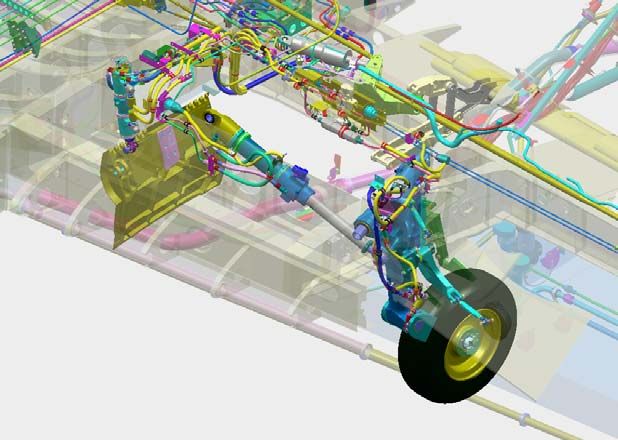
Deep stall simulation with spinchute deployment
Spinchute Open the engine-pylon vibration characteristics
deflection[deg]
70
70 influence the flutter characteristics. The flutter
60
60
speed is highest when the engine-pylon
angle(δe)
Angle of attack (AOA)
50
50
side-bending frequency is close to the uncouple
40
40
attack, Elevator
1st wing-torsion frequency (about 0.9 to 1.0
angle [deg]
30
30 AOA
Angle ofdeflection
20
20 times the uncouple 1st wing-torsion frequency).
10
10 δe The flutter speed is lowest when the
0 engine-pylon pitching frequency is about 1.25
Elevator
00 55 10
10 15
15 20
20 25
25 30
30 35
35 40
40 45
45
-10
-10
times the uncouple 1st wing-bending frequency
-20
-20
Time
Time [sec]
[sec] [13]. Based on these results, the wing stiffness
and mass distributions were designed to satisfy
(a) Time history of the aircraft AOA and δe. the flutter-clearance requirements.
Deep stall simulation with spinchute deployment
5 Structure
1800
1800
1600
1600 5.1 Wing
1400
1400
The wing is metal and constructed in three
Tension [kgf]
1200
1200
Tension [kgf]
1000
1000 sections: the left outboard wing, the center
800
800
600
600
section, and the right outboard wing (Fig. 22).
400
400 The torque box contains three spars, the ribs,
200
200 and the skin with integrated stringers forming an
00
2424 25
25 26
26 27
27 28
28 29
29 30
30 31
31 32
32 integral fuel tank. The upper skin is a machined,
Time [sec]
Time [sec]
integral panel to maintain the contour required
by laminar flow. By using integral, machined
(b) Time history of the riser tension. panels, the material can be distributed in the
Fig. 20. Deep stall simulation with spinchute deployment. most efficient manner and the number of parts is
minimized. The leading-edge structure and the
main torque-box structure are mated at about
13.5-percent chord to reduce the disturbance to
the laminar flow. The leading edge is equipped
with an anti-ice system that uses engine bleed
air ejected through a piccolo tube that directs
the hot air against the inside of the leading-edge
skin. The pylon structure is attached to a rein-
Carry-through
Engine-mount
Pylon
Fig. 21. Transonic wind tunnel flutter test at NAL Rear spar
transonic wind tunnel.
Front spar
Also the effects of the aerodynamic load and the Mid spar
interference due to the engine-nacelle installati-
on over the wing are small for this over-the
Fig. 22. Wing structure.
-wing engine-mount configuration. In addition,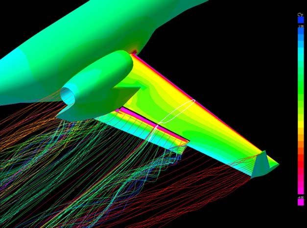
forced wing rib by four bolts. The main landing       adhesive properties. The outer surface of the
gear is also attached to the inboard end of the       outer acrylic ply and the inner surface of the
same reinforced rib to concentrate the heavy          inner acrylic ply are hard coated for abrasion
loads in one reinforced structure. The wing is        and chemical resistance. The windshield is
mounted under the fuselage by four links and          electrically heated for anti-ice protection. The
two thrust rods. The vertical loads are               windshield and its support structure were
transmitted to the front- and rear-fuselage main      designed to withstand the impact of a
frames by the links and the lateral loads are         four-pound bird strike at Vc (structural design
transmitted by the V-shaped links. The drag           speed) at sea level.
loads are transmitted to the fuselage by the two                                   Sandwich Panel
thrust rods.                                                                          Structure
                                                                     Stiffened Panel
5.2 Fuselage                                                            Structure
The fuselage is constructed entirely of graphite
composites. The material is a 350-degree-F cure        Sandwich Panel
                                                          Structure
epoxy prepreg reinforced by carbon fiber. (The
matrix is Cytec 5276-1 high-damage-tolerance,
epoxy resin and the reinforcement is TOHO
G30-500 high-strength, intermediate-modulus
fiber.) As shown in Figure 23, the cockpit as
well as the tail section is a honeycomb sandwich
construction to maintain the compound curves,
which are especially important for the
                                                                   Fig. 23. Fuselage structure.
laminar-flow nose. An integrally stiffened panel
structure is employed for the constant                5.3 Empennage
cross-section portion of the cabin, which
maximizes the cabin volume [14]. The frames           The empennage is a T-tail configuration. The
and stringers have identical dimensions in the        horizontal tail is a conventional, two-spar,
constant cabin section so the number of molds         aluminum structure. The fin is also a
for the frames and stringers are minimized. The       conventional, two-spar structure. The front spar
constant fuselage section can be easily extended      of the fin is, however, joined to the fuselage by
to satisfy future fuselage stretching. A feature of   a pin support and transmits only the forward,
the fuselage fabrication is that the sandwich         vertical, and lateral loads to the fuselage. The
panel and the stiffened panel are co-cured            rear spar is cantilever mounted to the
integrally in an autoclave to reduce weight and       rear-fuselage canted frame and transmits all
cost. It was a technical challenge to cure the        bending moments to the fuselage. The fin first
honeycomb sandwich structure under the                torsion frequency is very critical for the T-tail
pressure (85.3 psi) required for the stiffened        flutter mode and, therefore, relatively
panel but a new method called the                     heavy-gauge skin (0.04 in.) was employed to
“picture-frame stabilizing method” prevents           provide adequate torsional stiffness. Shear
core crushing.                                        buckling is not allowed up to the limit-load
                                                      condition      to   prevent    torsional-stiffness
The aircraft employs compound-curved                  reduction.
windshields to obtain better aerodynamic
characteristics. The windshields are two plies        6 Systems
(outer and inner) of stretched acrylic material
                                                      6.1 Landing Gear
with a polyurethane interlayer, which has
superior low-temperature ductility, a higher          The landing gear is a typical tricycle-type layout
allowable operating temperature, and higher           with a steerable nose wheel.
The nose gear is of the shock-absorber strut type.             mechanism. Under emergency conditions,
It is retracted forward by a drag-brace actuator               opening a dump valve and releasing the up-lock
(Fig. 24). The doors are mechanically linked                   mechanism by manual cable allow the free-fall
and open and close automatically with nose                     extension of the gear.
-gear movement. The drag-brace actuator has an
                                                                                                            Brake valve
internal down-lock mechanism. The nose gear is
equipped with a steer-by-wire system that is
electrically controlled and hydraulically actuat-
ed. There are two modes for the steering system:
parking mode, in which the steering-angle range
is +/-50 degrees, and normal mode, in which the
steering angle is limited to +/-10 degrees.                      In-board door
                                                                                                               Shock strut
Accumulator pressure provides emergency                             actuator
steering control should the hydraulic pump fail.                 Side brace actuator
                                                                               Wheel & Tire

  Drag brace actuator                                                              Main landing Gear door

  In-flight brake manifold                                                       Fig. 25. Main landing gear.
 Parking/emergency                                             The main gear is equipped with an anti-lock
    brake valve
                                                               braking system. A dynamometer test was
                                                               conducted to optimize the anti-lock system
                                                               control. Locked-wheel protection, touch-down
                                                               protection, and spin-up override are also
                                                               incorporated into the braking system.
                                                               Drop tests were conducted and the
                                                               shock-absorption characteristics evaluated. The
                                                               main landing gear and the nose gear were
   Up lock                                      Nose landing   dropped with a weight simulating the aircraft
                                                 gear door
                                                               weight (Fig. 26). The results showed that the
   Steering actuator                      Trunnion pin         efficiency of the oleo shock satisfies the
                                                               requirement.
             Landing light
                                            Wheel & Tire

                  Fig. 24. Nose landing gear.
The main landing gear is of the trailing-link
type and attached to the main wing (Fig. 25). A
side-brace actuator is used to extend and retract
the landing gear. The landing-gear doors consist
of three separate doors: inboard, middle, and
outboard. The inboard door is operated by an
independent hydraulic actuator and the middle
and outboard doors are linked to the main-gear
strut and open and close automatically with
main-gear movement. The wheel well is
completely covered by the doors and, therefore,
the tires are not exposed during cruise thus
reducing drag. The side-brace actuator is                                 Fig. 26. Nose landing gear drop test.
equipped with an internal down-lock
6.2 Flaps
A linkage mechanism is used for the flap system.
The flap system has two positions: 15.7
degrees down for takeoff and 50 degrees down
for landing, as shown in Figure 27. The flap is (a) Cruise position
deployed by two hydraulic actuators: one for
the right wing and the other for the left, each
installed at the wing root (Fig. 28). The right
and left flaps are mechanically interconnected to 15.7°
prevent a split condition.
A flap-mechanism fatigue test as well as a
(b) Take-off position
strength test were conducted. Simulated airloads
were applied by a whiffle tree pulled by a
hydraulic actuator. For the fatigue test, the
hydraulic actuator moves with flap movement
such that the loads are continuously applied as
in the flight condition. The flap mechanism 50°
satisfies the strength and fatigue-cycle
requirements determined for the flight-test (c) Landing position
program.
Fig. 27. Flap linkage mechanism.
6.3 Fuel
There are four fuel tanks in the aircraft: a Drive rod
right-wing integral tank, a left-wing integral Hydraulic
actuator
tank, a carry-through tank, and a rear-fuselage
bladder tank, as shown in Figure 29. The Interconnection
mechanism
aircraft is refueled from a single point located
on the right side of the rear fuselage. The fuel is
transferred from the carry-through tank to the
right- and left-wing integral tanks by transfer
pumps located in the carry-through tank. The
right-wing tank feeds the right engine and the
left-wing tank feeds the left engine through
collector tanks located under each pylon. The Fig. 28. Flap system.
primary pumps are ejector-type units and Single-point refuel port
Wing tip
electric boost pumps are used to provide fuel scavenge pump
and
refuel control panel
pressure for engine starting and cross feed. The Wing root
Fuselage
Fuel Transfer Management Unit (FTMU) scavenge pump
bladder tank
maintains the fuel level in the wing, which Firewall shutoff
Pressure
relieves the average wing-root bending moment relief valve valve
as much as 12 percent. An automatic cross-feed Wing
Boost pump
function is incorporated to correct fuel integral tank
imbalance between the left and right wings. A Transfer
pumps
Jet pump
total of 13 capacitance-type fuel probes--three
in the carry-through tank, two in the bladder Crossfeed
valve Collector
tank, and four in each wing tank--are provided. Carry-through tank tank
The fuel quantity can be measured within an
Fig. 29. Fuel system.Fig. 30. Cockpit. Fig. 31. Avionics system.
accuracy of 2 percent of the indicated fuel
quantity plus 1 percent of full scale during
sustained flight conditions anywhere in the
normal flight envelope.
6.4 Avionics
The aircraft employs a Garmin all-glass
flightdeck, which is a modular design having
open architecture. The cockpit is shown in
Figure 30. All information--from flight and
engine instrumentation to navigation, communi-
Fig. 32. Wing proof test.
cation, terrain and traffic data, etc.--is uniquely
integrated and digitally presented on the dual,
large-format, high-resolution Primary Flight
Displays (PFD) and the Multi-Function Display
(MFD). The PFD contains the airspeed indicator,
vertical-speed indicator, adjustable altimeter,
direction indicator, pitch and bank indicator
(artificial horizon), slip/skid indicator, dual
NAV/COM, etc. and the MFD contains the
EIDS (N1, ITT, N2, oil temperature and
pressure), fuel flow, fuel quantity, generator
current, GPS map, etc. The system diagram is
shown in Figure 31. This cockpit configuration Fig. 33. Fuselage proof test.
provides a high degree of integration for total of 26 computer-controlled actuators were
enhanced situational awareness, functionality, used to apply the simulated airloads, engine
ease of operation, redundancy, and flight safety. loads, landing-gear loads, etc. More than 600
channels of data (e.g., strain, displacement, and
7 Ground Tests
force) were measured and monitored at each test
7.1 Structural Proof Test for Wing and condition. A total of 10 load cases out of 870
Fuselage Structures were evaluated for the wing proof test (pylon
Proof tests were conducted to substantiate the vertical load, pylon side load, flap load, Vc
structural design of the wing (Fig. 32) and positive gust, Vc negative gust, right-hand and
fuselage (Fig. 33). The MTS Aero-90 test left-hand one-gear landing conditions, level
system (Fig. 34) was used to apply loads. A landing with spin-up load, side landing, andrudder maneuver). A total of 6 load cases out of empennage took the limit load without
1275 were evaluated for the fuselage test permanent deformation and the ultimate load
(pressurization load, positive-gust load, positive without any damage. Also the fin bending and
-gust load with pressurization, rudder-maneuver torsion-stiffness distribution were measured;
load, rudder-maneuver load with pressurization, there is no shear buckling up to the limit-load
and two-point landing load). Because the condition.
structures used for these tests were also used for
the flight-test program, the test loads were 7.3 Control-System Proof Test
limited to 80 percent of the limit loads. The The HondaJet has dual flight controls with
measured strain, displacement, and reaction- column-mounted control wheels and adjustable
force data were compared with those from a rudder pedals. A combination of cable and
finite-element analysis and the results were used push-pull rod mechanisms is used to actuate the
to evaluate the limit-load condition. elevator system and a cable mechanism is used
MDAC Subsystem
• 512 Multiplexed Data Acquisition(MDAC) channels
for the rudder and aileron systems. A proof test
894.50 Aero-90 System
• Two Consoles(256 Channels each)
was conducted to validate the elevator, rudder,
δ,ε
• 28 Load Control Channels
• Two test Stations
• 32 Integrated Data Acquisition(IDAC) channels
• 512 Multiplexed Data Acquisition(MDAC) channels
and aileron control-system designs (Fig. 36(a)).
• One Data Acquisition Test Station
MDAC Network
DSSC Subsystem
Control-system deflection under the limit load
User-Supplied • 28 Load Control Channels
Interlock • 32 Integrated Data Acquisition(IDAC) channels
System Hydraulic Components
One 454.30 Devices
Data Acquisition
Station control Panels User-Supplied 28 Series 243.XX
Load
Digital I/O Transducer Hydraulic Actuators
Devices
Interlock Servovalve
Synch Control Outpouts
Two 454.10/.20
Durability/Static Stroke
Station control Panels Transducer
Station
Hydraulic 293.11 Hydraulic Eight-Channel
Laboratory Control
Ethernet Service Manifold Hydraulic
Distribution Manifold
Hydraulic
Hose UPS
• 7KVA
System Workstations • 120 Vac/60Hz In
• 120 Vac/60Hz Out
• Three PC Computers
505.60 Hydraulic
• Two Laser Printers
Power Supply
•460 VAC/60Hz
Fig. 34. MTS Aero-90 system.
(a) Test set up
Fig. 35. Empennage proof test.
7.2 Static Test of Empennage Structure
A component strength test was conducted to
validate the structural design of the empennage
up to the ultimate load. The distributed loads
were applied to the structure through tension
pads and a whiffle tree (Fig. 35). A dummy rear (b) Hydraulic actuator
fuselage, which simulates the actual structure,
was used to evaluate the joint structure. The Fig. 36. Control system proof test.and breakout force were also measured. Loads Modular Signal Conditioner
with Bank Switching
Printer
were applied to the control surface by a PCB 440 series
Front End
hydraulic actuator (Fig. 36(b)) and the control Agilent E8403A
column or the rudder pedal was fixed by another
actuator. Control-system stiffness and friction Patch Panel
PCB 070C29
force were evaluated and the system mechanism Workstation
HP Visualize X
was adjusted to satisfy the requirement. Signal Conditioner
PCB 584A
Power Amplilfier
7.4 Ground Vibration Test (GVT) MB Dynamics
SS250VCF
A ground vibration test was conducted to Exciter Impedance Head Accelerometer
MB Dynamics Modal 50 PCB 288D01 PCB 356A22, 356A16, 352B67,etc
measure the vibration modes of the entire
aircraft and to establish the correlation with Fig. 38. Block diagram of GVT system.
those from the finite-element vibration analysis.
The aircraft was excited by six electrodynamic
shakers, which were attached to the aircraft by
flexible rods. The structural responses were
measured by a total of 383 piezoelectric
accelerometers attached to the aircraft (Fig. 37).
The ground vibration system is shown in Figure
38. The Maximum Entropy Method (MEM) was
used to identify the modal parameters. The
advantage of the MEM is that it provides higher
frequency resolution with smaller frame size
compared to classical FFT methods because the
frame size and the number of spectra lines are
independent of each other. The aircraft was
placed on specially designed air springs, which
decouple the rigid mode of the aircraft (Fig. 39).
The finite-element model was tuned by using
Fig. 39. Air spring.
the frequencies and mode shapes measured from
the ground vibration test to accurately determine 7. 5 Taxi Test
the aeroelastic characteristics of the aircraft.
Taxi tests were conducted to evaluate braking
and steering performance (Fig. 40). It is
important to evaluate the heat-sink capacity of
the braking system because a very large amount
of heat is generated during braking. An example
of the brake-temperature measurement for each
barking speed is shown in Figure 41. The
temperature is close to the estimates and the
result validates the brake heat-sink capacity.
The shimmy characteristics were also evaluated
and the measured damping satisfies the
requirement.
The acceleration and stopping distances were
measured and compared to those from analysis.
Fig. 37. Ground Vibration Test.
An example of acceleration and stopping-distan-ce measurement is shown in Figure 42. The 8 Flight Test
brake pressure applied for these tests were from After the ground tests were completed, the first
60 to 100-percent of the maximum pressure. flight was performed on December 3, 2003, at
The measured distances fall within the range of the Piedmont Triad International Airport in
analyses for friction coefficients from 0.30 to North Carolina. The flight-test program began
0.40. in January 2004 (Fig. 43).
The prototype is fully instrumented with a
data-acquisition system and a telemetry system
to maximize the efficiency of the flight-test
program (Fig. 44). More than 200 sensors,
which measure air data, attitude, acceleration,
control-surface deflection and control force, etc.,
are installed on the aircraft and all data are
transmitted to the ground. The data are analyzed
in real time on the ground [15].
In phase one of the flight-test program, in-flight
system-function tests such as landing-gear and
Fig. 40. High-speed taxi test.
flap operation were conducted. The tests were
700 performed under different flight conditions (e.g.,
Test condition
Rump-out Weight : 8404 (lbf)
airspeed, sideslip angle, etc.) and the function
600
MAC : 27.1%C was confirmed. Emergency gear operation was
Temperature Rise (degC)
Weather : Clear
500 also conducted to validate the extension of the
Taxi Test Results landing gear simulating electrical- and
400
Analysis hydraulic-system failure.
300
In phase two, stability-and-control and
200 performance tests were conducted. Static and
dynamic stability, such as short-period, phugoid,
100
and dutch-roll modes, were evaluated by
0 measuring the undamped natural frequencies
0 10 20 30 40 50 60 70 80 90 100 110 and damping ratios at various flight conditions.
Speed (kt) Cruise performance was evaluated by the
Fig. 41. Brake disk temperature rise vs taxi speed.Fig.
speed-power method. The results were
compared to analytical estimates and good
agreement was found.
ISA,H=926[ft]
µ BRK=0.30
µ BRK=0.35
µ BRK=0.40
Test Data
Distance
Engine Cut-off speed
Fig. 42. Accelerate-stop distance. Fig. 43. HondaJet flight test.Washington, June 2001.
Onboard System Ground System
Sensor Layout
Telemetry System
[Encorder]
[Auto Track Antenna]
[7] Valarezo, W. O., and Chin, V. D., ”Maximum Lift
Prediction for Multielement Wings” AIAA Paper
Strain: 62 Ch Elv. Disp PCU-816 050 2 4M
AMC-216
ELV Tab Disp
Accelerometer: 54 Ch Analog Card
E/G Data
ARC-429
PSCC-108
Arinc Card [Control Sys.]
ACU-21
92-0401, Jan. 1992.
Strain Card
Fuel Data TCC-116 [Receiver]
Avionics Data
RD Tab Disp
Temp. Card
RCB-2000
[PCM Decomitator]
[8] Eppler, Richard: Airfoil Design and Data.
Springer-Verlag (Berlin), 1990.
RD. Disp
Control Force VTS-100
Hydro. Sys. Data [Recorder]
Control Wheel
/Pedal Disp. Flap Data ATD-800
[Transmitter]
ST-810S
Honda
HondaFlight
Analysis
Data
Flight Data
System
Analysis System
[9] Holmes, Bruce J.; et al.: Manufacturing Tolerances
INS Data
3.0
EST.(Fuel FULL)
for Natural Laminar Flow Airframe Surfaces.
LEVEL3
LEVEL1
LEVEL2
Undamped Natural Frequency ω
Dutchroll EST.(Fuel HALF)
EST.(Fuel EMPTY)
Characteristics FLT#050 SEG13
2.5
Category B FLT#050 SEG14
Aileron Disp
FLT#050 SEG15
FLT#050 SEG16
TAT ECS Data [Onboard Antenna] ALT41000ft(DEMO) 2.0
N D[rad/sec]
850863, Soc. Automot. Eng., Apr. 1985.
1.5
6130 1.0
Air Data L/G Data 0.5
0.0
-0.10 -0.05 0.00 0.05 0.10 0.15
Dutchroll Dampingζ d
Longitudinal /Lateral Static Stability
Dutch Roll/Spiral mode analysis, etc.
[10] Morgan, Harry L.: High-Lift Flaps for Natural
Fig. 44. Telemetry block diagram. Laminar Flow Airfoils. Laminar Flow Aircraft
Certification, NASA CP-2413, 1986, pp. 31-65.
9 Concluding Remarks [11] Drela, M.: Design and Optimization Method for
Multi-Element Airfoils. AIAA Paper 93-0969, Feb.
Honda R&D is developing an advanced, 1993.
lightweight, business jet. The challenge of
[12] Fujino, M., “Aerodynamic and Aeroelastic Design
employing an unconventional configuration--an
of Experimental Aircraft MH02, ”
over-the-wing engine-mount configuration with DOT/FAA/CT-94/63 Proceedings of the 1994
natural-laminar-flow wing and fuselage nose, AIAA/FAA Joint Symposium on General Aviation
composite fuselage, etc.--has been met. Systems, May 24-25, 1994, pp. 435-459.
Extensive analyses and ground tests have been [13] Fujino, M.; et al.: Flutter Characteristics of an
conducted to validate the design. Flight tests are Over-the-Wing Engine Mount Business-Jet
being performed and the results are promising. Configuration. AIAA Paper 2003-1942, Apr. 2003.
More detailed performance tests as well as [14] Matsui, N.; and Sato, K.: Research Work of the
critical tests, such as flutter, will be conducted All-Composite Fuselage. Proceedings of 14th
in the next phases of the flight-test program. International Conference on Composite Materials,
July 2003.
10 References [15] Fujino, M.; et al.: Flight Test of the HondaJet. ICAS
2004-4.10.1, Proceedings of the 24th Congress of
[1] Fujino, M. and Kawamura, Y., “ Wave-Drag
the International Council of the Aeronautical
Characteristics of an Over-the-Wing Nacelle
Sciences, August 29 -September 3, 2004
Business-Jet Configuration. ” Journal of Aircraft,
Vol.40, No.6, November-December 2003,
pp1177-1184
11 Acknowledgements
[2] Fujino, M., et al., “Natural-Laminar-Airfoil The author wishes to thank Honda R&D for
Development for a Lightweight Business Jet,” permission to publish this paper and my
Journal of Aircraft, Vol. 40, No.4, July-August 2003, colleagues for their invaluable assistance. The
pp609-615 author also wishes to gratefully acknowledge
[3] Strash, D. J.; and Tidd, D. M.: MGAERO User's the cooperation of GARMIN International in the
Manual. Analytical Methods, Inc. Redmond, development of the avionics system and
Washington, 2002 Sumitomo Precision Products in the
[4] Tidd, D. M.; et al.: Application of an Efficient 3-D landing-gear development. Finally the author
Multi-Grid Euler Method to Complete Aircraft would like to thank Atlantic Aero for their
Configurations. 9th AIAA Applied Aerodynamics
Conference, AIAA Paper 91-3236, Baltimore, MD,
cooperation in this research.
Sep. 1991.
[5] Maskew, B.: Prediction of Subsonic Aerodynamic
Characteristics: A Case for Low-Order Panel
Methods. J. Aircraft, vol. 19, no. 2, Feb. 1982.
[6] Nathman, James K.: VSAERO User's Manual
Version 6.3. Analytical Methods, Inc. , Redmond,You can also read