BULB UNITS The compleTe soluTion for low heads
←
→
Page content transcription
If your browser does not render page correctly, please read the page content below
BULB UNITS
The compleTe soluTion for low heads

                               power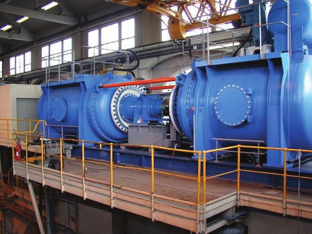
model scale bulb runner

Alstom bulb units
for BeST performANce
Alstom Hydro is the number one global              The name “bulb” comes from the shape of the     and civil works requirements of up to 25%.
provider of clean power solutions accounting       upstream watertight casing which contains a     There are hundreds of alstom bulb units now
for around 25% of the world’s installed hydro      generator located on a horizontal axis. units   in operation around the world with more than
base and offers the world’s most compre-           are submerged in the water passage and, as      35 large units commissioned in china alone
hensive range of hydropower generation             the turbines are usually double regulated,      during the last ten years.
facilities and equipment.                          are able to handle significant discharge
                                                   variations.                                     The company has been an ardent pioneer in
it is not surprising then that alstom bulb units                                                   the development of bulb units introducing
provide the most efficient solution when           The straight water passage in the draft tube    many outstanding innovations in size, design
faced with very low and low heads up to 30m.       improves the hydraulic behaviour of the unit,   and operational efficiency and will continue
Bulb units have now virtually replaced Kaplan      and also results in a low submergence. This,    the research and development programme to
turbines for low head situations.                  in turn, allows for a reduction in size, cost   extend the application range. Both standard-
                                                                                                   ised and customised solutions are offered.
                                                                                                   Specific technologies have been developed to
                                                                                                   adapt to customers’ needs and site surround-
                                                                                                   ings such as the use of mobile or fixed guide
                                                                                                   vanes and runner blades, shaft lines on 2 or
                                                                                                   3 bearings, and pit turbine technology with a
                                                                                                   speed increaser.

                                                                                                    Alstom has gained outstanding knowledge
                                                                                                    and experience in design, manufacturing,
                                                                                                    installation, commissioning and manage-
                                                                                                    ment of complex bulb projects in a vast range
                                                                                                    of environmental conditions, making Alstom
                                                                                                    bulb units without doubt the world’s most
                                                                                                    reliable solution.

alstom bulb units application range

2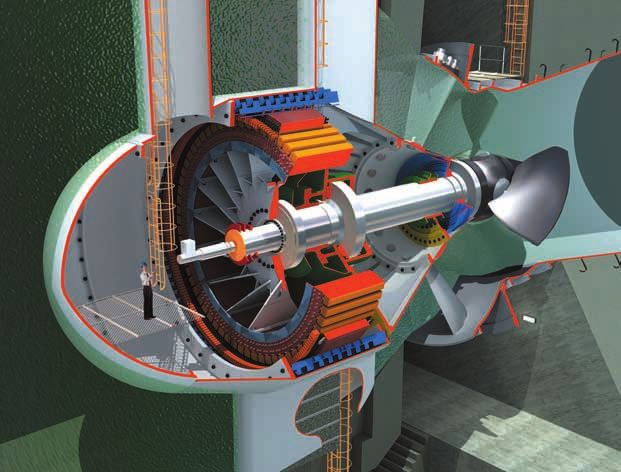
Customer value-driven
                                                  GLoBAL opTImISATIoN
General design of a bulb unit

coNSTANT r&D To meeT                              an alstom bulb unit delivers maximum              The system comprises three major parts:
eNvIroNmeNTAL coNcerNS                            customer value and return on investment.          • Centralog provides the operator control inter-
Alstom is also committed to helping custom-       equipment investigation and design is carried       face and control room environment with
ers balance commercial objectives with            out by experienced interdisciplinary teams          high availability and high performances
environmental and social responsibilities.        as part of the total system optimisation.         • Controbloc automation cells execute the
                                                  alstom’s global geographical coverage and           control and protection functions of the
increasing environmental concerns are taken       the largest installed base allow the feedback       machines and connect to the process.
into account resulting in fish-friendly turb-     of experience to be taken into account              The use of fieldbuses allows geographical
ines. in bulb turbines fewer but longer blades    for each new project, whilst its local pre-         distribution of the equipment
decrease the fish mortality, while maintaining    sence guarantees a perfect understanding of       • Controcad provides a set of advanced engin-
efficiency levels.                                regional variations.                                eering tools both for the design office and
                                                                                                      the on-site high quality documentation
 oil-free operations that prevent the pollution   Thanks to a global r&d organisation, the
 of rivers have also been developed, resulting    main design parameters are defined by             alspa p320® provides many features and
 for example in runners lubricated by water in    hydraulic, mechanical and electrical engineers    benefits for the plant owner and operator
 many bulb units.                                 working in close collaboration. This leads to     including:
                                                  improved results for the bulb outer dimension     • Hi-tech technologies: object oriented
pLANT INTeGrATor                                  by considering and evaluating factors such           engineering, internet, fieldbus
in the field of power generation, alstom is       as productivity, global efficiency, civil work,   • Intuitive, user friendly operator interface
the plant integrator specialist, combining        investment and reliability of the power-          • Modular design concept
skills in component design, auxiliary systems,    generating unit.                                  • Adaptable multifunction controllers
construction and plant optimisation. alstom’s                                                       • Distributed control architecture
answer to the market’s growing need for turn-      the ability to offer the world’s broadest        • Open system architecture based on inter-
key solutions is a unique combination of           scope of power generation equipment and             national standards
in-house core components and customised            systems enables Alstom to deliver complete       • High performance, communication net-
plant solutions based on the integration of        optimised solutions, from turbines and gen-         works
complementary packages.                            erators to control systems and balance of        • Integrated comprehensive Plant Manage-
                                                   plant, including a full turnkey service.            ment system (integration of alstom expert
 this original combination creates more value                                                          software)
 for customers than the simple addition of        The alstom product range covers complete
 individual packages by optimising:               electromechanical and hydro-mechanical            Hydroprocess
 • Investment costs                               equipment for new hydropower plants, as well      centralised plant and dam management
 • Lead times                                     as for the rehabilitation of existing plants.     software are embedded in the central super-
 • Performance and availability                                                                     vision system, providing a set of functions
 • Retrofit solutions                             DISTrIBUTeD coNTroL SYSTem                        managing the active and reactive power
 • Plant life cycle                               alstom has a proven worldwide experience in       production of the power plant as well as the
                                                  control systems for the power industry. over      dam and the reservoir water level.
                                                  500 thermal, hydraulic and nuclear units
                                                  have been equipped in 25 years.                    Alstom’s engineering depar tment has
                                                                                                     acquired a vast experience in control and
                                                  Taking advantage of its in-depth knowledge         instrumentation systems for all kinds of
                                                  of the hydro power plant processes, alstom         hydro power plants. its expertise in providing
                                                  has developed a comprehensive control and          tailor made solutions guarantees optimal
                                                  instrumentation system, providing modern           plant control implementation.
                                                  operating control for hydro power plants.

                                                   Alstom’s automation product, commonly
                                                   known as AL SPA P320® system, is the
                                                   most suitable system to control and monitor
nina power station (china)                         Alstom hydro power plant.

                                                                                                                                                  3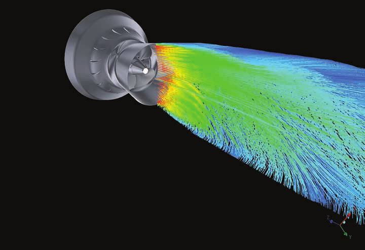
HYDrAULIc DeSIGN
                                                  state-of-the-art facilities and tools
                                                  for optimised designs

                                                                                                   Downstream velocity field

Alstom has developed advanced technology          THeoreTIcAL INveSTIGATIoN AND
to optimise all hydraulic parameters. This        ScIeNTIfIc cALcULATIoNS
ensures that turbine designs perfectly match
the targeted characteristics of a given pro-       Alstom has developed many software codes
ject, while taking into account any necessary      to perfect shape design, from classical ones
constraints.                                       to those based on full 3D surface generation
                                                   using global optimisation algorithms. these
during the hydraulic design phase, unit            permit the exploration of new design families
p er f or mance s ar e pr e dic t e d t hr ough    and allow the best shapes to be verified on a
theoretical investigation and experimental         test rig.
developments.
                                                  during the design process, deep numerical
Each component of the turbine is finely tuned,    investigations using the latest cfd codes
from intake, stay vanes and distributor, to       (computation fluid dynamics) are carried
runner and draft tube. alstom’s objective is      out. These simulate the flow in the turbine
to optimise efficiencies, minimise dimensions     over the whole of the expected operating
and reduce downstream head losses.                range and help to determine the best adapted
                                                  turbine shape.

                                                  They allow the accurate determination of all
                                                  hydraulic parameters, such as load analysis,
                                                  efficiency and cavitation behaviour.             Turbine pressure field

4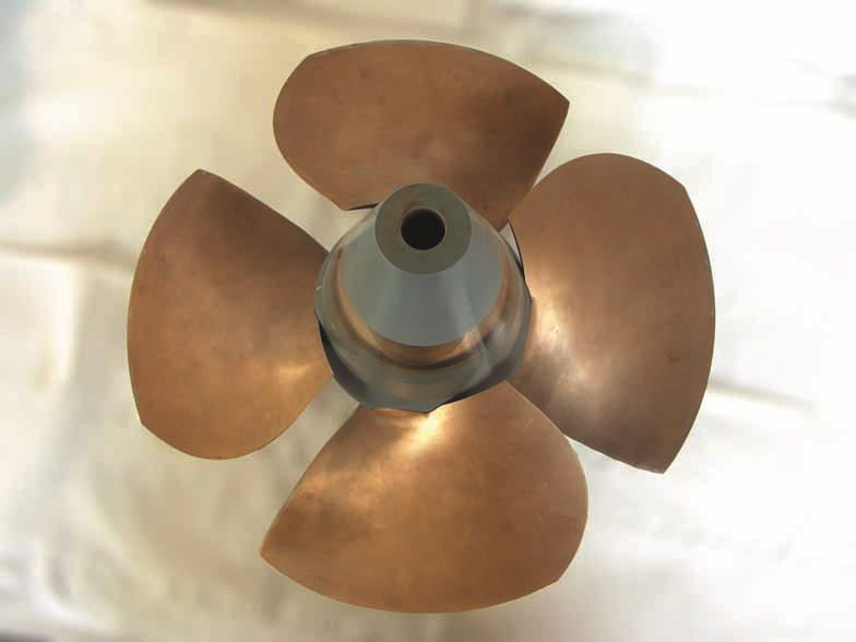
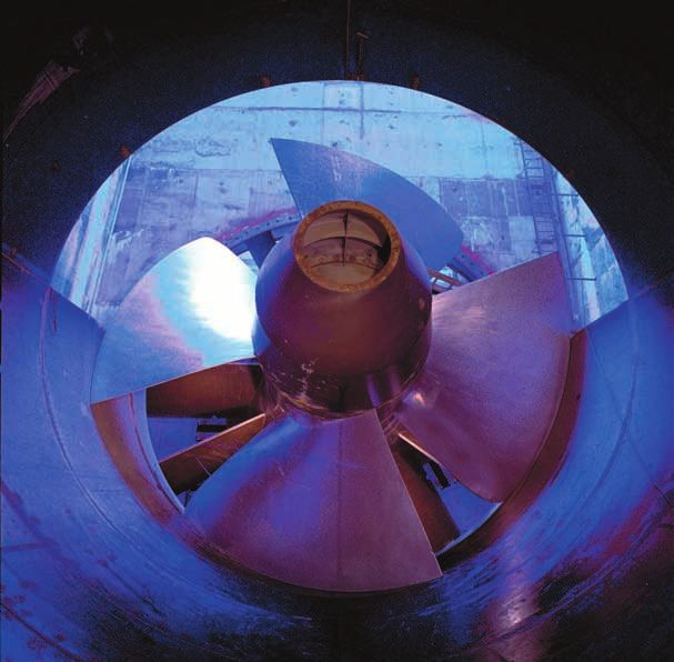
dedicated bulb test rig

moDeL AND SITe TeSTING
Once a design has been defined theoretically,
its performance is validated by model tests in
                                                    GoverNING system
an alstom Global Technology centre.                 Alstom has more than 100 years of exper-        These systems fulfil various functions:
                                                    ience in the expert analysis and production     • Speed governing in isolated or inter-
Two recent test rigs, one of which has been         of speed governing products.                      connected networks
in operation since 2003, are used for bulb                                                          • Fast unit start and speed stability control
turbines, with up-to-date calibration tools         The speed governor is the brain of hydraulic      under no-load operating conditions
and automated acquisition systems.                  turbines. It fulfils all the requirements and   • Automatic unit/network synchronisation
                                                    needs of hydraulic turbine applications.          through runner blades, guide vanes or
T hese advanced facilities permit ver y                                                               downstream gate control
accurate measurements that are also a key                                                           • Flow or load regulation
tool for performance improvement and act as                                                         • Efficiency optimisation with respect to
a further complete check of turbine behav-                                                            head and load
iour, including efficiency, output, cavitation,                                                     • Autonomous sluicing operation at variable
runaway and torque on blades.                                                                         or steady flows
once all the investigations are completed, the                                                      • Blade/guide vane cam relationship
full scale turbine is manufactured and tested
on site if required. it is due to this continuous                                                   neYrpic® T.slG (Turbine speed load
process of research, design and testing that                                                        Governor) is the latest product developed by
alstom remains the world leader in innovative                                                       alstom. it is interfaced with an automated
bulb unit technology.                               T.slG governor with actuators                   system to ensure flexibility of use.

                                                                                                    designed to operate in the most extreme
                                                                                                    environments, the main benefits are its
                                                                                                    high level of adaptability, robustness and
                                                                                                    reliability.

universal turbine test rig

                                                                                                                                               5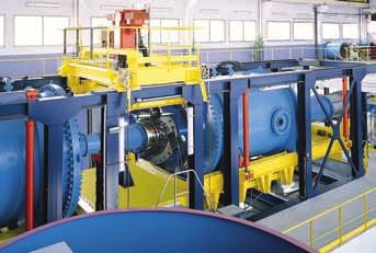
MechAnIcAL DeSIgn
WHAT IS DIffereNT ABoUT ALSTom HYDro peLToN TUrBINeS?

         Safety and reliability
To ensure the safety and reliability of all units,   STAY rING                                         DISTrIBUTor
Alstom carries out a continuous mechanical           The stay ring is the sole support structure of    The conical distributor comprises 16 moving
r&D programme on all turbine parts.                  the unit. This provides many advantages:          guide vanes. They are guided on self lubricat-
                                                     • Weights and vertical loads are evenly           ing bearings and controlled by an operating
during mechanical design, the complete                 distributed in civil engineering structures     ring.
bulb structure is analysed by finite-element         • A xial forces carried to the anchor are
calculations covering stresses, deflections            limited to hydraulic loads                      To ensure continuous operational safety, the
and eigenfrequencies to check the static and         • Civil works are simplified                      distributor can be closed under both normal
dynamic behaviour of the entire unit.                                                                  and runaway conditions.
                                                     The two vertical arms of the stay ring are
                                                     hollow for generator bus bar outlet and piping.   for units with a downstream gate, the
                                                     This also allows easy access to the shaft seal    operating ring is actuated by two push-pull
                                                     for adjustments.                                  servomotors. shear pins are used as safety
                                                                                                       devices for the guide vanes.

                                                                                                       in the case of no downstream gate being
                                                                                                       installed, the servomotors use a counter
                                                                                                       weight to close the guide vanes safely.
                                                                                                       a self-resetting device is then used instead of
                                                                                                       a shear pin, to avoid the unit shutting down in
                                                                                                       the event of a guide vane jamming.

finite-element dynamic analysis

6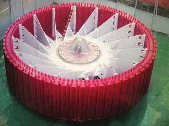
erection time
                                                                                                       opTImISATIoN
rUNNerS Up To 9m DIAmeTer                           Thrust and counter-thrust bearing pads are         since the draft tube is embedded into concrete
runner design is one of the most important          designed to handle the axial hydraulic force.      as a first stage, the stay ring is set into the
tasks that alstom carries out when optimising       The counter-thrust bearing is stressed for a       civil engineering structures. Then the shop-
a unit for each project.                            few seconds in case of load rejection.             assembled distributor is fitted. The shaft,
                                                    The thrust bearing pads are supported by           pre-fitted with bearings, thrust bearing and
Blades can be directional, driven by a moving       membranes to ensure even load distribution,        counter-thrust bearing, is then inserted into
servomotor cylinder located inside the runner       independent of the shaft movements.                the assembly.
hub.
                                                    Bearing and thrust-bearing lubrication is          The shaft line is adjusted on site so that the
Runner hubs are normally filled with oil, but       carried out by gravity from an oil tank located    generator rotor and the turbine runner are
for environmentally sensitive locations, water      above the unit. This very simple process has       centred on the theoretical axis of the unit.
may be used as a lubricant.                         proven to be extremely reliable.

SHAfT LINe AND BeArINGS                             DoWNSTreAm GATe
                                                    a draft tube gate provides a reliable protective
 two radial bearings ensure the dynamic             system for bulb units.
 stability of the horizontal shaft line during
 operation.                                         The downstream gate is sufficiently remote
                                                    from the runner to have a limited effect upon
The combined axial-radial bearing is located        the design of the draft tube. its shape is
next to the centre of gravity of the generator      designed to avoid the accumulation of solid
rotor. it carries the weight of the rotor and the   deposits on the side grooves.
force of the unbalanced magnetic pull when
the machine is in normal operation.                 downstream gate functions are:
                                                    • Protection against runaway conditions
in case of double rotor earth fault, huge           • Downstream isolation during unit dewater-        runner erection
rotating forces act not only on the bearing,          ing
but also on the bearing and bracket supports.       • Sluice operation                                 an initial adjustment is made by eccentration
The axial bearing is designed for steady-state                                                         of the guide bearings following the shaft line
conditions of the turbine and also for dynamic      for units without control devices (fixed           calculation. The final process is completed on
hydraulic transients.                               distributor), the downstream gate also             site, centring the stator on the rotor and the
                                                    initiates unit starting, coupling, progressive     runner chamber on runner blades.
The turbine guide bearing is supported by           loading and shutdown.
a semicircular plate that allows it to follow                                                          The following operations are carried out
the shaft movements. Generator and turbine                                                             simultaneously:
bearings are both shell type bearings.                                                                 • Erection of rotor, stator and bulb nose in
                                                                                                         the upstream pit
                                                                                                       • Erection of the runner hub, blades, turbine
                                                                                                         cone and runner discharge in the down-
                                                                                                         stream pit
                                                                                                       • Erection of accessories

Bulb shaft line and bearings assembly

                                                                                                                                                    7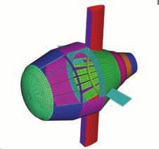
ADvAnceD
                                                           GeNerATor DeSIGN

Alstom design concepts ensure reliability in               roTor                                                   oblique elements are used in the rotor spider
all operating circumstances taking account                                                                         to provide optimum resilience regarding
of the bulb unit’s sensitivity to instability                With the introduction of oblique elements             thermal expansion, centrifugal force and
and vibrations due to the horizontal position                for hydroelectric generators two decades              operational torques.
of the generator. They have been developed                   a g o , A l s t o m l a un c h e d a n e w e r a in
to handle conditions such as roundness and                   large generator design, offering outstanding            Compared to classical designs with radial
air gap concentricity, and have been success-                mechanical performance.                                 arms, oblique arms offer many advantages.
fully applied in bulb units up to 60 mvA.                                                                            machine torque only stresses the arms
                                                           oblique arms connect two concentric annular               in the tensile direction while oblique arms
                                                           parts, the rotor hub and the rotor rim, allowing          absorb rim expansion due to centrifugal force
STATor DeSIGN                                              them to turn in relation to each other.                   and thermal dilatation by allowing rotation
alstom stator designs incorporate special                                                                            of the rim in relation to the hub. Alstom
V- s h ap e d e l e m e n t s w i t h s i gni f i c an t   The application of oblique elements on the                rotor design also permits stacked rotor rims
operational advantages. They guarantee the                 rotor provides improved radial precision and              without shrink fit to the rotor spider.
necessary stiffness required of the structure,             a uniform air gap under all load conditions.
with less radial height compared with trad-
itional design concepts. They also ensure the
necessary space between stator core and
casing required for efficient air circulation
through the cooling slots.

The alstom stator key bar design, in combina-
tion with the spring effect of V-elements and
stator core pressing system, provides vital
protection against stator core buckling.

                                                           Bulb generator rotor with oblique arms

8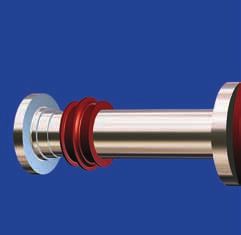
vpI INSULATIoN SYSTem
The reliabilit y of the stator winding is
                                               The uniform Vpi production process ensures
                                               a high insulation quality with the following       Field
determined primarily by the quality of its
insulation. a generator is heavily stressed
thermally, electrically and mechanically
                                               properties:
                                               • The requirements of temperature class F
                                                 are met
                                                                                                  excITATIoN
during operation. This makes the heaviest      • High dielectric strength and voltage en-           A reliable excitation system is the key
demands on insulation.                           durance values with low loss factors               to trouble-free generator operation. It
                                               • Proven system for all types of electrical          ensures fast and efficient reactive power
  the MIcADuR® vacuum pressure impreg-           machines up to 30 kV                               and voltage control, and the best possible
  nation system (vPI) has been used by         • Excellent corona-resistance                        generator performance overall.
  Alstom for more than 40 years.               • Very good resistance to oil, water and other
  t he s y s t em has b e en cont inuousl y      coolants                                         alstom automatic voltage regulators and
  researched and further developed and has     • Excellent mechanical properties                  excitation systems have been produced for
  produced excellent results on all machines                                                      more than 35 years with the installation of
  even under severe conditions.                other Vpi insulation systems can also be           2,850 systems controlling 315,000 mVa in
                                               provided.                                          130 countries.

                                               AIr cooLING SYSTem                                 To guarantee optimal results, all alstom gen-
                                               The closed air ventilation system is designed      erators come with a high quality excitation
                                               for safe operation at maximum output and           system as a standard.
                                               maximum river water temperature.
                                               To guarantee high unit availability, the cooling   for medium and high speed machines,
                                               system is generally installed with a redundant     brushless excitation systems are provided.
                                               complete cooling device.                           synchronous machines are supplied with
                                                                                                  rotating diodes. This supplies dc-current to
                                               in order to provide maximum value to               the rotor without any brushes or slip rings,
                                               customers, alstom offers integrated solutions      which are commonly subject to wear and tear.
                                               in combination with the secondary cooling          Both solutions are equipped with the latest
                                               circuit. Thanks to its vast experience in bulb     automatic voltage regulation (p 320 aVr)
                                               generator design, alstom always delivers           technology.
                                               maintenance-free and reliable solutions.
wedging of the stator bar in stator core                                                          all alstom static excitation systems in-
                                                                                                  corporate state-of-the-art technology and
                                                                                                  the required redundancy provision.

                                                                                                                                             9
WorLDWIDe
Project highlights
la rance, france 1966
cANADA
Bromptonville 1997 - 1 unit, 11MW, run. dia.: 3.75m.
Saint Lambert 1995 - 1 unit, 6.2MW, run. dia.: 4.50m.
USA
Worumbo 1989 - 2 units, 10 MW, run. dia.: 4.25m.
Greenup 1982 - 3 units, 25 MW, run. dia.: 6.10m.
rock Island 1978 - 8 units, 58 MW, run. dia.: 7.40m.
BrAzIL
ourhinos 2004 - 3 units, 15MW, run. dia.: 4.25m.
canoas 1999 - 6 units, 27MW, run. dia.: 4.70m.
Igarapava 1999 - 5 units, gen.: 44 MvA.
AUSTrIA
pfarrwerfen 1995 - 2 units, gen.: 11 MvA.
croATIA
cakovec 1982 - 2 units, 42 MW, run. dia.: 5.40m.
frANce
Saint egreve 1990 - 2 units, 23.4 MW, run. dia.:
5.60m.
Argentat 1989 - 1 unit, 17 MW, run. dia.: 4.10m.
Sault Brenaz 1986 - 2 units, 23 MW, run. dia.: 6.25m.
chautagne/Belley 1980 - 4 units, 46 MW, run. dia.:
6.40m.
caderousse 1975 - 6 units, 32 MW, run. dia.: 6.90m.
Sauveterre 1973 - 2 units, 33 MW, run. dia.: 6.90m.
La rance 1966 - 24 units, 10 MW, run. dia.: 5.35m.
GermANY
Heidelberg 1997 - 2 units, 2 MW, run. dia.: 3.35m.
Guttenbach 1992 - 1 unit, 3 MW, run. dia.: 3.16m.
HUNGArY
Tisza 1973 - 4 units, 7 MW, run. dia.: 4.30m. LUxemBoUrG
Schengen 1995 - 2 units, 2.4 MW, run. dia.: 3.50m.
porTUGAL
crestuma 1987 - 3 units, 43 MW, run. dia.: 6.80m.
TUrkeY
Seyan 2 1992 - 3 units, 3 MW, run. dia.: 3.50m.
SWITzerLAND
rheinfelden 2007 - 4 units, gen.: 25 MvA.
ruppoldingen 2000 - 2 units, gen.: 12 MvA.
10rock island, usa 1976 wu Jin Xia, china 2005
Alstom has equipped more than 250 bulb
units in the world for a total output of
approximately 5,000 mW.
SoUTH koreA
Nam Gang 2000 - 2 units, 7 MW, run. dia.: 3.00m.
paldang 1999 - 4 units, 31.5 MW, run. dia.: 5.20m.
cHINA
chang zhou 20 07 - 3 units, 42.9 MW, run. dia.:
7.50m.
Tong Wan 2007 - 4 units, 46.2 MW, run. dia.: 7.10m.
Qiao Gong 2007 - 4 units, 58.5 MW, run. dia.: 7.45m.
Wu Jin xia 2007 - 4 units, 36.1 MW, run. dia.: 7.00m.
zhi Gang La Ka 2005 - 4 units, 39.0 MW, run. dia.:
6.10m.
Ni Na 2003 - 4 units, 41.0 MW, run. dia.: 6.00m.
Hongjiang 2003 - 5 units, gen.: 47 MvA.
Gong chuan 20 01 - 2 units, 22.2 MW, run. dia.:
5.50m.
Sha xian 1999 - 3 units, 16.5 MW, run. dia.: 4.90m.
INDIA
Sone Link canal 1986 - 6 units, 2 MW, run. dia.:
3.22m.
11pWS/BproB/BLBNTS09/eng/HYD/01.09/fr/6786 © ALSTom 2009. all rights reserved. information contained in this document is provided without liability for information purposes only and is subject to change without notice. no representation or warranty is given or to be implied as to the
completeness of information or fitness for any particular purpose. Reproduction, use or disclosure to third parties, without express written authority, is strictly prohibited. - Photo credits: Alstom 2009 - Design & Layout: www.kineka.com.
ALSTom Hydro
4, avenue andré malraux
www.power.alstom.com/hydro
92309 levallois perret cedex - franceYou can also read