HOME AUTOMATION USING ARDUINO WIFI MODULE ESP8266 - Core
←
→
Page content transcription
If your browser does not render page correctly, please read the page content below

HOME AUTOMATION USING ARDUINO
      WIFI MODULE ESP8266

                  A PROJECT REPORT

                       Submitted by
                    ILYAS BAIG
                 CHIKTAY MUZAMIL
                 SALAHUDDIN DALVI

   in partial fulfillment for the award of the degree of

                          B.E

                           IN

        ELECTRONICS & TELECOMMUNICATION

                           At

              ANJUMAN-I-ISLAM’S
     KALSEKAR TECHNICAL CAMPUS
                      PANVEL
                      2015-2016
Project Report Approval for B.E

This project report entitled HOME AUTOMATION USING ARDUINO WIFI MODULE

ESP8266 by Ilyas Baig Chiktay Muzamil Salahuddin Dalvi is approved for
the degree of Bachelor in Engineering.

 Examiners:

1._______________________________.

2._______________________________.

Supervisor(s):
____________________________________
Asst. Prof. BANDANAWAZ M. KOTIYAL

H.O.D (EXTC):
___________________________
Asst. Prof. MUJIB A. TAMBOLI

Date:
Place

                                         1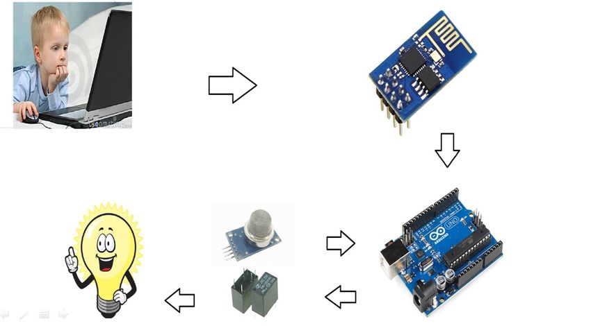
DECLARATION

We hereby declare that the project entitled "HOME         AUTOMATION USING
ARDUINO WIFI MODULE ESP8266" submitted for the B.E. Degree is Our
original work and the project has not formed the basis for the award of any
degree, associate ship, fellowship or any other similar titles.

Signature of the Student

Ilyas Baig

Chiktay Muzamil

                                      2
Salahuddin Dalvi

Place: New Panvel

                            ACKNOWLEDGEMENT

      Before we get into thick of things I would like to add few
heartfelt words for the people who are part of our team as they have been
unending contribution right from the start of construction of the report.

      Apart from the team I am indebted to the numbers of persons who
have provided helpful and constructive guidance in the draft of material.

      I acknowledge with deep sense of gratitude towards the
encouragement In the form of substantial assistance provided each and
every member of my team.

      I would like to extend my sincere thanks to our guide

                                          Asst.Prof. Banda Nawaz

For providing us the required technical guidance in the process of
preparing this report.

                                      3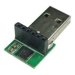
ABSTRACT

This project presents a design and prototype implementation of new home
automation system that uses WiFi technology as a network infrastructure
connecting its parts. The proposed system consists of two main components; the
first part is the server (web server), which presents system core that
manages, controls, and monitors users’ home.

Users and system administrator can locally (LAN) or remotely (internet)
manage and control system code. Second part is hardware interface module,
which   provides   appropriate   interface   to   sensors   and   actuator   of   home
automation system.

Unlike most of available home automation system in the market the proposed
system is scalable that one server can manage many hardware interface modules

                                         4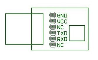
as long as it exists on WiFi network coverage. System supports a wide range of
home automation devices like power management components, and security
components.

The proposed system is better from the scalability and flexibility point of
view than the commercially available home automation systems.

                                      5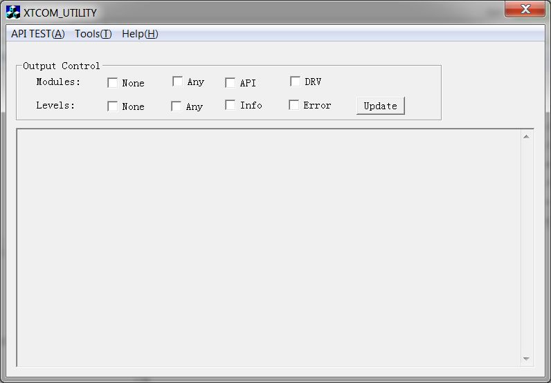
TABLE OF CONTENTS

                     Contents
APPROVAL………………………………………………………………………..1
DECLARATION………………………………………………………………….2

ACKNOWLEDGEMENT ………………………………………………………. 3

ABSTRACT………………………………………………………………………4

CHAPTER NO.01………………………………………………………………..

INTRODUCTION………………………………………………………………...6

CHAPTER NO.02……………………………………………………………….

OBJECTIVE OF THE PROJECT………………………………………………...8

CHAPTER NO.03…………………………………………………………………

LITERATURE SURVEY……..…………………………………………………..10

CHAPTER NO.04…………………………………………………………………

SCOPE OF THE PROJECT…………………………………………..…………13

CHAPTER NO.05…………………………………………………………………

METHODOLOGY …………...………………………………………...…….….15

CHAPTER NO.06…………………………………………………………………

HARDWARE…………………………………………………………………….17

CHAPTER NO.07…………………………………………………………………

SOFTWARE….……………………….….……………………………………...34

CHAPTER NO.08……………………………………………………………….

REFRENCES & BIBLIOGRAPHY……………………………..………………46

                         6
CHAPTER NO.01
INTRODUCTION
7INTRODUCTION
The project aims at designing an advanced home automation system using normal
web server and Wi-Fi technology. The devices can be switched ON/OFF and
sensors can be read using a Personal Computer (PC) through Wi-Fi.
Automation is the most frequently spelled term in the field of electronics.
The hunger for automation brought many revolutions in the existing
technologies. These had greater importance than any other technologies due to
its user-friendly nature. These can be used as a replacement of the existing
switches in home which produces sparks and also results in fire accidents in
few situations. Considering the advantages of Wi-Fi an advanced automation
system was developed to control the appliances in the house.
Wi-Fi (Short for Wireless Fidelity) is a wireless technology that uses radio
frequency to transmit data through the air. Wi-Fi has initial speeds of 1mbps
to 2mbps. Wi-Fi transmits data in the frequency band of 2.4 GHz. It implements
the concept of frequency division multiplexing technology. Range of Wi-Fi
technology is 40-300 feet.
The controlling device for the automation in the project is a Arduino UNO. The
data sent from PC over Wi-Fi will be received by Wi-Fi module connected to
8Arduino UNO. Arduino UNO reads the data and decides the switching action of
electrical devices connected to it through Relays.
9CHAPTER NO.02
OBJECTIVE OF PROJECT
The goal of this project is to develop a home automation system that
gives the user complete control over all remotely controllable aspects
of his or her home.
10 The automation system will have the ability to be controlled from a
central host PC, the Internet, and also remotely accessed via a Pocket
PC with a Windows Mobile based application.
The System will also sense the Accidental Gas leakage , water level and
will notify the user by SMS.
11CHAPTER NO.03
LITERATURE SURVEY
Literature survey:
Review of Related Literature:
When people think about home automation, most of them may imagine living
in a smart home: One remote controller for every household appliance, cooking
12the rice automatically, starting air conditioner automatically, heating water
for bath automatically and shading the window automatically when night coming.
To some extent home automation equals to smart home. They both bring out smart
living condition and make our life more convenient and fast.
Review of Foreign Studies:
In their paper, Tan, Lee and Soh (2002) proposed the development of an
Internet-based system to allow monitoring of important process variables from
a distributed control system (DCS). This paper proposes hardware and software
design considerations which enable the user to access the process variables on
the DCS, remotely and effectively
Potamitis, Georgila, Fakotakis, and Kokkinakis, G. (2003) suggested the use of
speech to interact remotely with the home appliances to perform a particular
action on behalf of the user. The approach is inclined for people with
disability to perform real-life operations at home by directing appliances
through speech. Voice separation strategy is selected to take appropriate
decision by speech recognition
In the year 2006 , S. M. Anamul Haque,S. M. Kamruzzaman and Md. Ashraful Islam
proposed a system entitled “A System for Smart-Home Control of Appliances
Based on Time and Speech Interaction” that controls the home appliances using
the personal computer. This system is developed by using the Visual Basic 6.0
as programming language and Microsoft voice engine tools for speech
recognition purpose. Appliances can be either controlled by timer or by voice
command.
13Ciubotaru-Petrescu, Chiciudean, Cioarga, and Stanescu (2006) present a design
and implementation of SMS based control for monitoring systems. The paper has
three modules involving sensing unit for monitoring the complex applications.
A processing unit, that is microcontroller and a communication module that
uses GPRS modem or cell phone via serial port RS-232. The SMS is used for
status reporting such as power failure.
Jawarkar, Ahmed, Ladhake, and Thakare (2008) propose remote monitoring through
mobile phone involving the use of spoken commands. The spoken commands are
generated and sent in the form of text SMS to the control system and then the
microcontroller on the basis of SMS takes a decision of a particular task.
Prof. Era Johri Dept. Of Information And Technology K.J.Somaiya College Of
Engineering VIDYAVIHAR, MUMBAI “Remote Controlled Home Automation Using
Android Application via WiFi Connectivity”.
14CHAPTER NO.04
SCOPE OF PROJECT
15Day by day, the field of automation is blooming and these systems are
having great impact on human beings. The project which is to be
implemented is a home automation using Easy IOT Webserver and WIFI and
has very good future development.
In the current system webserver is installed on a windows PC so the
home appliances can be controlled using only by using the device on
which webserver is installed.This can be further developed installing
webserver on cloud .
Advantage of installing webserver on the cloud is that home can be
controlled by using any device which has WIFI 802.1 and a web browser.
By visiting the IP address of the cloud the control actions can be
taken.
1617
CHAPTER NO.05
METHODOLOGY

     18
CHAPTER NO.06
HARDWARE
19Arduino:-
The Arduino Uno is a microcontroller board based on the ATmega328 (datasheet).
It has 14 digital input/output pins (of which 6 can be used as PWM outputs), 6
analog inputs, a 16 MHz ceramic resonator, a USB connection, a power jack, an
ICSP header, and a reset button. It contains everything needed to support the
microcontroller; simply connect it to a computer with a USB cable or power it
with a AC-to-DC adapter or battery to get started.The Uno differs from all
preceding boards in that it does not use the FTDI USB-to-serial driver chip.
Instead, it features the Atmega16U2 (Atmega8U2 up to version R2) programmed as
a USB-to-serial converter.
20The Uno is a microcontroller board based on the ATmega328P. It has 14 digital
input/output pins (of which 6 can be used as PWM outputs), 6 analog inputs, a
16 MHz quartz crystal, a USB connection, a power jack, an ICSP header and a
reset button. It contains everything needed to support the microcontroller;
simply connect it to a computer with a USB cable or power it with a AC-to-DC
adapter or battery to get started..
"Uno" means one in Italian and was chosen to mark the release of Arduino
Software (IDE) 1.0. The Uno board and version 1.0 of Arduino Software (IDE)
were the reference versions of Arduino, now evolved to newer releases. The Uno
board is the first in a series of USB Arduino boards.
Technical specifications:-
Microcontroller ATmega328P
Operating Voltage 5V
Input Voltage (recommended) 7-12V
Input Voltage (limit) 6-20V
Digital I/O Pins 14 (of which 6 provide PWM output)
PWM Digital I/O Pins 6
Analog Input Pins 6
DC Current per I/O Pin 20 mA
DC Current for 3.3V Pin 50 mA
21Flash Memory 32 KB (ATmega328P)
of which 0.5 KB used by bootloader
SRAM 2 KB (ATmega328P)
EEPROM 1 KB (ATmega328P)
Clock Speed 16 MHz
Length 68.6 mm
Width 53.4 mm
Weight 25 g.
Arduino Code:-
#include "SoftwareSerial.h"
#define DEBUG true
SoftwareSerial esp8266(2,3); // make RX Arduino line is pin 2, make TX Arduino
line is pin 3.
// This means that you need to connect the TX
line from the esp to the Arduino's pin 2
22// and the RX line from the esp to the Arduino's pin
3
void setup()
{
Serial.begin(9600);
esp8266.begin(9600); // your esp's baud rate might be different
pinMode(4,OUTPUT);
digitalWrite(4,LOW);
pinMode(5,OUTPUT);
digitalWrite(5,LOW);
pinMode(6,OUTPUT);
digitalWrite(6,LOW);
pinMode(7,OUTPUT);
digitalWrite(7,LOW);
23pinMode(13,OUTPUT);
digitalWrite(13,LOW);
sendData("AT+RST\r\n",2000,DEBUG); // reset module
sendData("AT+CWMODE=2\r\n",1000,DEBUG); // configure as access point
sendData("AT+CIFSR\r\n",1000,DEBUG); // get ip address
sendData("AT+CIPMUX=1\r\n",1000,DEBUG); // configure for multiple
connections
sendData("AT+CIPSERVER=1,80\r\n",1000,DEBUG); // turn on server on port 80
}
void loop()
{
if(esp8266.available()) // check if the esp is sending a message
{
if(esp8266.find("+IPD,"))
{
delay(1000); // wait for the serial buffer to fill up (read all the
serial data)
// get the connection id so that we can then disconnect
24int connectionId = esp8266.read()-48; // subtract 48 because the read()
function returns
// the ASCII decimal value and 0
(the first decimal number) starts at 48
esp8266.find("pin="); // advance cursor to "pin="
int pinNumber = (esp8266.read()-48)*10; // get first number i.e. if the
pin 13 then the 1st number is 1, then multiply to get 10
pinNumber += (esp8266.read()-48); // get second number, i.e. if the pin
number is 13 then the 2nd number is 3, then add to the first number
switch (pinNumber)
{
case 1://switch 1 on
digitalWrite(4,HIGH);
break;
case 2://switch 2 on
digitalWrite(5,HIGH);
25break;
case 3://switch 3 on
digitalWrite(6,HIGH);
break;
case 4://switch 4 on
digitalWrite(7,HIGH);
break;
case 5://led on
digitalWrite(13,HIGH);
break;
case 6://switch 1 off
digitalWrite(4,LOW);
break;
case 7://switch 2 off
26digitalWrite(5,LOW);
break;
case 8://switch 3 off
digitalWrite(6,LOW);
break;
case 9://switch 4 off
digitalWrite(7,LOW);
break;
case 10://led off
digitalWrite(13,LOW);
break;
default:
break;
}
//digitalWrite(pinNumber, !digitalRead(pinNumber)); // toggle pin
27// make close command
String closeCommand = "AT+CIPCLOSE=";
closeCommand+=connectionId; // append connection id
closeCommand+="\r\n";
sendData(closeCommand,1000,DEBUG); // close connection
}
}
}
/*
* Name: sendData
* Description: Function used to send data to ESP8266.
* Params: command - the data/command to send; timeout - the time to wait for a
response; debug - print to Serial window?(true = yes, false = no)
* Returns: The response from the esp8266 (if there is a reponse)
*/
String sendData(String command, const int timeout, boolean debug)
{
28String response = "";
esp8266.print(command); // send the read character to the esp8266
long int time = millis();
while( (time+timeout) > millis())
{
while(esp8266.available())
{
if(debug)
{
Serial.print(response);
return response;
}
29Esp 8266:-
30Description: The ESP8266 WiFi Module is a self contained SOC with
integrated TCP/IP protocol stack that can give any microcontroller access to
your WiFi network. The ESP8266 is capable of either hosting an application or
offloading all Wi-Fi networking functions from another application processor.
Each ESP8266 module comes pre-programmed with an AT command set firmware,
meaning, you can simply hook this up to your Arduino device and get about as
much WiFi-ability as a WiFi Shield offers (and that’s just out of the box)!
The ESP8266 module is an extremely cost effective board with a huge, and ever
growing, community.
31This module has a powerful enough on-board processing and storage capability that allows it to be integrated with the sensors and other application specific devices through its GPIOs with minimal development up-front and minimal loading during runtime. Its high degree of on-chip integration allows for minimal external circuitry, including the front-end module, is designed to occupy minimal PCB area. The ESP8266 supports APSD for VoIP applications and Bluetooth co-existance interfaces, it contains a self-calibrated RF allowing it to work under all operating conditions, and requires no external RF parts. There is an almost limitless fountain of information available for the ESP8266, all of which has been provided by amazing community support. In the Documents section below you will find many resources to aid you in using the ESP8266, even instructions on how to transforming this module into an IoT (Internet of Things) solution! Features: 802.11 b/g/n Wi-Fi Direct (P2P), soft-AP Integrated TCP/IP protocol stack Integrated TR switch, balun, LNA, power amplifier and matching network Integrated PLLs, regulators, DCXO and power management units +19.5dBm output power in 802.11b mode Power down leakage current of
Integrated low power 32-bit CPU could be used as application processor SDIO 1.1 / 2.0, SPI, UART STBC, 1×1 MIMO, 2×1 MIMO A-MPDU & A-MSDU aggregation & 0.4ms guard interval Wake up and transmit packets in < 2ms Standby power consumption of < 1.0mW (DTIM3) Specification of ESP 8266: Wi-Fi Direct (P2P), soft-AP Integrated TCP/IP protocol stack Integrated TR switch, balun, LNA, power amplifier and matching network Integrated PLLs, regulators, DCXO and power management units 19.5dBm output power in 802.11b mode Power down leakage current of
Standby power consumption of < 1.0mW (DTIM3)
Relayboard:-
A relay is an
electrical
device which
is generally
used to
control high
voltages using
very low
voltage as an
34Input. This consists of a coil wrapped around a pole and a two small metal
flaps(nodes) that are used to close the circuit. One of the node is fixed and
other is movable. Whenever an electricity is passed through the coil, it
creates a magnetic field and attracts the moving node towards the static node
and the circuit gets completed. So, just by applying small voltage to power up
the coil we can actually complete the circuit for the high voltage to travel.
Also, as the static node is not physically connected to the coil there is very
less chance that the Microcontroller powering the coil gets damaged if
something goes wrong.
This is Four Channel relay board controlled by computer USB port. The usb
relay board is with 4 SPDT relays rated up to 10A each. You may control
devices 220V / 120V (up to 4) directly with one such relay unit. It is fully
powered by the computer USB port. Suitable for home automation applications,
hobby projects, industrial automation. The free software allows to control
relays manually, create timers (weekly and calendar) and multivibrators, use
date and time for alarms or control from command line. We provide software
examples in Labview, .NET, Java, Borland C++, Python
Features:-
Datasheet - here
Power led: Yes
Relay leds: YesHigh quality
4 SPDT Relay channels - selectable by user:
35o JQC-3FC/T73 DC5V (7A / 250VAC, 10A / 125VAC, 12A / 120VAC, 10A /
28VDC)
o RAS-05-15 (10A / 250VAC, 15A / 120VAC, 15A / 24VDC)
PCB parameters: FR4 / 1.5mm / two layers / metalized holes / HAL / white
stamp / solder mask / еxtra PCB openings for better voltage isolation /
doubled high voltage tracks
Power supply: from USB port
Current consumption: 400 mA
Chip: FT245RL
Size: 77mm x 56mm x 17mm
Supported by DRM software (Windows and Linux): Yes
Supported by Denkovi Command line tool (Windows, Linux): Yes
Android software available (low cost but very useful): Yes - New
Software examples - here
Documentation: here
Advantages:-
High quality
Low cost
No extra power supply
Software with many functions
Control electrical devices according weekday/date/time
Create timers or pulses with our software
36Applications:-
Home automation
Robotics
Alarms
Timers
Open doors and windows via PC
Aquariums applications
Additional information:-
This is relay board with 4 SPDT Relays controlled from USB port of your
computer. The main purpouse of this USB relay module is to help you building
projects regarding robotics and home automation (domotic). You may control
differenet electrical devices like home lights, DC motors, pneumatic
cylinders, lasers and so on. Each such board requires one USB port. The more
USB ports you have the more such relay units you may connect and control. .
The relay module outputs are controlled by FT245RL. It has 8 bit data output
register (this device use only 4 of them). The usb relay card can not be
controlled directly via COM port - you need to download our DRM Software to
control the device. The usb relay unit can not work without PC. Only one such
device can be supplyed from single USB port. If you want to supply many such
devices you need USB HUB with extra power supply.
USB TO TTL CONVERTER:-
37This USB to TTL converter combine the USB-232-1 (USB to Single RS232 Adapter)
and TTL-232-1 (Port-powered RS232/TTL converter) allows you to convert USB to
TTL/CMOS compatible levels and vice versa.
It can be used to set up APC220 Radio Data Module(SKU:TEL0005) wireless module.
It can be used as STC microcontroller program downloader.
Specification
Voltage: 5V
Chip: Silicon Laboratories CP210x chip
Pin Definition:
38CHAPTER NO.07
SOFTWARE
39Webserver:-
HTML CODE:
Home automation Using Wifi
40Home Automation Using Wifi
switch 1 on
switch 2 on
switch 3 on
switch 4 on
Led on
switch 1 off
switch 2 off
41switch 3 off
switch 4 off
Led off
Project Developed By:
Salahuddin Dalvi
Illyas Baig
Muzzammil Chiktay
Project Guide:
Prof. Banda Nawaz
$(document).ready(function(){
$(".switch").click(function(){
42Esp 8266 firmware:-
Required hardware and software:
You will need a Windows PC for this update
You will need some form of USB to Serial converter that allows
operation at 3.3V. I used a Focaboard. It allows easy plugging into a
breadboard, which then allows me to hookup the pins of the ESP8266 module
via jumper wires to the corresponding pins on the USBSerial board.
The firmware updating software only works on COM ports 1-6. If
your USBSerial device enumerates to a higher port number than that, you
will have to change it via Device Manager in Windows
43Above is a pin out diagram for the ESP8266 Module
You need to hookup these pins from the ESP8266 to your USBSerial board:
VCC to 3.3V
GND to ground
CH_PD to 3.3V
TXD to RX, RXD to TX (this may depend on the USBSerial board you are
using. If it doesn't work, try swapping them around)
GPIO0 to ground (for the duration of firmware upgrading. After all the
upgrades have been loaded, it needs to be disconnected)
You will need to unplug and re-plug the USB cable 4 times during the process,
so make sure you can reach it easily
44Flashing the firmware
Inside the esp_flasher.zip file, you will find a couple of .bin files, an
executable named XTCOM_UTIL.exe and also a readme.txt file containing the
addresses to flash each of the .bin files to, which I will duplicate here for
reference
boot_v1.1.bin---------------->0x00000
user1.bin-------------------->0x01000
esp_init_data_default.bin---->0x7C000
blank.bin-------------------->0x7E000
45Steps to flash each .bin file
1. Power everything by plugging into USB port.2.Start XTCOM_UTIL.exe
463.Hit Tools -> Config Device in the menu
2. Configure the settings to whatever COM port you are using, and 9600 baud
rate
3. Click on "Open". You should receive a notification saying "Operation
Succeeded!"
4. Click on "Connect". The "Try to connect times: " message should increment a
few times as the utility tries to contact the module.
47You should receive a notification about success before hitting 20 times.If
you don't, then make sure your connections are correct, and perhaps try
swapping the RX and TX pins around.
5. Close the "Config Device" window.
6. Hit API TEST -> (4) Flash Image Download in the menu
487. Select the .bin file to flash, and configure the correct destination
address as in the readme.txt file (For Example: boot_v1.1.bin @ 0x00000)
8. Click on "Download" and wait for the flashing to complete.
9. Close down the entire XTCOM_UTIL program, and unplug the USB. * VERY
IMPORTANT This must be done between each .bin file
10. Repeat each of the above steps for each of the .bin files, making sure to
leave the GPIO0 pin grounded during the entire process.
4950
CHAPTER NO.08

REFERENCE AND BIBLIOGRAPHY

           51
References & Bibliography:-
Websites:
• http://www.iot-playground.com
• http://www.instructables.com
• http://en.wikipedia.org
• http://www.journals.elsevier.com/easyiot
Journals & other books:
• 1 .Kusuma S M, Assistant Professor, Department of telecommunication, MSRIT,
Bangalore, India. “Home Automation Using Internet of Things.”
• 2.Niharika Shrotriya, Anjali Kulkarni, Priti Gadhave, International Journal
of Science, Engineering and Technology Research (IJSETR), “SMART HOME
USING WI-FI”
• Anushri Aware, SonaliVaidya,PriyankaAshture, VarshaGaiwal PES’s Modern
College of Engineering, Pune-04, International Journal of Engineering
Research and General Science Volume 3, “Home Automation using Cloud
Network”
5253
54
You can also read