CAR-TO-CAR COMMUNICATION FOR ACCURATE VEHICLE LOCALIZATION - THE COVEL APPROACH
←
→
Page content transcription
If your browser does not render page correctly, please read the page content below
Published in Proc. of the 9th International Multi-Conference on Systems, Signals and Devices, 2012. DOI: http://dx.doi.org/10.1109/SSD.2012.6198050
c 2012 IEEE. Personal use of this material is permitted. Permission from IEEE must be obtained for all other uses, in any current or future media, including reprinting/republishing this material for advertising or promotional purposes, creating new
collective works, for resale or redistribution to servers or lists, or reuse of any copyrighted component of this work in other works.
Car-to-Car Communication for Accurate Vehicle
Localization – the CoVeL Approach
Marcus Obst, Norman Mattern, Robin Schubert and Gerd Wanielik
Professorship of Communications Engineering
Chemnitz University of Technology
Reichenhainer Str. 70, 09126 Chemnitz, Germany
Email: {marcus.obst,norman.mattern,robin.schubert,gerd.wanielik}@etit.tu-chemnitz.de
Abstract—This paper presents the CoVeL system which aims
to reach lane-level localization accuracy for Advanced Driver
Assistance Systems. It highlights the potential of using raw GPS
measurements in a cooperative system together with a high-
accurate digital map. The focus of this paper is on the definition
and the implementation of the Car-to-Car message extensions
needed to transmit GPS measurements between vehicles. Fur-
thermore, the integration of EGNOS/EDAS satellite corrections
into C2C communication is motivated and shown. Finally, this
work demonstrates how new communication technologies can
successfully contribute to enhanced localization accuracy.
Index Terms—C2C, Cooperative Systems, ADAS, GPS
I. I NTRODUCTION
The reliable knowledge of the ego position of vehicles is
an important requirement for many automotive applications.
Only, with exact positioning—both in terms of accuracy
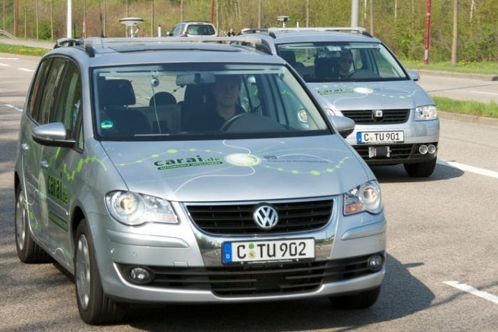
and integrity—Advanced Driver Assistance Systems (ADASs) Fig. 1. Typical urban scenario: Car-to-Car communication is used to dis-
like blind spot detectors or green driving assistants can be tribute raw GNSS measurements between vehicles. Furthermore, the stationary
realized and successfully deployed. During the last years, Road Side Unit (RSU) emits corrections to be used within the positioning
algorithm.
satellite-based positioning sensors like the Global Positioning
System (GPS) have emerged as standard solution for the
localization task. Low-cost single frequency GPS receivers are
nowadays integrated in almost any mid-range vehicle. While video cameras or lidar. For example, in [2] a vision-based
for most comfort applications (e.g. navigation systems) the algorithm for high-accurate vehicle localization with digital
typical performance of standalone Global Navigation Satellite maps is presented
System (GNSS) localization with app. 20 m is sufficient, good In this paper, the CoVeL system for lane-level vehicle
positioning quality cannot be assumed in general. For example, localization is presented. The CoVeL architecture is mainly
in dense urban areas where GPS signals may be blocked by build on GPS positioning and the emerging Car-to-Car (C2C)
buildings or vegetation, the localization accuracy may decrease communication protocol based on the 802.11p standard. The
dramatically. C2C communication is an important cornerstone of the In-
One possible solution to mitigate the weaknesses of telligent Car Initiative [3] of the European Commission and
standalone-GPS localization is the combination with other will be introduced widely by the year 2014. It will be shown,
independent sensor information. Especially, in the automotive that wireless communication in combination with standard
domain, additional sensor measurements from the in-vehicle inexpensive GPS receivers has a huge potential to improve the
ESP and ABS sensors (e.g. velocity and acceleration) are localization performance for vehicular applications up to lane-
available through the CAN bus. While the exclusively use level accuracy. Obviously, such an approach is favorable, as
of odometry observations to incrementally update the vehicle only standard sensors are used and no additional investments
position and pose is known as dead reckoning, the combination are necessary. In Fig. 1 a typical urban scenario is shown:
of GPS observations and odometry measurements represents CoVeL vehicles are communicating directly through C2C with
the GPS/INS integration [1]. Even though, the GPS/INS each other (orange arrows). Furthermore, a stationary Road
integration is useful to stabilize the positioning solution, it Side Unit (RSU) which acts as a gateway is installed at
cannot be used to further improve the absolute accuracy to an intersection. Through the C2C channel, corrections and
lane-level. Therefore, another approach is the introduction of raw GPS measurements are exchanged. With this information
land-mark-based positioning through additional sensors like available, each vehicle can refine its own position solution. The
Fig. 2. Schematic description of the CoVeL system for lane-level positioning. Sensor components are shown in green, while algorithms are indicated through
blue boxes. The Absolute positioning module generates an initial estimation of the vehicle position through a multi-sensor fusion of GPS measurements
and vehicular motion observations. Furthermore, wireless received corrections from EDAS are used to validate and enhance the GPS position. The Relative
positioning and the Group Map Matching are utilized to refine the absolute position to lane-level accuracy. The raw GNSS measurements—used for the
relative positioning—are received over a 802.11p C2C channel with a protocol extension.

focus of the paper is on the requirements of the communication                satellite. The satellite clock offset Dt can be taken from the
channel and the definition and implementation of the necessary                broadcasted ephemeris and is therefore assumed to known in
messages.                                                                     advance for each satellite, while the receiver clock offset dt
   The paper is structured as follows: In the next section the                remains unknown. Furthermore, the pseudorange is subject
fundamentals of GNSS positioning and its typical error sources                to a propagation delay caused by the ionosphere dion and
are introduced. Furthermore, the Car-to-Car communication                     troposphere dtrop . Since the satellite position derived from the
used in the CoVeL project is explained in detail. In section                  ephemeris may be inaccurate to a certain extent, the error term
three, the whole CoVeL system architecture is presented.                      deph is introduced. Other errors like measurement noise of the
Both, used sensors as well as algorithms are described briefly.               receiver or local phenomena like multipath are not covered
Section four is dedicated to the implementation of the required               by this model. If at least four pseudoranges are available
communication extension on top of the C2C stack and the                       the receiver position can be solved through a least-squares
message definitions. In section five first results are presented              algorithm or a Bayes filter implementation like the Kalman
and discussed. The paper concludes with a summary of the                      filter [5]. Unaccounted errors within the pseudoranges will
achieved results and gives an outlook of the next steps.                      normally lead to a bias in the final absolute position estimate.

                        II. F UNDAMENTALS                                     B. Vehicle-to-Vehicle Communication
   In this section the fundamentals of standalone GNSS lo-                       The wireless communication equipment used for this work
calization are described. The focus is mainly on identifying                  is based on the 802.11p standard. For sake of simplicity, this
the typical errors and how they can be mitigated. Moreover,                   can be seen as an adaptation of the well-known 802.11a stan-
the 802.11p standard which is used in the CoVeL project for                   dard used in home Wi-Fi networks for vehicular environments.
Car-to-Car communication is introduced.                                       The adaptation allows for flexible ad-hoc communication be-
                                                                              tween nodes. When a vehicle enters the communication range
A. GNSS Localization
                                                                              of another ITS station, they are instantaneous able to exchange
   Normally the determination of a GNSS position is based                     information without any further negotiation. Compared to the
on taking several raw GNSS measurements of one epoch                          variant used in the U.S., the 802.11p protocol in Europe
and processing them though a least-squares estimator. The                     operates at 5.8GHz and has 3 separate transmission channels
raw observations-often called pseudoranges-are time of flight                 available which should be used for different services. Typical
measurements between the receiver antenna and the visible                     ranges for communication reach up to 250 m, where the actual
satellites. As the position on earth is fully described by                    distance depends on environmental parameters like building
a three dimensional coordinate, at least three pseudoranges                   density and vegetation. For this reason, it is unlikely for
are needed for the localization solution in theory. Due to                    vehicles to have direct point-to-point connections with all
the unsynchronized receiver clock, a time bias between the                    other ITS stations in its vicinity. The hardware implemen-
satellites and the user receiver has to be considered too.                    tation used of the protocol was a small dedicated device of
Therefore, the unknown clock offset needs to be estimated                     NEC called Linkbird. Work is still ongoing in the European
through a fourth pseudorange observation. According to [4]                    Telecommunications Standards Institute (ETSI) to specify a
the pseudorange p can be modeled as:                                          network-layer protocol which can extend the communication
           p = r + c(dt − dT ) + dion + dtrop + deph ,                 (1)    range through geographical-based multi-hop routing. This so-
                                                                              called GeoNetworking protocol supports multiple approaches
In the given equation, c is the speed of light and r represents               to disseminate data. One of main approaches is geographical
the true geometric distance between the receiver and the                      broadcasting which allows broadcasting data to all nodes in
terrestrial counterpart named EDAS which can be received
over the internet. An analysis of the benefits when using
EGNOS/EDAS can be found in [6]. Within the CoVeL system,
a strategy to transmit EDAS data received at the stationary
Road Side Unit to the vehicles was developed.
B. Relative Positioning
The relative positioning component generates a relative
vector between a remote and the ego vehicle from a pair of si-
multaneous measured raw GNSS observations (pseudoranges).
The pseudoranges from the remote vehicle are received via the
C2C channel. For the relative vector determination, the correct
Fig. 3. Prototyping vehicles Carai1 & Carai2 used for the test drives.
synchronization of the measurements is important. Unhandled
time differences will lead to an bias within the difference
vector. A more detailed explanation of the relative positioning
a particular geographical location. This location can be either
algorithm implemented within the CoVeL system is given in
a circle, square or ellipse at a certain coordinate. Each ITS
[7].
station-even when not directly interested in the content- might
act as a repeater until the nodes in the destined location C. Group Map Matching
are reached. Another approach is topology broadcasting in
After the estimation of an initial vehicle position through
which data is broadcasted to all ITS station within a certain
the absolute positioning and the determination of the relative
number of hops. The Linkbird was prepared to run the latest
vectors to the remote vehicles, this information is passed to
implementation of Hitachi of the GeoNetworking protocol.
the Group Map Matching (GMM) component. The GMM im-
Safety related messages are typically sent over such a network-
plements a cooperative matching algorithm which—in contrast
layer. For these messages a reserved channel-called the control
to classical map matching—considers the position of the local
channel-is used to assure fast and reliable transmission. One
and remote vehicles at once. Through constrains introduced
typical representative of such a telegram is the Cooperative
by the lane-level digital map, this operation directly yields
Awareness Message (CAM) which is broadcasted by each
the present bias contained within the GPS position. Finally,
ITS station with a frequency of 1-10 Hz. This message con-
this bias is used to refine the initial absolute position to
tains in addition to position and kinetics information, also
the final position estimate which is then forwarded to the
breaking lights status for example. Most of these elementary
driver respectively application. In [8] a detailed description
messages are standardized in ETSI to ensure compatibility and
in combination with a simulation of the GMM algorithm is
interoperability between different vendors. As indicated in the
shown.
description above, these standards are very restrictive in only
transmitting small and generic messages. For this work, the D. Raw GNSS Data Definition
exchange of GNSS raw data was required. It was implemented
Each vehicle has a local GPS receiver installed which
on top of the GeoNetworking protocol as a vendor specific
delivers raw GNSS measurements. As the relative vectors are
extension and is described later in this paper.
generated from a pair of similar pseudoranges, each vehicle
III. C OV E L – S YSTEM -A RCHITECTURE needs to send out its own measurements through the C2C
In this section an overview of the CoVeL system architecture channel. The C2C standard—as currently defined by ETSI—
(see Fig. 2) is given. Each used sensor is introduced. Moreover, has not foreseen this type of data. Therefore, it was within the
the single algorithmic components and their relations are scope of the CoVeL project to define and implement such a
briefly explained. message, which was called GNSS raw data (GRM). In Table
I the information contained within a GRM message is shown.
A. GNSS Augmentation through EGNOS/EDAS
E. EDAS Data Transmission
As shown in section two, GNSS localization is subject
to different errors. One common source it the propagation In order to broadcast the EDAS data received at the station-
delay introduced by the ionosphere surrounding the earth. If ary RSU, a re-encoding and compression of these corrections
not handled properly, this delay directly leads to an bias in was necessary.
the positioning solution. As single frequency GPS receivers IV. E VALUATION M ETHODOLOGY
are not able to autonomously detect this delay, additional
information is needed. The European Commission operates A. Experimental Setup
an augmentation system called EGNOS which among others The previously described system was tested and evaluated
transmits the ionospheric path delay as a correction message. with two prototyping vehicles show in Fig. 3. These vehicles
In conjunction with EGNOS—which is emitted from geosta- are available at the University of Chemnitz and used as a
tionary satellites often not visible in urban areas—there is a research platform. A more detailed description is presentedTABLE I
C ONTENTS OF 802.11 P GNSS R AW M EASUREMENTS (GRM) M ESSAGE .
Parameter Description
Vehicle ID Unique id of sending vehicle. Chosen au-
tomatically by wireless stack.
GPS week & seconds GPS time when pseudoranges were mea-
sured.
Antenna Offset 3d-vector describing displacement of
GNSS antenna compared to vehicle coor-
dinate frame.
Number of measurements Indicates how many raw measurements
are contained in the current GRM mes-
sage.
GNSS raw data satellite n For each visible satellite this field con-
tains the measured pseudorange and the
corresponding SNR-ratio. This field will
be repeated n times.
Fig. 5. As the CoVeL system mainly aims to reach lane-level accuracy,
the positioning error was calculated for longitude and latitude (in respect of
Ublox-GPS EDAS vehicle heading) separately.
· Raw GPS data (4Hz) Reliable SBAS
· GPS Ephemeris corrections
· EGNOS (1Hz) Hence, only selected sequences which fulfill this require-
· Timing Information (1Hz) ment have been selected.
Positioning &
Communication PC Beside the comparison of the CoVeL algorithm, a GPS-only
and a GPS+EGNOS solution was calculated and evaluated
High accurate · Velocity (10Hz)
ground truth (20 Hz) · Yawrate (10Hz)
as well. To allow an assessment of the CoVeL positioning
performance for different ADAS applications, three common
Raw GPS data (1Hz)
In-Vehicle statistical error values are given:
Novatel SPAN 802.11p Kinematic 1) Circular error probability (CEP), which is defined as the
GPS+INS/RTK Linkbird Sensors radius of a circle which includes 50 % of the position
errors,
Fig. 4. Experimental system setup installed in each test vehicle for the
recording and evaluation of the GNSS raw data. 2) σ confidence interval, which means 65 % of the position
errors, and
3) 95 % confidence interval, which is used for safety-
in [9]. For the CoVeL evaluation, both vehicles contained a critical systems.
wireless C2C communication devices as well as low-cost GPS These values were measured for the average and the optimal
receivers which can deliver raw data. Fig. 4 shows a schematic geometrical constellation.
description of the experimental sensor setup installed in each
V. R ESULTS
vehicle.
A. Time Synchronization
B. Evaluation Criteria In Fig. 6 the influence of an uncompensated synchronization
error between the local GPS receiver and the remotely received
In order to evaluate the CoVeL positioning performance—
pseudoranges on the relative vector is shown. As the C2C
which aims to reach lane-level accuracy—different error mea-
channel introduces some non-deterministic delays, this needs
sures have been calculated. Therefore, the 2D positioning error
to be handled properly in the relative positioning component.
(horizontal error on road surface) between the CoVeL system
Clock errors of 250 ms already lead to an bias (purple line)
and the reference trajectory was investigated. Furthermore, this
of about 150 m, while the true (blue line) relative vector is
absolute 2D error was split into a lateral and longitudinal
about 15 m. A similar restriction applies to the right sub-figure.
component in respect of the vehicle coordinate frame (the
There, the influence of a small alternating delay is shown.
heading of the vehicle was taken from the ground truth
Again the purple line shows the estimated relative vector.
sensors) as shown in Fig. 5.
It should be noted, that the CoVeL system performance was B. V2V Communication Range
measured under two different assumptions: For this paper a test fleet of six vehicles was used to
• Average urban scenario: For this evaluation, the perfor- record real-world data for the evaluation. The vehicles were
mance was measured for the whole urban test drive. driving more or less organized on a predefined area within
• Optimal geometrical constellation: As explained in [10], the inner city ring of Chemnitz. In Fig. 7, the number of
the optimal (lane-level) performance of the CoVeL system communicating vehicles for a typical communication range
requires a good geometrical constellation of all vehicles. of 400m is shown. It has to be highlighted, that one of the sixFig. 6. Influence of time synchronization error to relative vector determination. The left sub-figure indicates that a time offset of 250 ms leads to a distance
error of 150 m in the relative vector. Small and variable time offsets (here 5 ms) lead to an unsteady difference vector as shown in the right sub-figure.
TABLE II TABLE III
L ATERAL P OSITIONING E RROR FOR D IFFERENT A LGORITHMS I MPACT ON C ONNECTED V2V N ODES TO P OSITIONING E RROR
Error Metric GPS EGNOS CoVeL (avg.) CoVeL (opt.) Number of Vehicles CEP 65 % 95 %
CEP 3.26 m 2.13 m 1.83 m 1.09 m 1 Vehicle 1.08 m 1.60 m 3.47 m
65 % 5.42 m 4.22 m 2.70 m 1.62 m 2 Vehicles 1.09 m 1.59 m 3.43 m
95 % 22.9 m 22.7 m 5.90 m 3.54 m 3 Vehicles 1.08 m 1.60 m 3.50 m
4 Vehicles 1.09 m 1.62 m 3.51 m
vehicles was excluded from the evaluation as its GPS receiver
is on suspicion to be broken. That is, the maximum number for the vehicles was present (see [8] for more details), only.
of vehicles available for communication is four. Here, the CoVeL system yields it’s best performance, as the
algorithm can fully benefit from the cooperative approach.
C. EGNOS Positioning Performance E. Influence of Connected Nodes
In this subsection the results focusing on EDAS/EGNOS Form the results of the simulative analysis in [8], an influ-
in comparison to GPS-only are presented. The Cumulative ence of the communicating V2X nodes to the positioning per-
Density Function (CDF) for the absolute positioning error in formance was assumed. As shown in Table III, this influence
Fig. 8 continuously illustrates how many percent of the posi- is not directly measureable from the results of this real world
tioning solutions are within a certain error bound. For the sake trail. The positioning error is more or less stable, no matter
of completeness, Table II shows the lateral component (with whether one or four vehicles were within the communication
respect of the vehicle coordinate frame) of the positioning range. It seems that the influence of the number of V2X nodes
error, only. It can be seen, that for average scenarios this value to the CoVeL algorithm is limited in this scenario. This can
is already quite reasonable (2.13 m for EGNOS). Nevertheless, be explained from the vehicle constellation within the urban
the EGNOS/EDAS-only solution is still not sufficient for lane- sequence. As the vehicles were driving not in an optimal
level accuracy. Additionally, it was shown, that for safety- constellation all the time (e.g. three vehicles behind each other
critical applications (95 %) EGNOS, as well as GPS, sufferers on the same lane will bring the same benefit like one vehicle,
from multipath phenomena which increase the error bound. the information is redundant), a larger number will generally
not improve positioning.
D. CoVeL Positioning Performance
In column four of Table II, the average results of the CoVeL VI. C ONCLUSION
positioning algorithm for the complete test drive in Chemnitz In this paper the concept for accurate lane-level posi-
are shown. For app. 50 % of the position fixes, the error is tioning of the CoVeL project was introduced. It has been
smaller than 1.83 m. It should be notate that the whole se- shown, how standard sensors—i.e. GPS receivers and C2C
quence does include sub-optimal geometrical constellations of communication units—available in modern vehicles can be
the CoVeL vehicles. Therefore, the full benefits of the CoVeL efficiently combined to improve the positioning accuracy. For
system cannot be expected. For the sake of clarity, column five this purpose, the definition and implementation for the GNSS
includes sequences were the theoretical optimal constellation raw data message was presented. The results proved that C2CFig. 7. Sequence from the urban validation campaign: The number of vehicles within a typical vehicle-to-vehicle communication range of 400m is shown.
Fig. 8. Cummulative Density Function (CDF) of GPS and EGNOS absolute positioning error. Compared to GPS-only, the EGNOS solution gives more
accurate results. Nevertheless, the lateral positioning error of 2.13 m is still not sufficient for the proposed lane-level approach.
communication in combination with GPS can successfully R EFERENCES
contribute to localization applications. It was highlighted, that [1] D. Bevly and C. Stewart, GNSS for Vehicle Control, ser. GNSS technol-
for safety applications, CoVeL detects and mitigates rough ogy and applications series. Artech House, 2010.
GPS outliers in urban scenarios and can therefore decrease [2] N. Mattern, R. Schubert, and G. Wanielik, “High-accurate vehicle
localization using digital maps and coherency images,” in Proceedings
the positioning error by 74 %. Furthermore, for good vehicle of the IEEE Intelligent Vehicles Symposium, 2010, pp. 462–469.
constellations the position error can even be lowered by 85 % [3] European Comission, “On the Intelligent Car Initiative ”Raising
compared to a standard GPS solution. Nevertheless, it was Awareness of ICT for Smarter, Safer and Cleaner Vehicles”,” 2006,
last checked: 15.12.2011. [Online]. Available: http://shortlink.org/
shown, that the positioning performance strongly depends IntelligenCars
on the vehicle constellation (i.e. number and geometrical [4] E. Kaplan and C. Hegarty, Understanding GPS: principles and applica-
arrangement of vehicles) and the road topology networks (e.g. tions. Artech House Publishers, 2006.
[5] B. Ristic, S. Arulampalam, and N. Gordon, Beyond the Kalman Filter
number of lanes and intersections). Moreover, the influence – Particle Filters for Tracking Applications. Artech House, 2004.
of time synchronization errors has been investigated. It turned [6] M. Obst, R. Schubert, and R. Streiter, “Benefit Analysis of EG-
out—that if not handled properly—to be critical, as it directly NOS/EDAS for Urban Road Transport Applications,” in Proceedings
of the 8th ITS European Congress, 2011.
introduces an error during the relative positioning. [7] M. Obst, E. Richter, and G. Wanielik, “Accurate Relative Localization
Future work should include a generic definition and de- for Land Vehicles with SBAS Corrected GPS / INS Integration and V2V
scription of a geometrical Dilution of Precision (DOP) metric Communication,” ION GNSS 2011 Proceedings, pp. 363–371, 2011.
[8] N. Mattern, M. Obst, R. Schubert, and G. Wanielik, “Simulative analysis
for cooperative systems (comparable to the HDOP value of of accuracy demands of co-operative localization in the covel project,”
GNSSs) which includes vehicle constellations and topology in Proceedings of the IEEE Intelligent Vehicles Symposium, 2011.
parameters. [9] R. Schubert, E. Richter, N. Mattern, P. Lindner, and G. Wanielik, Ad-
vanced microsystems for automotive applications 2010 : smart systems
for green cars and safe mobility. Springer, 2010, ch. A Concept Vehicle
ACKNOWLEDGMENT for Rapid Prototyping Of Advanced Driver Assistance Systems, pp. 211–
219.
This work was done as part of the CoVeL project which is [10] R. Schubert, N. Mattern, and M. Obst, “Cooperative Localization and
co-funded by the European Commission and carried out in the Map Matching for Urban Road Applications,” in 18th ITS World
context of the Seventh Framework Program. Congress, 2011.You can also read