A Controller for Autonomous Landing of AR.Drone
←
→
Page content transcription
If your browser does not render page correctly, please read the page content below
A Controller for Autonomous Landing of AR.Drone
                                       Roman Barták, Andrej Hraško, David Obdržálek
          Charles University in Prague, Faculty of Mathematics and Physics, Malostranské nám. 25, Praha, Czech Republic
                       E-mail: bartak@ktiml.mff.cuni.cz, andrej@hrasko.eu, david.obdrzalek@mff.cuni.cz

       Abstract: In recent years, many so called “robotic toys” appeared at the market. Though these devices are called toys
       and they are primarily intended for games, they provide a set of sensors and actuators that can be controlled from
       a computer. Hence these robotic devices may serve as non-expensive research tools, in particular for developing
       advanced software for controlling them. This paper describes a controller for landing of an AR.Drone, a quadricopter
       marketed by Parrot Inc. This controller is designed for fully autonomous landing to a given visual pattern and for
       hovering above the pattern. We will show how to collect input information for the controller and how to use it in
       a classical PID controller.
       Key Words: AR.Drone, Landing, PID Controller

                                                                   pictures from the drone camera, is transformed to distance
1    INTRODUCTION                                                  measures used as an input for a PID controller. We will
                                                                   also present an application developed to demonstrate the
Recent advancement of robotic research brought                     proposed approach.
non-expensive hardware with sophisticated sensors and              The paper is organized as follows. We will first describe
flexible motoric capabilities. Today robots are ready for          hardware of the AR.Drone platform and the ways it
performing advanced operations, but it seems that their            communicates with a computer connected via WiFi. After
major limitations lie in software. In our research, we are         that we will propose a method for measuring distance
using an AR.Drone – a quadricopter capable of flying in            between the drone and the landing point. The next section
any 3D direction (Figure 1). This drone has no                     will be devoted to the description of used PID controller.
manipulators; it is basically a flying robot with several          Presentation of the DroneLander – an application to
sensors including two cameras. Moreover, an AR.Drone               present the proposed techniques in practice – and a
has some basic stabilization mechanisms and it can be              summary of experimental results will conclude the paper.
controlled by setting pitch, roll, and yaw rather than
controlling the speed of its rotors. This makes it easier to       2     AR.DRONE PLATFORM
design software for AR.Drones as programmers can focus
                                                                   AR.Drone by Parrot Inc. [7] is a high-tech flying toy
on higher levels of control. Still the quadricopter is
performing in a real-life environment that is dynamic,             (Figure 1) that can be used for augmented-reality games.
continuous, partially observable, and stochastic [8]. So the       Technically, it is a quadricopter with sensors and a
                                                                   controller. As this device is very light (360-400 grams)
software must run in real time, the environment is not
                                                                   and therefore quite prone to wind disturbances, it is better
always as the agent perceives it, and finally, the things do
                                                                   suited for indoor environments. To a certain extent, it can
not always work as the agent intends.
                                                                   operate outdoors as well. Its main battery allows operation
                                                                   for about 13 minutes. For our work, we used the original
                                                                   AR.Drone, but there exists a newer version AR.Drone 2
                                                                   with better parameters. We describe here the selected
                                                                   parameters of the original AR.Drone as they influenced
                                                                   the decisions done.
                                                                   AR.Drone is controlled by a 32-bit 468 MHz ARM9 RISC
                                                                   processor with 128MB DDR-RAM running at 200MHz.
                                                                   This processing architecture controls the basic operations
                                                                   of the drone including stabilization. It is possible to install
                                                                   own programs there but due to a limited computing power
                                                                   we have decided to use an external computer.
                  Fig 1. AR.Drone by Parrot Inc.                   The core set of sensors consists of a 3-axis accelerometer,
                                                                   a 1-axis gyroscope, a 2-axis gyroscope, an ultrasound
In this paper we will describe a controller for autonomous         sensor (sonar), and a vertical downside camera. The 1-axis
landing of an AR.Drone. We will show how information               gyroscope measures yaw with the error 12° per minute
about the landing point, which is obtained by analyzing            during the flight or 4° per minute in the steady state. The
                                                                   2-axis gyroscope measures pitch and roll with the error
This work is supported by the Czech Science Foundation under the   0.2° per minute (see Figure 2 for the explanation of the
projects No. P103/10/1287 and P202/12/G061.                        yaw, roll, and pitch notions).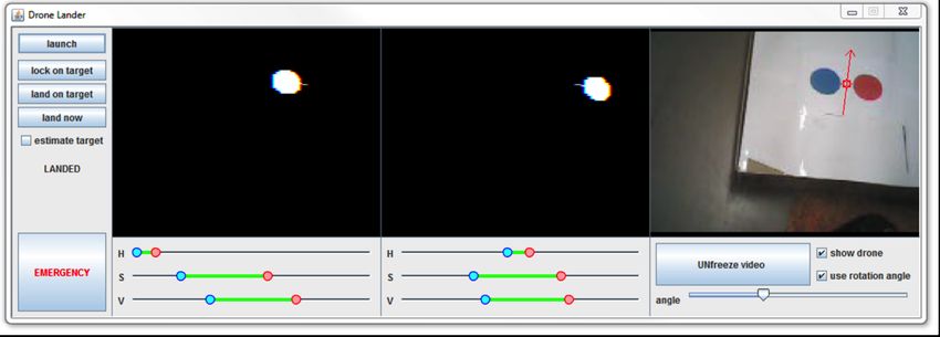
Pitch                                          visual sensors and they do not support horizontal
                                                              orientation, we decided for another approach. Our
                                                              motivation is exploiting an easy-to-made and customizable
                                                              landing pattern that makes target localization reliable.
                                                              For landing as well as for hovering above the landing
                                                              position we need to know where the landing point is
                                                              located. We use a specific landing graphical pattern
                                                              consisting of two colored discs. There are several reasons
                Roll                                          for choosing this pattern. First, it uniquely defines the
                                       Yaw
                                                              landing point – we use the point between the discs
                                                              (marked by a cross in Figure 3) – as well as the possible
                   Fig 2. Roll, yaw, and pitch.               orientation. Second, it is easy and robust to identify the
                                                              colored circles in the picture using the blob detection
The ultrasonic sensor measures the altitude of the drone in   algorithm [9] and some simple picture pre-processing
the range 20-600 cm. The CMOS vertical camera directs         techniques. We gave the technical details of this method
downward; it has a resolution 176 × 144 pixels                and its comparison with other methods in the paper [1].
corresponding to viewing angles 45° × 35° and provides a
video-stream with 60 frames per second. The system uses
this camera to estimate the speed of the drone via
measuring the optical flow. It is also used for calibration                                                    ×
of other sensors. There is a higher resolution horizontal
camera too, but we will not use it for landing.
The quadricopter can be controlled via WiFi from an           Fig 3. Landing pattern consisting of two colored discs (the cross
external device such as a computer. All the                   identifies the point that we use for landing).
communication is done using three UDP channels. A
Command channel allows sending commands to the drone.         Obviously, to detect the landing pattern we use the bottom
The device accepts the following commands with                camera of AR.Drone, which is the main source of
frequency 30Hz: takeoff, land, set limits (maximal            localization information for us. The picture processing
declination, speed, and altitude), calibrate sensors, swap    software OpenCV [6] is used to identify the landing point
cameras (see below), set rotation speeds of rotors, set       in the picture, but we still need to convert this information
pitch, roll, yaw, and vertical speed. A NavData channel       to metric information about the distance between the drone
provides information about the drone state again with         and the landing point. In this section we shall describe the
frequency 30Hz. The following information is provided:        method to measure that distance.
drone state (flying, steady, landing, takeoff, calibration,   Basically, we measure the distance using four attributes in
booting), sensor data (current pitch, roll, yaw, altitude,    the coordinate system: altitude (vertical distance in
battery level, and speed in all axes). Finally, a Stream      meters), front and side distances (horizontal distance in
channel provides visual information from the cameras.         meters), and rotation (Figure 4). The information about
Due to a limited bandwidth, only view from a single           altitude and rotation is given directly by the sensors; in
camera is available (or picture-in-picture).                  particular the ultrasound sensor provides altitude in meters
Although the AR.Drone has a native command to land, it        and the gyroscope provides yaw in degrees. It remains to
basically means go down without any control where to go.      compute the horizontal distances that are not directly
Therefore we decided to extend this functionality by          accessible from the sensors. This will be done by
defining a visual landing pattern and controlling the drone   analyzing the position of the landing point in the picture
to land exactly at a given location.                          captured by the bottom camera, using information about
                                                              altitude, and applying some trigonometry.
3    MEASURING DISTANCE TO THE GOAL
     POSITION                                                                               side
  view
     top
  view
         rotation

To control the drone we first need to know its exact
position with respect to the goal position. The difference                                                             side
  distance

between the current position and the goal position is then
fed to a controller that, briefly speaking, minimizes this
difference by controlling drone actions (see the next
                                                                                                                                                    front
  distance

                                                                        altitude


section). There exist many approaches for localizing
drones. Some of them are using external navigation or
specific sensors such as GPS; these are not appropriate for
our purposes as AR.Drone does not use such sensors and it
is mainly operating indoors. Others are based on purely
visual navigation for example using an H-shaped landing                  side
  distance

pattern [10] or a specific circular pattern [5]. These seem
more suitable for AR-Drone, but as they require better                            Fig 4. Relative position of drone and target.
Figure 5 shows the scheme of the situation that is used to
compute the horizontal distances. Drone camera is at point
D right above the point V; T is the target point; C1 and C2
are the edges of the area visible by the camera, and x is the
altitude measured by the ultrasound sensor. In practice we
use x to approximate the real altitude v as the angle α is
usually small and the ultrasound sensor has some small
error anyway. Note however, that the camera does not
provide the other measures directly; it gives a picture as
shown in Figure 5 (top left). Points T, S, C1, C2 are seen as
T’, S’, C’1, C’2 in the camera. We compute the real
distance in meters between T and V using the formula:
        dist(T,V) = v · tan(α+β).                                (1)
The ultrasound sonar gives altitude x (that approximates v)
in meters (with centimeter accuracy). Angle α is also
known from the sensors – it is either pitch for the                     Fig 5. A schematic drone position (a side view) and the view from
forward/backward distance or roll for the left/right                    the bottom camera (top left). Points T, S, C1, C2 are seen as T’, S’,
distance. Angle β is a relative angle between the actual                C’1 , C’2.
drone position and the target so it proportionally
corresponds to the distance between T’ and S’. We                      for rotation, and for altitude. The required value input for
measure this distance in pixels from the camera picture.               one PID controller is the target point x coordinate and the
This is not the real distance of points but the distance of            output is directly used for the low-level drone interface as
their projections in the camera picture. We already know               pitch and so on: the target point y coordinate is
the pixel distance between points C’1 and S’ (which is                 transformed by the respective controller to roll, the
defined by the camera resolution) and the angle γ (view                rotation to yaw and the altitude to vertical speed,
angle) from the camera properties (±72 pixels and ±17.5°               respectively. In the previous section, we described how to
for the longitudinal axis, ±88 pixels and ±22.5° for the               compute the errors for all these controllers. The
lateral axis). Hence can compute the angle β using the                 computation procedures behind all these controllers are
formula:                                                               identical; the only difference is in the setting of
                                                                       proportional, integral and derivative gain constants for the
  β = arctan(tan(γ/2) * pixel_dist(T’,S’) / pixel_dist(C’1,S’)). (2)
                                                                       four different controllers. Even these constants were tuned
For the forward/backward distance, the formula looks like:             experimentally; they result in the PID controllers having
  β = arctan(tan(17.5) * vert_pixel_dist(T’,S’) / 72).          (2a)   sufficient effect on the drone flight. Note also that we are
For the side distance, the formula looks like:                         not directly controlling the rotation speeds of propellers;
                                                                       instead, the controllers output required pitch, roll, yaw,
  β = arctan(tan(22.5) * horiz_pixel_dist(T’,S’) / 88).        (2b)    and the vertical speed according to the errors on their
Since we have computed the real relative position of the               respective inputs. These outputs are then fed to the drone
target (defined by a distances/angle in meters/degrees                 low-level control software described in Section 2, which
between target and drone for each axis) we can make the                results in the drone moving in the requested direction.
drone to approach the target using this information – to               As mentioned above, the minimal altitude recognized by
minimize the distances/angles (called errors) to a zero.               the ultrasonic sensor is about 25 cm. At this altitude the
                                                                       landing target is hardly visible by the bottom camera as the
4     DRONE CONTROLLER                                                 target pattern is too close to the camera. Also when light
During the landing procedure, we control the drone by                  drones are close to the surface, their own propellers cause
repeating the following steps:                                         a lot of turbulence and the drones become very hard to
 1. identifying the landing point in a video frame,                    control at low altitudes. Therefore we stop the landing
 2. finding the error – the real distance in meters                    procedure at the altitude of 30 cm where we switch off the
      between the current position and the target position,            motors. Hence this final stage of landing resembles a
                                                                       controlled fall. If one switches the drone motors at this low
 3. feeding the error to a controller,
                                                                       level, it does not usually impose any danger of breaking
 4. using the controller output to move the drone.
                                                                       the drone structure. That is because the drone does not fall
As the main control mechanism, the proportional–                       from high altitude and because the drone chassis is usually
integrative–derivative (PID) controllers are used. A PID               constructed shockproof enough to withstand exactly such
controller is a generic control loop feedback mechanism                kind of landing.
widely used in industrial control systems [4]. Its input is a
required value (attribute or property) of the controlled               4.1 Unexpected Events
object; during the operation, the PID controller measures              It may happen that the target is not identified in the current
this value and based on the difference between it and the              video frame. There can be several reasons for that situation
required value (the error) it changes the actuation.                   including a noise in the picture causing the blob detection
We use four PID controllers to control the drone, namely               algorithm to fail and unexpected movement of the drone
for forward/backward movement, for left/right movement,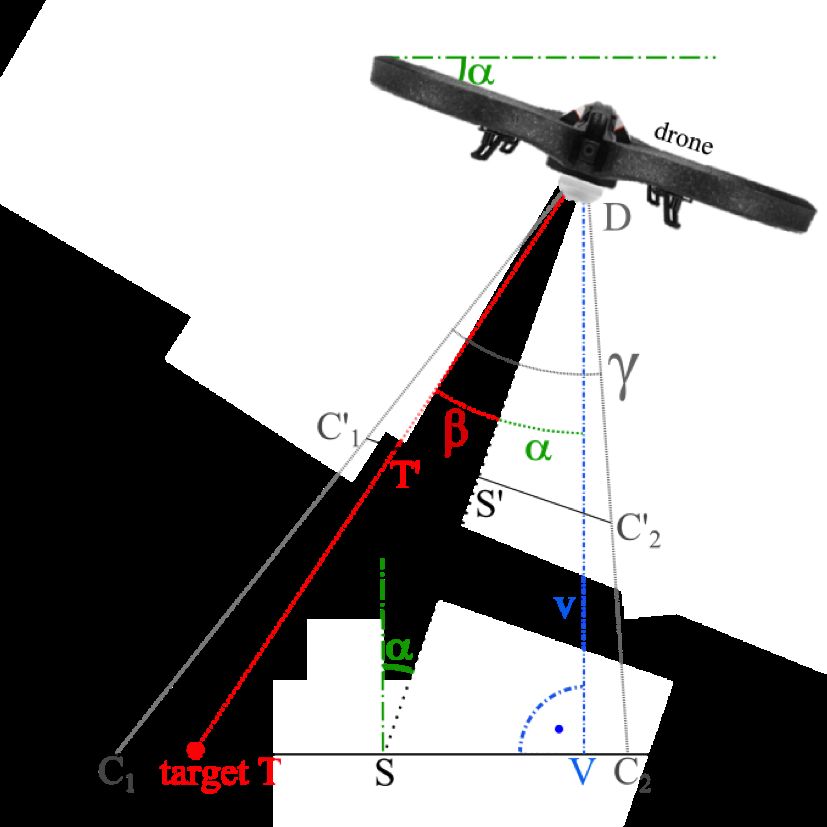
(user intervention, wind, turbulences etc.). In the default
mode, we simply assume that the target is still at the
original position (although temporarily invisible) and we
move the drone in the direction of the last time seen
position of the target. However, if the target is not
identified in ten consecutive video frames, we interrupt the
landing procedure and switch the drone to the hovering
mode to prevent unwanted movement. This approach                                      Fig 6. PID controller.
recovers easily from mistakes in the pattern recognition
procedure and ensures that the drone moves continuously.
                                                                  danger of reaching the setpoint but due to these inertia
For the second situation when the drone moves                     forces overshooting and departing it again, then stopping,
inappropriately to the intentions, we can optionally use a        returning and so on. That can lead in a long term to
more proactive approach. Based on data from the                   oscillation around the setpoint.
accelerometer, we can detect the drone movement
                                                                  The output of the integrative part is the sum of all errors
difference (measure passed distance by the accelerometer,
                                                                  since the start multiplied by the constant I (reset). We can
this is also called accelerometer based odometry). We can
                                                                  see that the magnitude of the output of this part grows over
compute the distance from the last known position of the
                                                                  time if the error is not zero. This is useful for example in
target by summing all the acceleration values for each axis
                                                                  situations when the system can’t reach the setpoint
since the target got lost and adding this summations to the
                                                                  because of external impact. When the error does not
appropriate last known target position abscissa. By this
                                                                  minimize over time, the power of the movement generated
information we have computed the estimated location of
                                                                  by this part increases and consecutively can rise high
the target even if this location is outside the visibility area
                                                                  enough to overcome the blocking forces.
of the bottom camera. If such situation happens, we move
the drone towards the expected location. However, if the          The output of the derivative part is the magnitude of the
target does not appear in the camera view according to the        error change (current cycle error value compared to the
estimated location where it should already be visible, we         previous cycle error value) multiplied by the constant D
interrupt this mode and switch the drone to the hovering          (rate). The power of this movement depends on the speed
mode to prevent unwanted moves like in the first case. The        of the system towards the setpoint (“velocity made good”)
accelerometer can be used to balance sudden changes of            and on the value of the constant D. Obviously using the
drone location, but due to its nature, it cannot provide          output value of this part we can determine that the system
accurate measurements for a long time and hence it is used        is approaching the setpoint too quickly. In such case, we
just as a short-term correction facility.                         can start to slow down, which may prevent the unwanted
                                                                  oscillation around the setpoint as mentioned above. For
4.2 PID controller                                                example when the drone is near the target, but it still has
                                                                  high velocity, the result of the proportional part will be
A PID controller (see Figure 6) is a control loop feedback
                                                                  near the zero, but the result of the derivative part will be a
mechanism with specifically defined transfer function – a
                                                                  higher value. The sum of these two values will be sent to
function that processes the input values to the output
                                                                  the drone and will cause the breaking movement.
values in every cycle of the loop while aiming for
minimizing the error. In our case the input is the computed       The outputs of the controllers are values saying how much
error (distance/angle in meters/degrees, see the Section 3)       percent of the maximum allowed tilt/vertical speed/angular
and the output is a control value for the drone low-level         speed the drone should execute. Simplified pseudo code of
controller. A point where the error of the system is              the PID algorithm is as follows:
minimal is called a setpoint and represents the target the        do forever:
                                                                      read(current_position);
controller wants to reach (and also the input value for the           current_error = setpoint – current_position;
controller). The transfer function is divided to three parts –        sum_error = sum_error + current_error;
the so called proportional, integrative and derivative parts.         output = P*current_error + I*sum_error +
Input of each part is the same as the input of the whole                       D*(current_error – last_error);
                                                                      last_error = current_error;
transfer function and the output of the transfer function is
the sum of outputs of the three individual parts. It should       When the constants P, I, and D are set correctly and
also be noted that the input and output values do not             therefore each part has appropriate impact to controller
necessarily have to have the same units; for example, in          output, the PID controller moves the drone towards the
our case the input is the error of the current control system     setpoint flawlessly and quickly without unnecessary
value but the output is the requested pitch, roll, yaw, and       movements and oscillations and stops and stays over it
vertical speed as explained earlier in this section.              even when the flying conditions are not perfect.
The output of the proportional part is directly dependent         In high abstraction we can imagine a use of the PID
on its input multiplied by the constant P (proportional           controller as an impact of a conjunction of three forces to
gain). We can see that this output value will always move         the drone – each with unique characteristic. The first force
the system in a direction towards the setpoint. The power         tends to move the drone always directly to the target, the
of this movement depends on the value of the error and on         second force helps to reach the target when the difference
the value of the constant P. When using this part on              between the position and the target is small and the third
systems which are affected by inertia forces, there is a          force slows down the drone as it approaches the target.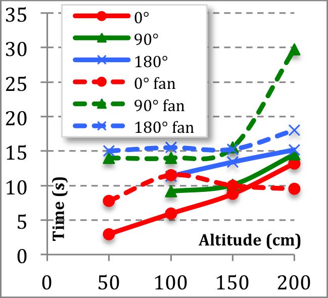
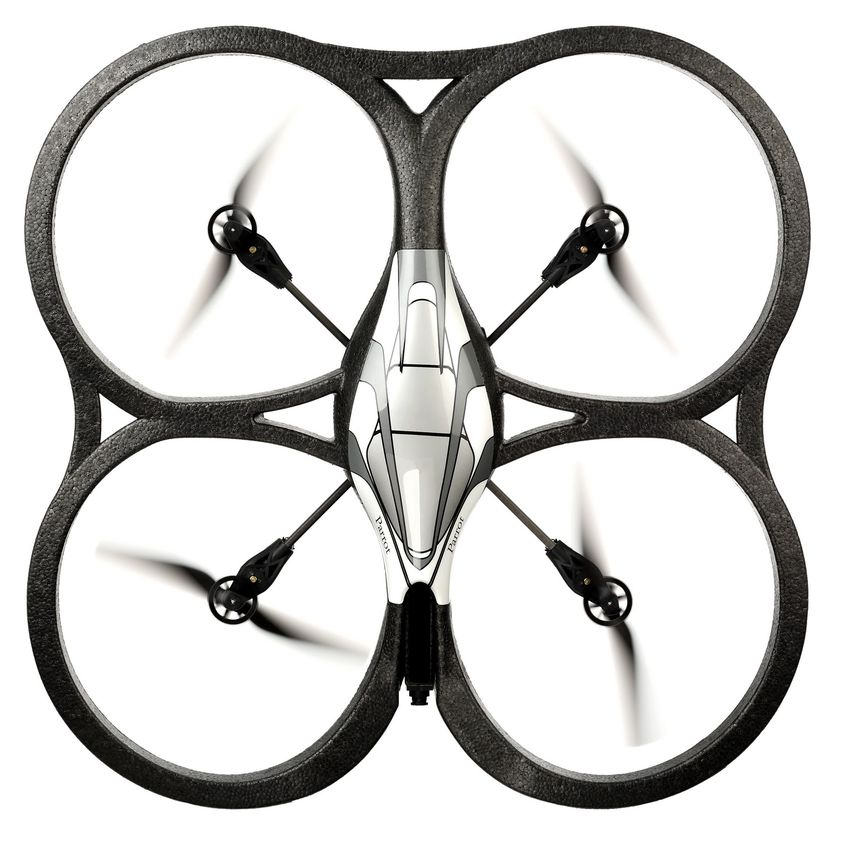
Fig 7. DroneLander user interface

4.3 Improving the controller                                       Secondly, the distance of the drone from the target is
                                                                   computed using data acquired from the sensors. Since the
The outputs from the PID controllers may be                        sensors are real-world sensors and not precise theoretical
post-processed before sending them to the drone. In our            model sensors, their output is noisy (and may be in
code, we have used for example the following                       principle noisy with different deviations in every
improvements which do not change the overall operation             measurement). These deviations may produce incorrect
but which fine-tune the flight:                                    error values used as inputs for the control loop, which may
    yaw_out = 10 * yaw / max(horiz_dist, 0.1);                     then result in dangerous jerky movements of the drone.
This makes the angular rotation speed dependent on the             This problem can be often eliminated by very simple
horizontal distance from the target. If the horizontal             filtering of the sensor data, for example by using floating
distance is higher than 0.1 meters, the angular rotation           average over a small number of consecutive measurements
speed is decreased proportionally. Using this modification         or using a Kalman filter if the characteristics of the
decreases the probability of losing the target while making        variance of a measured values are known.
risky moves such as rotation in situations when the target
is near the middle of camera view. Another refinement              5     USER INTERACTION
concerns the vertical (altitude) speed:                            For controlling the drone, we use the ControlTower
  alt_speed_out = 5 * alt_speed / max(angle, 5);                   application [3] that we extended by a new module named
This decreases the altitude speed when the difference from         DroneLander. This module is invoked from ControlTower
the angle we want to reach is bigger than 5 degrees. This          and provides its own user interface for defining the
formula leads to slowdown of the drone so that the drone           landing pattern and for basic control of the drone (buttons
has more time to rotate and reach the required angle.              on the very left of Figure 7).
These optimizations are used to enhance the stability and          DroneLander uses the bottom camera of AR.Drone as the
reliability of the landing procedure.                              major information source for landing. The user can freeze
When the target is not recognized successfully, several            a camera picture and set the HSV (hue, saturation, and
problems may arise. When a wrong place is recognized as            value/brightness) parameters to identify two color blobs in
a target or the target is not where it was supposed to be          the picture (left and center panels at Figure 7). Anytime
(e.g. while rediscovering the target after inaccurate              when the software recognizes these two blobs in the video
estimation), this target position change is fed to the             stream, it displays a red circle between them that marks
controller. Since this wrong position might be far away            the landing point (see the right most panel in Figure 7).
from the last recognized position, the target shift can be         The user can also optionally select the horizontal landing
interpreted by the controller as a jump. Even if this jump is      angle (yaw) of the drone marked by an arrow with respect
not real, output of the derivative part of the controller will     to these two blobs (if not activated then the drone simply
be high (because of the big change of the target position).        lands with any orientation).
Consecutively, the overall output of the controller would          The flight of a drone can be controlled manually through
be very high which would result in rapid move of the               the keyboard or a game controller via the ControlTower
drone. Such movements may be very dangerous for the                application. When the user (pilot) spots the landing pattern
system stability as such and transitively also for the chance      in the picture from the bottom camera, it is possible to start
of successful landing. This problem can be eliminated by           the landing process. We provide two options for using the
setting a threshold for the maximum target position change         landing pattern. Either the drone lands onto the pattern
speed (for example by limiting the maximum allowed                 (land on target) or the drone stays steadily directly above
value of the derivative part and/or by limiting the                the pattern at the current height and at the required angle
maximum allowed distance of two successive target                  (if activated) (lock on target). The unexpected drone
positions) and therefore restricting the impact of the             movements caused by external forces (wind, turbulence,
controller to the drone in such moments.                           user interaction etc.) are corrected by the landing software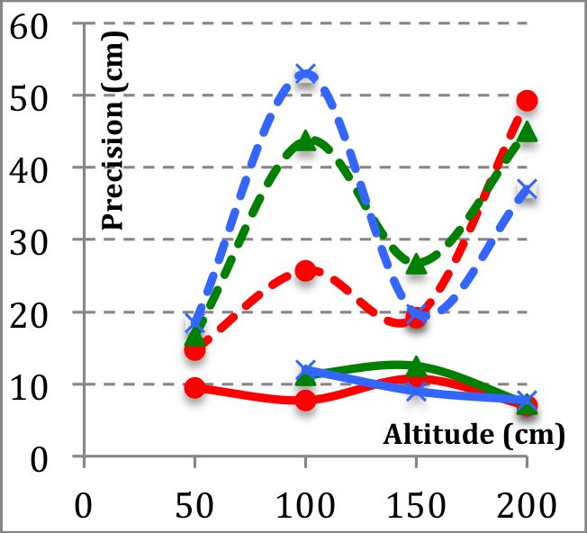
Fig 8. Dependence of landing time (left), precision (middle), and reliability (right) on the initial altitude (50, 100, 150, 200 cm) and orientation
                                                         relatively to the target (0°, 90°, 180°).

via the implemented controller. When the landing pattern                        conditions, that are however not expected indoors, the
disappears from the camera view, the system has a simple                        success of landing decreases significantly. Using heavier
function of trying to find the pattern by going in the                          drones would probably make it easier to resist wind.
direction where the pattern was lost (estimate target).
                                                                                7      CONCLUSIONS
6    EXPERIMENTAL RESULTS
                                                                                Autonomous landing is one of the key operations of
We evaluated the proposed autonomous landing software                           autonomous flying drones. It is especially important to use
experimentally by measuring reliability, precision, and                         a flexible approach that does not require expensive ground
speed of the landing process under different conditions. In                     equipment. In this paper we described a mechanism for
particular, we did two sets of experiments. In one set, there                   fully autonomous landing of AR.Drone that uses a simple
was no external disturbance of the landing process beyond                       and easy-to-made graphical pattern to identify the landing
the classical environmental conditions in the room. In the                      area. We use only the existing sensors in AR.Drone
second set, we added a fan at the altitude of 50 cm and                         including the bottom camera. The preliminary
directed it towards the landing area in the distance about                      experimental results showed that the landing procedure is
150 cm. The motivation was to see how the drone                                 reliable under normal conditions.
controller balances external interference with the landing
process. All experiments were done indoors; we placed the                       REFERENCES
drone right above the landing area at different altitudes                       [1] R. Barták, A. Hraško, D. Obdržálek, On Autonomous
(50-200 cm) and with different rotation with respect to the                          Landing of AR.Drone: Hands-on Experience. In
landing pattern (0°, 90°, 180°). For each combination of                             Proceedings of FLAIRS 2014, AAAI Press, 2014.
parameters, we repeated the landing process until we got                        [2] R. Brunelli, Template Matching Techniques in Computer
four successful landings. Then we measured the success                               Vision: Theory and Practice, Wiley, 2009.
rate as 4/#landings. For the successful landings we                             [3] ControlTower. Accessed March 10, 2014.
measured the time to land (in seconds) and the distance of                           https://code.google.com/p/javadrone/wiki/ControlTower.
the drone (its bottom camera) from the landing point (in                        [4] M. King. Process Control: A Practical Approach.
centimeters).                                                                        Chichester, UK: John Wiley & Sons Ltd., 2010.
Figure 8 shows the results as a function of the starting                        [5] S. Lange, N. Sünderhauf, P. Protzel, A Vision Based
                                                                                     Onboard Approach for Landing and Position Control of an
altitude. We differentiate between the initial orientations
                                                                                     Autonomous       Multirotor     UAV        in    GPS-Denied
and having the fan switched on and off. The results                                  Environments. International Conference on Advanced
confirm the expected behavior. Time to land increases                                Robotics, pp. 1-6, 2009.
with the increased altitude and with the increased initial                      [6] OpenCV. Accessed March 10, 2014.
rotation, as the drone needs to do more operations to land.                          http://opencv.org/.
When the fan is on (marked as fan in the figure), the                           [7] Parrot Inc., AR.Drone 2.0. Accessed March 10, 2014.
landing time is also longer, which is expected. Adding                               http://ardrone2.parrot.com/.
wind also decreases significantly the success rate and the                      [8] S. Russell and P. Norvig. Artificial Intelligence: A Modern
precision of landing, which is again an expected result.                             Approach. Third Edition. Prentice Hall, 2010.
The reson is that AR.Drone is very light and it is easy to                      [9] R. Szeliski. Computer Vision: Algorithms and Applications.
be blowed away. This is especially critical close to the                             Springer Verlag, 2010.
landing target as the drone may easily lose the target from                     [10] S. Yang, S.A. Scherer, A. Zell, An Onboard Monocular
the camera view.                                                                     Vision System for Autonomous Takeoff, Hovering and
                                                                                     Landing of a Micro Aerial Vehicle. Journal of Intelligent &
In summary, under the normal conditions, the drone is                                Robotic Systems, Volume 69, Issue 1-4, pp. 499-515, 2013.
landing reliably and with good precision. Under the windy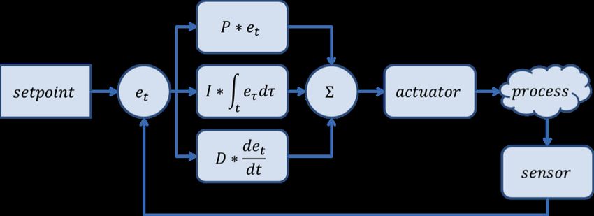
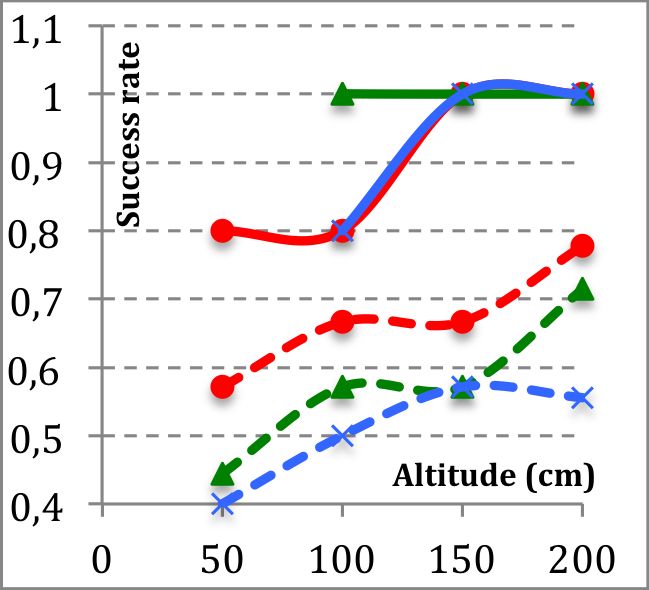
You can also read