The WHAT and WHY of - Toe Caster - Camber Kingpin Inclination - Thrust Angle Steering Angle - Wheel setback - Crypton Diagnostic Equipment
←
→
Page content transcription
If your browser does not render page correctly, please read the page content below
The
WHAT and WHY
     of

      Toe
      Caster - Camber
      Kingpin Inclination - Thrust Angle
      Steering Angle – Wheel setback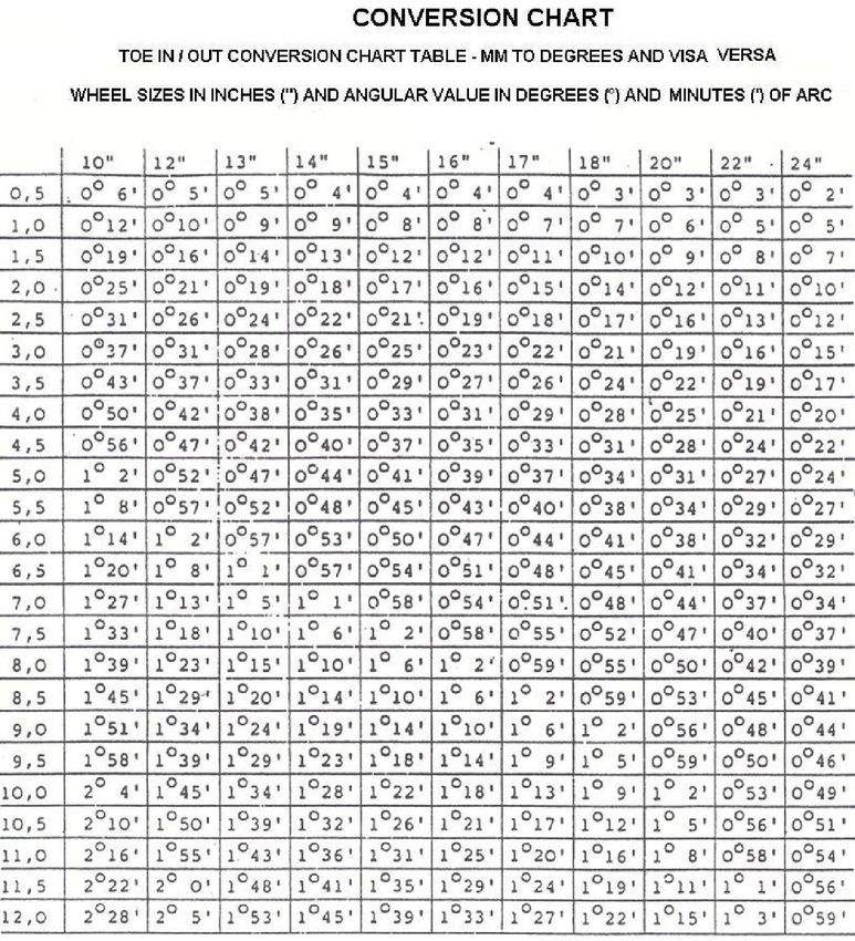
WHEEL ALIGNMENT SIMPLIFIED

Wheel alignment is often considered complicated and hard to understand

In the days of the rigid chassis construction with solid axles, when tyres were poor and road speeds were low, wheel
alignment was simply a matter of ensuring that the wheels rolled along the road in parallel paths. This was easily
accomplished by means of using a toe gauge or simple tape measure. The steering wheel could then also simply be
repositioned on the splines of the steering shaft. Camber and Caster was easily adjustable by means of shims.

Today wheel alignment is of course more sophisticated as there are several angles to consider when doing wheel
alignment on the modern vehicle with Independent suspension systems, good performing tyres and high road speeds.
Below are the most common angles and their terminology and for the correction of wheel alignment and the diagnoses
thereof, the understanding of the principals of these angles will become necessary.

Doing the actual corrections of wheel alignment is a fairly simple task and in many instances it is easily accomplished
by some mechanical adjustments.
However Wheel Alignment diagnosis is not so straightforward and one will need to understand the interaction between
the wheel alignment angles as well as the influence the various angles have on each other.
In addition there are also external factors one will need to consider.
Wheel Alignment Specifications are normally given in angular values
                                                  of degrees and minutes
                                                  A circle consists of 360 segments called DEGREES, symbolized by the
                                                  indicator °
                                                  Each DEGREE again has 60 segments called MINUTES symbolized by
                                                  the indicator ‘.
                                                  Therefore, for example a ½° (Degree) is also the same as 30’ (Minutes)
                                                  and ¼ ° (Degree) is the same as 15’ (Minutes)
                                                  Angular values are popular in that they are not reliant on wheel sizes
                                                  (rims), nevertheless in certain instances the values of TOE are given in
                                                  Millimetres. When this format is used then it is imperative that the wheel
                                                  sizes (rim) are known, simply for the fact that as one moves away from a
                                                  given point on the wheel (normally the centre) then the millimetre value
                                                  will increase the further one moves off the centre. If the wheel (rim) size
                                                  is used then the point of measurement becomes fixed.

Below is a conversion chart that clearly shows the change in values per wheel size (rim). For example a TOE value of
1mm on a wheel size of 10” = 10’ (minutes of angle) yet on a 15” wheel it represents 8’ (minutes of angle)

Vehicle manufacturers normally quote the
Wheel Alignment specifications as an “Actual
value with a plus or minus tolerance”. For
example TOE IN = Target data is +2mm +/-
1mm This means that the ideal setting is
+2mm, but a tolerance of 1mm is allowed to
the negative and 1mm to the positive, So the
Spread of TOE is from +1mm to +3mm on the
Positive side. Tyre wear should not be
excessive if the TOE is set between these two
extremes. However the ideal setting is at
+2mm. The only prerequisite is that both
wheels should be set at the same value.
How did we get to the extremes of +1mm to
+3mm? – Simple
+2mm taking away -1mm = +1mm (the one
extreme) and +2mm added to +1mm = +3mm
(the other extreme).
This rule also applies for degrees and minutes.
However one must be cautious in that when
doing the calculation one needs to bear in
mind that there are 60’ (minutes) to 1° (degree)
So let’s look at an example being CAMBER =
Target data is +30’ +/- 45’
The two extremes would be –15 (being +30’
taken away from - 45’) and +75’ (being +30’
added to +45’), however there are 60’ to 1° so
+75’ would be +1° 15’. Thus the two extremes
would be –15’ to +1°15’ So the spread of
CAMBER is from –15’ to +1°15’ and if kept in
this area it should not cause excessive tyre wear. However the ideal setting is at +30’
Wheel alignment can be termed “motion balance of the vehicle’s road wheels”
                                A vehicle’s wheels need to be aligned for two basic reasons.
                                a) To provide good road handling
                                b) and to ensure good even tyre wear
                                Good road handling means that the vehicle moves in a straight line without the continual
                                correction of the steering wheel. The vehicle must behave in a predictable manner when the
                                brakes are applied, or a corner is taken.
                                Good even tyre wear means all four tyres will last as long as possible
This can be achieved through “motion balance” which occurs when the wheels roll without scuffing, dragging or slipping
under all road operating conditions. This gives greater safety in driving, easier steering, longer tyre life and less wear on
the parts that make up the front and rear suspension of the vehicle. The ideal is for all tyres to always be in contact with
the road, always rolling, never skidding forward or sideways. Modern suspensions, properly aligned, can come remarkably
close in achieving this.
Motion balance is therefore the delicate balance of many different factors such as tyre type, tyre sizes, tread design, tyre
inflation, weight distribution suspension condition

This in simplicity means that the road wheels are so aligned that once the “laden” vehicle is in motion (with all of the
steering and suspension component play eliminated) all road wheels should be parallel to the vehicle centre line,
coinciding with the direction of travel,
Ideally the tyre tread area will meet with the road surface at 90° and be parallel with the direction of travel allowing for
even tyre wear

In practice, compliance is virtually impossible, due to the variances in the road surface as well at the continuos changing
position of the vehicle in motion.
However by adhering to the manufacturer’s wheel alignment specifications and setting the angles within the stated
tolerances should allow for a situation to be maintained resulting in EVEN tyre wear of the road wheels.

The True test of correct wheel alignment
adjustments is thus the resultant condition of
the tyres after several thousand kilometers
have been done. If no uneven tyre wear is
evident and the vehicle has shown stability
on the road then the diagnosis and correction
of the wheel alignment angles have been
correctly done.

Ready for Alignment?
Not yet!

Even by having an understanding of the various wheel alignment angles, we may not yet be ready to perform the tasks
related to wheel alignment as we will firstly need to understand the importance of the various articles of equipment that is
associated with wheel alignment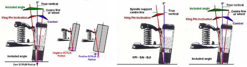
First and foremost we have the wheel alignment unit, which in most instances today will be an
                      expensive Computerised unit. Most of the computing functions and mathematical and trigonometry
                      calculations will be done for the operator, resultant in the display of actual values in relation to
                      Vehicle Manufacturers specifications, for the interpretation of diagnosis.
                      As many of these units are “Electronically calibrated”, and having no mechanical moving parts,
                      they should retain the calibration values and ensure “peace of mind” in the resultant wheel
                      alignment adjustments.
However there are other factors of critical significance that will most certainly have an effect on the performance of the
wheel alignment unit.
                                                            Items such as the condition of the “measurement bay” levels be it
                                                            a 4 Post vehicle Lift or Pit Rack.
                                                            If such a unit is out of level by as little a 5 mm across the front
                                                            turntables or rear slip plates then in all probability the Camber of
                                                            the vehicle readings will be out by as much as 18’ of angle. If this
                                                            is the case then the 18’ minutes of angle is an “initial fault amount
                                                            “that will be included in the values as displayed by the wheel
                                                            alignment unit. A fault that is not indicative of the vehicle, neither
                                                    of the wheel alignment unit, but rather that of the measurement bay.
                                                    Just imagine the tyre wear if the Camber of the vehicle is changed by 18’
                                                    (either to the plus or minus side) and the confusion emanating therefrom,
                                                    as you have only set the vehicle into actual specification as required. –
You did not know that there exist an 18’ “out of level” fault in your “measurement bay” – this however
has now been included in the wheel alignment results

Equally if there is excessive play in the locating attachment point between the “measuring component”
and the wheel clamp. When tightening the “wing nut” the measuring head could move in the vertical or
horizontal plane, again creating “faults” in both the Camber and Toe values.

Turntable for the front wheels and slip plates for the rear wheels could cause a faulty
reading if they should “stick” or be reluctant to move freely as the wheels are turned
or when Wheel Alignment adjustments are made.

It should also be of importance to note the various requirements from the vehicle manufacturers. Whether the vehicle
                                should be in the laden or un-laden position, and what the relevant “riding heights” are.
                                Checking the relevant Riding Heights is not only important as a vehicle manufacturer
                                requirement but can also be used in the diagnosis of Wheel Alignment problems caused by
                                other external factors such as Suspension components etc.
                                Many people believe that solid rear axles, because they cannot be adjusted are therefore not
                                of relevance. This is only partially correct for a variance in riding height between the left hand
and right hand side of the vehicle can have an influence of the “Thrust” of the
rear axle, especially if the “LOAD” is placed on one side. Equally there is the
same effect if one of the springs has sagged. What happens is that the
perpendicular distance cb (unladen wheel) changes in length to the
perpendicular distance ca (laden wheel). This is because the movement
between points a & b describe an arc around point c. With the perpendicular
distance ca being longer than the perpendicular distance cb the axle is
moved further back on the loaded wheel thus causing a “thrust angle”. This
“thrust angle” needs to be attended to before attempting to correct the front
TOE and or other wheel alignment angles.

Another area is the age of the vehicle in “kilometers” in that as the front wheels
are linked to each other via the steering components there exist a certain amount of play in these linkages. When the
vehicle speeds up, the rotational centrifugal forces tend to force the wheels to comply with the direction of travel. In this
movement all the “play of the components” are taken up and the steering linkages then become a single “rigid” unit. In
other words when the road wheels are set to a “Toe in” position the wheels will tend to veer outwards and will continue to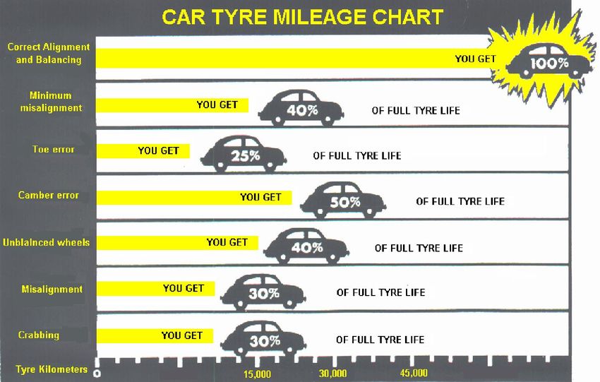
do so until all the steering components linkage play has been taken up. At this point the road wheels should be parallel to
the direction of travel.

                                             However, over a length of time with more and more kilometer’s being done,
                                             the play in the ball joints tends to become more evident and a TOE IN setting
                                             could become a TOE OUT setting. Some manufacturers promote the use of a
                                             “Compression Rod” that is to be inserted between the front wheels when
                                             doing TOE adjustments. The “Force” exerted, by this rod tends to take up the
                                             play in the ball joints.
                                             The TOE thus set is consistent to the manufacturer’s requirement at all vehicle
                                             speeds.

It is of equal importance that all the other angles remain in “balance” to each other, within the required Motor
Manufacturers Specifications, when the vehicle is in motion

This statement is of great importance in wheel alignment diagnosis in that all the wheel alignment angles of a vehicle
interact with each other. Commonly it can be deemed that they are inter-linked and the actions of one angle have an
influence on another.
Take the front axle of a vehicle and it will be noted that CAMBER, CASTER, KPI and TOE are
Three dimensionally linked to each other via the steering and suspension components.

                                      Press down on the bodywork and it will be noted that not one angle but all angles
                                      change in values. So the Importance of vehicle “LOAD” and “Riding heights” are
                                      also important.

                                      In all these factors there is one commonality and that is the Vehicle Manufacturers
                                      Specifications.

                                       Which in all circumstances must be complied with. Especially relating to the desired
                                      format used of “Actual Value and a plus and minus tolerance”

E.g. TOE IN = +5mm +/- 1mm
This means that +5mm is the “ideal setting”. The tolerance bandwidth of 1mm either way allows for the acceptable
movement of the suspension and steering components.
So the allowable range of acceptable TOE IN change is from +4mm (Ideal setting of +5mm taking away -1mm)
to +6mm (Ideal setting of +5mm added to +1mm).
This method allows for a TOE change of 1mm either way from the ideal setting of +5mm, and as such should cause no
tyre wear if maintained in these parameters. It does not however mean that if the TOE is set at +4mm or +6mm it is
correct. If it is set at the lower +4mm and the upper at +6mm any movement of TOE below +4mm and above +6mm will
then be out of spec and may lead to TOE IN or TOE OUT tyre wear.
This equally applies to CAMBER and CASTER settings (as well as all the other angles)
To endorse this the Vehicle Manufacturers are now supplying specifications with indications of Maximum Allowable
Differences (e.g. Cross TOE, Cross CAMBER etc)

                       Road Crown
                       A crowned road means that the outside of the lane is lower than the inside of the lane. This
                       improves the drainage of the road but adversely affects vehicle handling. Road crown must be
                       compensated for in alignment settings because a vehicle driving on a crowned road leans to the
                       lower side of the lane, being the outside of the lane causing some weight transfer to this side, and
                       the camber changes slightly more positive. This combination creates a pull or drift of the vehicle
                       towards the outside of the lane.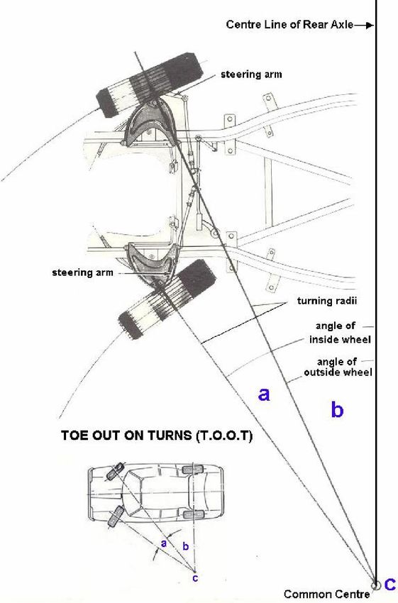
Wheel alignment is always started from the REAR AXLE working through to the FRONT AXLE,
even when work is only required to be performed on the FRONT AXLE

CHAPTER 1: Axis of Symmetry - Geometric centerline
The Geometric centerline of the vehicle is established by connecting a line between the
theoretical midpoint of the front spindles and the theoretical midpoint of the rear axle.

---------------------------------------------------------------------------------------------------------------------------------------------------------------
CHAPTER 2: THRUST ANGLE (THRUST LINE)

THRUST LINE is determined by bisecting the rear total toe. To bisect the rear total toe, lines that
are parallel to the tyre/wheel assembly are drawn until they intersect. Another line that starts
where the geometric centerline and rear axle intersect is drawn to the intersection of the
tyre/wheel lines. This line is the Thrust Line. When you have a thrust line to the left it is
considered Negative and when it is to the right it is considered Positive.

THRUST ANGLE is the direction the rear wheels are positioned in relation to the vehicle
centre line. It is caused by the misalignment of the rear axle and wheels

A NEGATIVE Thrust Angle (a1) will force the rear of the vehicle to move out to the LEFT side (a2)
causing the front wheels to turn to the LEFT as they align themselves for the straight-ahead
position. This action will in turn cause the steering wheel spoke to be offset to the LEFT once the
vehicle is in forward motion

Likewise a POSITIVE Thrust Angle (b1) will force the rear of the vehicle to move out to the RIGHT side (b2) causing the
front wheels to turn to the RIGHT as they align themselves for the straight-ahead position. This action will in turn cause
the steering wheel spoke to be offset to the RIGHT once the vehicle is in forward motion

HARMFUL EFFECTS OF INCORRECT THRUST ANGLE
Ø Excessive uneven tyre wear
Ø Vehicle pulls to one side
Ø Crooked, skew, offset steering
  wheel spoke
Ø Steering wheel misalignment
Ø “Crabbing “ of vehicle
Ø Front and Rear Wheel misalignment

Thus the importance of the correction of the “Thrust angle”
cannot be neglected in the correction of the vehicle Wheel
Alignment. This angle needs to be checked and corrected
before any other wheel alignment angles are checked or
corrected.

Many of the modern vehicles do not allow for the
mechanical repositioning of the steering spoke to a
centralized position (Common practice in the past was to
remove the steering wheel from the steering shaft and
reposition on the splines). Many of the modern Steering
wheels are fitted with “air bags” and the steering wheel is commonly located on the steering shaft by means of a “key way”
---------------------------------------------------------------------------------------------------------------------------------------------------------------
CHAPTER 3: REAR CAMBER
Rear Camber is the inward or outward tilt of the top of the tyre/wheel assembly from true vertical. If the top of the
                       tyre/wheel assembly is Tilted Inward, it has a Negative Camber.
                       If the top of the tyre/wheel assembly is Tilted Outward, it has a Positive Camber.

                                Rear camber is not adjustable on most rear wheel drive vehicles.

                                These vehicles are built with zero camber setting and are strong enough not to flex or bend under
                                normal load. Most front wheel drive vehicles have a manufacturer’s specification calling for a
                                slight amount of rear camber, usually a small amount of negative camber for cornering stability.
                                 See Chapter 7 or more information on CAMBER

---------------------------------------------------------------------------------------------------------------------------------------------------------------
CHAPTER 4: REAR TOE
 Measuring Individual rear toe using Geometric Centerline
                                         Toe-In (Positive Toe) is when the front of the rear wheel is closer to the geometric
                                         centerline than the rear of the same rear wheel. (The distance a1 is shorter than a3 &
                                         Distance a2 is shorter than a4)

                                        Toe-Out (Negative Toe) is when the front of the rear wheel is farther from the geometric
                                        centerline than the rear of the same rear wheel. (The distance a1 is longer than a3 &
                                        Distance a2 is shorter than a4)

                                         Measuring rear toe using Total Toe
                                        Toe-In (Positive Toe) exists where the distance of the front of both rear wheels on the
                                        common rear axle is closer together than the rear of the same rear wheels. (The Total
                                        combined distances of a1 and a2 is shorter than the total combined distance of a3 & a4)

                                        Toe-Out (Negative Toe) exists when the distance between the front of both rear wheels on
                                        the common rear axle is farther apart than the rear of the same rear wheels. . (The Total
                                        combined distances of a1 and a2 is longer than the total combined distance of a3 & a4)

REAR TOE adjustment is the most critical factor as it has s decisive influence on all other angles regarding tyre wear,
mileage, and handling. Rear TOE corrections should first be done before any attempt is made to correct the FRONT TOE
See Chapter 9 for more information on TOE

----------------------------------------------------------------------------------------------------------------------------------------------------------------

CHAPTER 5: REAR SETBACK

Rear setback is a measurement in reference to the rear wheels by an imaginary line drawn
perpendicular to the geometric centerline of the vehicle, and is measured as an angle. If a vehicle has
rear setback, one rear tyre/wheel assembly is further back from this imaginary line than the other.
Some causes of rear setback may be from frame, chassis, and rear cradle misalignment due to
collision.
 If the vehicle has a Rear setback condition, the vehicle may pull to the opposite side of the setback.

---------------------------------------------------------------------------------------------------------------------------------------------------------------
CHAPTER 6: CASTER
CASTER is a non tyre wearing angle and in some cases is non adjustable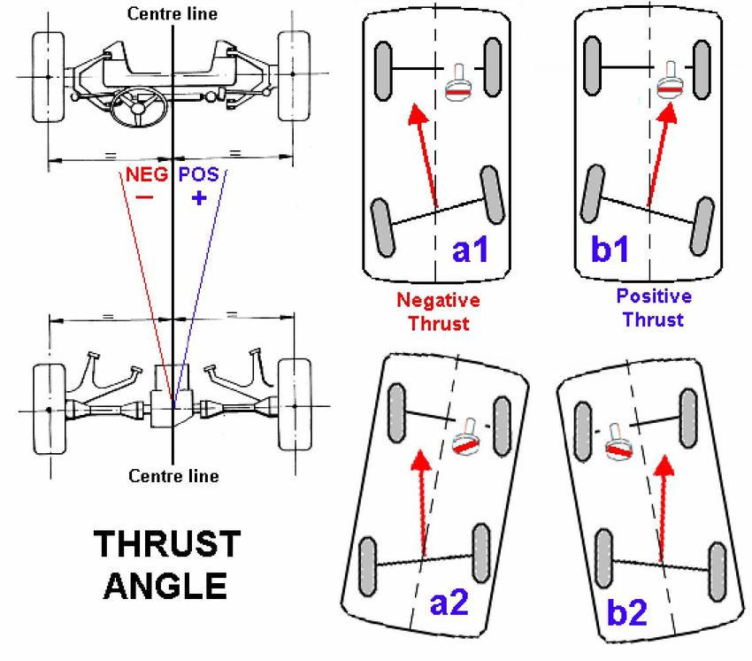
CASTER is the FORWARD or BACKWARD tilt of the steering axis, in relation to the true vertical, when viewed
from the side of the vehicle. (The steering axis is the imaginary line drawn through both ball joints and lower control
arms or through the lower ball joint and the upper pivot point of a McPherson strut)
Simply put it is the forward or backward tilt of the upper ball joint (or top of strut) relative to the position of the lower ball
joint.

If this line intersects the road ahead of the point of tyre contact the CASTER is said to be Positive (+)
If this line intersects the road behind the point of tyre contact the CASTER is said to be Negative (-)

The effect of Positive CASTER on the front wheel of a bicycle allows for the bicycle to continue in a straight-ahead
position even when your hands are taken off the handlebars.
Positive CASTER contributes to the tendency of the vehicle to move in a straight-ahead position and for the front wheels,
with minimum amount of resistance to return to the straight-ahead position, after turning.

Excessive Positive (+) CASTER makes the steering effort harder, increases road shocks and
enhances wheel shimmering.
Excessive Negative (-) CASTER makes the steering effort lighter but may cause the vehicle to
wander and even uncontrollable in cross winds.

A vehicle will have the tendency to move (pull) in the direction with the most Negative (-) CASTER
or with the least Positive (+) CASTER.
Rolling resistance tends to pull the point of road contact back. So a ZERO setting in CASTER may
actually become Negative (-) once the vehicle starts to move forward.

THE PURPOSE OF CASTER

Ø To gain directional control of the vehicle by causing the front wheels to maintain straight ahead position of return to straight
  ahead position out of a turn
Ø To offset road crown.

HARMFUL EFFECTS OF INCORRECT CASTER
Ø Unequal Caster causes the vehicle to pull toward the side of least Caster
Ø Too little Caster causes wander and weave, Steering control is touchy and sensitive
Ø Too little Caster caused instability at high speeds
Ø Too much Caster causes hard steering
Ø Too much Caster causes excessive road shock and shimmy.

Caster adjustment Methods
1) Shims 2) Strut rod 3) Cradle movement 4) Cams 5) Strut rotation 6)
Slotted frame 7) Offset ball joints

When doing CASTER adjustments using shims then
a) To move the wheel NEGATIVE (Rearward) ADD a shim to the Front or
   REMOVE a shim at the rear.
b) To move the wheel POSITIVE (Forward) REMOVE a shim at the Front or
   ADD a shim to the rear

When doing CASTER by adjusting the length of the Strut Rod
a) To move the wheel NEGATIVE (Rearward) ADD a shim or lengthen the
   Strut Rod by Nut adjustment
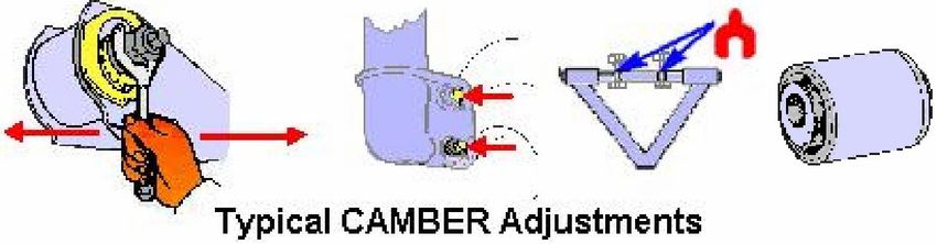
b) To move the wheel POSITIVE (Forward) REMOVE a shim or shorten the Strut Rod by Nut adjustment
The spread of CASTER settings must stay within the Vehicle Manufacturers specification and tolerance parameters

Special attention must be given to the requirement of the values specified by the vehicle manufacturer with regards to the
maximum allowable differences between the Left and Right hand wheel
---------------------------------------------------------------------------------------------------------------------------------------------------------------

CHAPTER 7: CAMBER

Camber is a tyre-wearing angle and in some cases is non-adjustable

CAMBER is the “Inward or outward” tilt of the wheels when viewed from the Front of the vehicle in relation to the
true vertical
When the top of the wheel leans outwards of the vehicle then the CAMBER is Positive (+). If the wheel leans inwards of
the vehicle the CAMBER is said to be Negative (-)

Zero (0°) CAMBER, where the wheel is exactly perpendicular to the road service and meets with the road at 90° is the
ideal setting for the longest tyre life. However due to the crown of the roads (sloping to the left or right) Positive (+) or
Negative (-) CAMBER settings is applied to obtain the desired results in tyre life and vehicle stability.
A small amount of “extra” CAMBER, for instance, helps compensate for future sagging of the suspension, while in racing
cars a Negative (-) CAMBER adjustment is often used to produce better tyre grip in cornering.

All things being equal, a vehicle will tend to pull towards the side of the vehicle with the most Positive (+) CAMBER. This is
because a tilted tyre acts like a section of a cone and a cone when rolled will always roll in a circle.

Where CAMBER conforms within the range of Vehicle Manufacturers specifications, the load weight is evenly distributed
on the spindle (stub axle) and bearings
CAMBER will change under weight (passenger and load) to varying degrees and certain Vehicle manufacturers give
different angles of CAMBER for different riding heights. These must be complied with. When preferred specifications be
given, CAMBER should be adjusted to the preferred settings.

Tyre wear from incorrect CAMBER
By rubbing the palm of your hand across the tread area of the tyre no “feathering” should be felt.
If the tyre wears on the inside section of the tread width the CAMBER was too excessive on the Negative (-) side
If the tyre wears on the outside section of the tread width the CAMBER was too excessive on the Positive (+) side
THE PURPOSE OF CAMBER
Ø To bring the road contact of the tyre more nearly under the point of load.
Ø To provide easy steering by having the weight of the vehicle borne on the inner wheel bearing and spindle
Ø To prevent uneven tyre wear

HARMFUL EFFECTS OF INCORRECT CAMBER
Ø Excessive wear to ball joints & suspension parts
Ø Excessive wear to wheel bearings.
Ø Excessive wear to one side of tyre tread (Negative Camber – inside wear * Positive Camber – outside wear)
Ø Excessive unequal Camber will cause vehicle pull to the side that has the most positive Camber

Camber adjustment Methods
1) Shims 2) Ball Joint rotation 3) Offset bearing plate 4) Cams 5) Strut rotation 6) Cam bolts 7) Offset ball joints 8)
Slotted frame 9) Wedges 10) Offset bushes 11) Eccentrics

When doing CAMBER adjustments using shims then
a) To move the wheel NEGATIVE (Inward at the top) REMOVE an equal amount of shim from the Front and Rear.
   Removing shims will allow the wheel to move inwards at the top and away from the True vertical. The more shims that
   are removed the more NEGATIVE the CAMBER will become
b) To move the wheel POSITIVE (Outward at the top) ADD an equal amount of shim to the Front and the Rear .Adding
   shims will allow the wheel to move outwards at the top and away from the True vertical .The more shims that are
   added the more POSITIVE the CAMBER will become

The spread of CAMBER settings must stay within the Vehicle Manufacturers specification and tolerance parameters.
Special attention must be given to the requirement of the values specified by the vehicle manufacturer with regards to the
maximum allowable differences between the Left and Right hand wheel
---------------------------------------------------------------------------------------------------------------------------------------------------------------

CHAPTER 8: Kingpin Inclination (KPI) – Steering Axis Inclination (SAI) - Ball Joint Inclination (BJI)

KPI, SAI, BJI is a non tyre wearing angle and is non adjustable

It is the angle between the steering axis and the vertical, when viewed from the front
This is so designed into the suspension geometry to cause the spindle to describe an arc when the wheels are turned.
The high point of the arc is the straight-ahead position and as such, when you steer to either side, you are actually slightly
lifting the vehicle. Gravity helps to return the wheels to a straight-ahead position.
Kingpin (SAI) Inclination is a directional control angle and is measured in Degrees and Minutes.
It is the amount the spindle support centre line is tilted from a pure vertical.

Kingpin (SAI) Inclination combined with CAMBER becomes the included angle and the relationship between these two
angles does not change except when the spindle or spindle support arm (ball joint) becomes bent.
The KPI (SAI) must be equal (within +/-30’) on both sides of the car, irrespective of the camber angle. If it is not equal the
scrub radii will not be equal and strange handling will result.

What is scrub radius?
When compared at ground level, the distance between the KPI / SAI line and the vertical centerline of the tyre tread is
called the scrub radius. If this line intersects at the road surface, a zero scrub radius exists. When the intersection is below
the surface of the road, the scrub radius is Positive. Conversely, when the lines intersect above the road, the scrub radius
is said to be Negative.
Squirm occurs when the scrub radius is at zero. This occurs when the point intersects at exactly on the centre of the tyre
footprint, this causes scrubbing action in opposite directions when the wheels are turned. Tyre wear and some instability
in corners is the result.
Vehicles with Mac Pherson strut suspensions normally have a negative scrub radius. Even though scrub radius in itself is
not directly adjustable, it will be changed if the upper steering axis point or spindle angle is changed when adjusting
Camber. This is the case on a Mac Pherson strut suspension with the Camber adjustment at the steering knuckle.
Because Camber is usually kept within 15’ side to side, the resulting scrub radius difference is negligible.
Negative scrub radius decreases torque steer and improves stability in the event of brake failure. Short & Long Arm (SLA)
suspensions usually have a positive scrub radius. With this suspension, the scrub radius is not adjustable.
The greater the scrub radius (positive or negative), the greater the steering effort and the more road shock and pivot
binding that takes place.
When the vehicle has been modified with offset wheels, wider wheels, larger tyres, height adjustments and side to side
camber differences, the scrub radius will be changed and the handling and stability of the vehicle will be affected.

Almost all front-wheel-drive vehicles use negative scrub radius. If the steering axis intersects the road outside the
centerline of the tyre we have positive scrub radius. Many rear wheel drive vehicles, especially the older ones, have
positive scrub radius.
Which is better? Zero scrub radius is the ideal.
It gives the best tyre wear and the best steering. Center-point steering is just another name for zero scrub radius.
With the advent of larger diameter wheel rims suspension designers now have more freedom to put the steering axis
where it should be and still maintain other desirable suspension characteristics. When cars had 13 and 14-inch wheels it
was pretty difficult to achieve zero scrub radius. Needless to say, if you replace the OE (original) wheels you need to
make sure you don’t move the centerline of the tyre and thus upset the Scrub Radius. You must specify a rim offset that is
the same as OE (Original Equipment). Custom wheels come in different offsets to achieve this or Custom wheels can be
made to order with the proper offset as is required.
THE PURPOSE OF KPI, SAI, BJI
Ø Gives directional control stability
Ø Responsive Steering wheel action to the straight ahead position after turning
Ø Assist with vehicle load placement
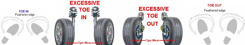
CHAPTER 9: TOE:
TOE IN, POSITIVE TOE, TOE (+), TOE (P) / TOE OUT, NEGATIVE TOE, TOE (-). TOE (N)

Toe angle is a tyre wearing angle and is adjustable

TOE is the parallelism position of the front or rear wheels when viewed from the top.
A simple method of visualizing TOE IN and TOE OUT is simply to look down at your feet, If the feet point inwards you are
standing in a TOE IN position and if your feet are pointing outwards you are standing in a TOE OUT position

Tyres last longer if they run in parallel paths. In other words they run parallel to the direction of travel, so you would expect
a Zero (0°) Degree setting to be best.

Zero (0°) setting of TOE is when the distance between the FRONT wheels, measured at A1 and A2 are the same length.
Zero (0°) setting of TOE is when the distance between the REAR wheels, measured at B1 and B2 are the same length.

However once the vehicle starts to move forward in its direction of travel and due to the “play” in the steering and
suspension components (Ball joints) the leading edges of the wheels are spread away from each other under rolling
stresses,
To compensate for this a slight static setting of TOE IN (positive +) of the wheel positions is common.
Referring to the above picture it means that the length of A1 is slightly shorter than length A2 on the FRONT wheels, this
practice is mostly applied to rear wheel drive vehicles.
Equally TOE IN means that length B1 is slightly shorter than length B2 on the rear wheels.

On front wheel drive vehicles, once the vehicle starts to move forward in its direction of travel, the “traction grip” (Pull in
under power) of the tyres tend to force the leading edges of the wheels inwards and so a practice of a static setting of the
wheels to a slightly TOE OUT (Negative -) position is common.
In this instance the length of A1 is slightly longer than length A2 on the FRONT wheels, being a TOE OUT situation
Equally TOE OUT on the rear wheels means that the length B1 is slightly longer than length B2
Toe is normally set on the front wheels by adjusting the Tie Rod Ends. Ideally the Tie Rod ends should be of equal length
and with the Steering spoke “centralised” adjustment begins on each individual wheel. The Toe settings as provided by
the specific vehicle manufacturer are used and an equal amount of toe adjustment is applied to each wheel. When
preferred specifications are given, TOE should be adjusted to the preferred settings. In the above picture (B) where the
Tie Rods are situated behind the suspension, adjust the Tie Rod to a longer Length to give a TOE IN effect or shorten to
give a TOE OUT effect.

HARMFULL EFFECTS OF TOO MUCH TOE
Toe is considered the most serious tyre-wearing angle. Its tyre wear appears as a feathered edge scuff
Excessive TOE IN will cause the tyres to wear unevenly on the outer edges of the tread width
Excessive TOE OUT will cause the tyres to wear unevenly on the inner edges of the tread width

--------------------------------------------------------------------------------------------------------------------------------------------------------------

CHAPTER 10: Toe out on Turns (T.O.O.T) – STEERING ANGLE

Toe out on turns (is a non-adjustable tyre-wearing angle):
Toe out on turns is also known as the Ackerman principal.

There are two aspects of wheel alignment that most people never
consider.
a) Driven wheels must rotate at different speeds and
b) The turning wheels must turn at different angles.

When a vehicle goes around a corner the outside wheels need to rotate
faster than the inside wheels. This is because the outer wheels have a
larger turning arc to complete as compared to the inner wheels which
need to make a sharper angle than the outside wheel because they will
be following a smaller arc
On the Driven axle the Differentials split power in such a way that the
powered wheels can turn at two different speeds.
On a trailing rear axle this is not necessary as the wheels roll “free”

The (steered) turning wheels face another problem, which is solved by
the Ackerman Principal.
If an imaginary line drawn through the steering knuckle’s axis of rotation
and the end of the steering arm intersecting the center of the rear axle,
then each front wheel would turn the correct angle in a turn and avoid
any tyre scrub. Although the Ackerman principal effect is not adjustable,
a good wheel alignment technician will measure it. If the car is out of
spec it means the steering arms or some other component of the front
suspension is bent and must be replaced
So “Toe out on Turns” or turning radius is when the inner front wheel turns shorter than the outer front wheel
creating a Toe Out condition when the vehicle is turned either to the left or right.
The design of the steering arm (tie rod ends) in relation to the wheel base of the vehicle provides this proper
relationship. Correct turning radius allows the front tyres to roll free on turns. For this reason turning radius will be
correct when the other alignment angles are correct, except when a steering arm is bent.

For interest sake the effect on the rear axle is that the “Spider gears within the crown wheel and pinion structure”
will slow down the rotational speed of the inner wheel to that of the outer wheel. This action allows the rear wheels
to follow the direction of the front wheels through a turn with minimal tyre wear.

Purpose of Toe out on Turns
Ø To prevent tyre side slip
Ø To prevent excessive irregular tyre wear
Ø To prevent tyre squeal on turns
Ø To diagnose bent suspension parts

HARMFUL EFFECTS OF INCORRECT TURNING RADIUS
Ø Excessive irregular wear of tyres on turns
Ø Squealing tyres on turns even at low speeds.

Toe out on turns is one of the most IMPORTANT angles in that it has a direct influence on the TOE IN or
TOE OUT settings of the vehicle.
To explain one needs to understand that a vehicle very rarely travels in a “TRUE STRAIGHT AHEAD” position
and therefore the front wheels are constantly deviating off the straight ahead due to the road surface and rolling
motion of the wheels.

Toe out on Turns is commonly of the value of 2° difference between the two front wheels when turned through
20°. With the inner wheel turned at 20° the outer wheel would indicate 18°. The exercise would be done for the
turn to the Left and for the turn done to the Right – (Normally measured on the scales of the front wheel
turntables)

Now this means that the TOE difference at 20° is 2°
So at a turn of 10° the difference is 1°
at a turn of 5° the difference is 1/2° or 30 minutes)
at a turn of 2½ ° the difference is 1/4° or 15 minutes)
at a turn of 1° the difference is 1/8° or 7 minutes)
at a ½° the difference is 1/16° or 3½ minutes

Equating this to millimeters on a 13” rim diameter wheel, ½ millimeter of toe is equal to 5 minutes of angle

Should the tyre Rod be bent or be of unequal length and cause the turning radius to vary by an additional 2° then
the change in TOE can change by as much as 15 minutes of angle or 1½ millimeters
This means that the linearity of the movement of the wheels through a 20° turn will have an additional error in
TOE of 15’ (1½ millimeters) either plus or minus. This in many instances can create a tyre wear pattern indicating
incorrect TOE settings, however when the static TOE is checked in a straight ahead position it conforms to the
vehicle manufacturers specification. Thus the fault is not in the TOE setting but in the mechanism of the
“Ackerman principal” and cannot be corrected through a simple TOE correction, worn parts will have to be
replaced or the Tie rod ends will need to be equalized.

Thus it can be deemed that the checking of TOE OUT ON TURNS (Steering Angle) is a confirmation of the
linearity of the TOE settings in compliance to the Vehicle Manufacturers specifications.
-------------------------------------------------------------------------------------------------------------------------------------------------------
CHAPTER 11: FRONT WHEEL SETBACK
Wheel offset is determined when the right front wheel is placed further back or further
forward than the left front wheel, when viewed through the centerline of the two wheels
If the right front wheel is placed further back than the left wheel the setback is said to be
NEGATIVE (-)
If the right front wheel is placed further forward than the left wheel the setback is said to be
POSITIVE (+)
Any setback value noted would indicate possible vehicle body / chassis damage and would be a valid assumption
provided both front wheels CASTER is of equal value and that there is no “Thrust angle” present on the rear axle

CHAPTER 11: FULL STEERING LOCK
                                                        This is also one of the most important angles that need to
                                                        be measured. It is normally done with the use of “Electronic
                                                        Front wheel turntables” that are linked to the front wheel
                                                        sensors by means of electronic data transmission cables.

                                                        The steering wheel is turned both to the maximum on both
                                                        left and right hand side until the wheels are stopped from
                                                        turning further by the “Bumper stops” This is normally done
                                                        to a turning angle of +/- 40°

Should the determined resultant values be within the Vehicle Manufacturers specification, then it is confirmation
that the linearity of all angles, (many of which are can only be checked / adjusted in a static straight ahead
position i.e. Toe, Camber and even Cater) are within specification from Straight Ahead position through to the
Maximum Steering Lock position
Should the Full Steering Lock angle values not be within the Vehicle Manufacturers specifications then in all
probability it is an indication of the existence of Chassis, Body, Suspension or Steering component damage.

The Importance of this Angle check is endorsed by the fact that it very rarely found that a vehicle will travel in a
true “Straight Ahead” position when the motorist is driving from one point to the next.
You can also read


