DODGE GRAND CARAVAN SECONDARY CONTROLS INSTALLATION GUIDE
←
→
Page content transcription
If your browser does not render page correctly, please read the page content below

DODGE GRAND CARAVAN
                                                               SECONDARY CONTROLS
                                                                 INSTALLATION GUIDE
                                                                                                     LAST UPDATED April 7, 2021

                                                                                                                                 REV: 03

                                                  2017© R.A.SH Tronics Ltd. All rights reserved.
Reproduction by any means, electronic, graphics (GUI) or mechanical, including photocopying, recording or by any information storage and retrieval
                 system or translation in whole or part is NOT PERMITTED without written authorization from R.A.SH Tronics Ltd.
TABLE OF CONTENTS
2 .............................................................................................................................................. TABLE OF CONTENTS
3 ............................................................................................................................................. APPLICABLE VEHICLES
3 ................................................................................................................................... TO OUR VALUED CUSTOMER
3 ....................................................................................................................................... CUSTOMER CARE CENTER
3 .............................................................................................................................................................. ABSTRACT
4 ........................................................................................................................................................ USEFUL HINTS
4 ......................................................................................................................Recommended installation procedure
5 ................................................................................................................................................ SYSTEM OVERVIEW
6 ..................................................................................................................... DESCRIPTION OF MAIN COMPONENTS
7 .............................................................................................. DESCRIPTION OF MAIN COMPONENTS CONTINUED
8 .................................................................................................................................. CAN-BUS GATEWAY MODULE
8 ........................................................ FUNCTIONS CONTROLED THROUGH CAN-Bus (NO PHYSICAL WIRING REQUIRED)
8 .............................................................................................................. FUNCTIONS CONTROLLED TROUGH RELAYS
9 ......................................................................................................................IDENTIFYING CAN-Bus CUT LOCATION
9 ................................................................................................................POWERING THE TOUCH-SCREEN MODULE
10 ................................................................................................................ CAN-Bus Powered gear selector module
10 ......................................................................................................BACKGROUND ON VEHICLE SHIFT POSITIONS
11 ................................................................................................................................. CAN-BUS GATEWAY WIRING
12 ...................................................................................................................................... Pushbutton start module
13 ....................................................................................................... KEY BARREL MODIFICATION PROCEDURE 2014
14 ....................................................................................................... KEY BARREL MODIFICATION PROCEDURE 2014
15 ....................................................................................................... KEY BARREL MODIFICATION PROCEDURE 2014
16 ....................................................................................................... KEY BARREL MODIFICATION PROCEDURE 2010
17 ................................................................................................................................... CRUISE CONTROL MODULE
18 ............................................................................................................. EGRESS MODULE FUNCTION DESCRIPTION
19 .............................................................................................................................. EGRESS MODULE INSTALLTION
20 ....................................................................................................................... INTELLIGENT VOICE SCAN MODULE
21 ...................................................................................... HEATING VENTILATION AND AIR CONDITIONING MODULE
21 ................................................................................................ MODIFYING THE DODGE DIGITAL HVAC MODULE
22 .....................................................................................................................................HVAC-1L RELAYS MODULE
23 .................................................................................................................................HVAC WIRING (MRB-712L)
24 ............................................................................................................................ SOLDERING ON HVAC BOARD
25 ......................................................................................................... SOLDERING ON HVAC BOARD CONTINUED
26 ......................................................................................................... SOLDERING ON HVAC BOARD CONTINUED
27 .................................................................................................................................. USING THE DODGE HVAC
28 .............................................................................................................................................VOICE SCAN SYSTEM
29 ............................................................................................................................................................ APPENDIX

                                                                                                                                                                        2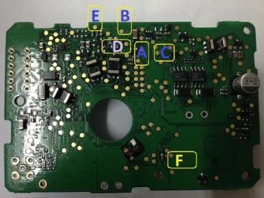
APPLICABLE VEHICLES

All the information and modules in this manual is applicable for the following vehicles, no change or update needed.

    1.   Chrysler Grand Voyager

    2.   Dodge Grand Caravan                                                       2008 to present

    3.   Lancia (EU)

TO OUR VALUED CUSTOMER

It is our intention to provide our valued customers with the best documentation possible to ensure successful use of
our products. We will continue to improve our publications to better suit your needs. Our publications will be refined
and enhanced, as new volumes and updates introduced. If you have any questions or comments regarding this
publication, please contact us.
We welcome your feedback.

CUSTOMER CARE CENTER

For additional application assistance, we urge you to consult with our experienced staff in our Customer Care Center.
Our Technical and Engineering staff has extensive test, research and development capabilities, and have assisted many
customers in solving unique design and application problems with standard and customized products.

                R&D Contact Address                                      US Support Contact Address

                                                                                 Clock Mobility
                                                                                6700 Clay Ave. SW
                  R.A.SH Tronics Ltd
                                                                             Grand Rapids, MI 49548
                rashtronix@gmail.com
                                                                                  (616) 698-9400
                                                                        technicians@clockmobility.com

ABSTRACT

This guide explains how to install the modules in the vehicle.

    v The information provided in the wiring diagrams is vehicle specific. It should be applied only to the vehicle
      indicated. Depending on the system you are installing, you may not install every harness.
    v Read modules placement first, it is very important to understand were to connect and fit the CAN-Bus based
      components to avoid future problems.
    v This manual becomes an integral part of the vehicle the system-installed in. You should therefore always keep
      it in the vehicle and pass on to the new owner, to safely use the systems.
    v R.A.SH Tronics Ltd reserve the right to make changes in product specifications at any time and without prior
      notice. The information in this manual, believed to be accurate and reliable. However, R.A.SH Tronics Ltd
      assume no responsibility for its use.

                                                                                                                         3
USEFUL HINTS

         v The electronic control board is an electrostatic sensitive device. Connect to a proper ground.
         v Use care when making electrical connections. Disconnect battery power prior to servicing.
         v When installing, check for any obstructions such as Gas tank, Gas lines, Wires, etc. before drilling or
           routing power cable.
         v For continued protection against fire hazard, replace only with the same type and rating of fuse.
         v Only allow R.A.SH Tronics factory trained technicians to install or service your system. If wear is observed
           on any part in the system, contact our US support.

RECOMMENDED INSTALLATION PROCEDURE

Before commencing the installation of this kit, it is recommended to follow these procedures, in short “plan your work,
keep your coffee cup away”:
    1. Install the LCD junction board and plug in the LCD, should be powered on and the sleep timer starts the down
        counting.
    2. Install the CANbus gear shifter module, no need to install the actuator at this stage, plug it to the junction
        board and wake up the van, the LCD must bake up and show the current gear position and some other
        information. Test the gear by pressing the foot brake and select any gear, the relay inside the module will click
        for a short time.
    3. Install the Start/Stop module, plug it to the junction board and test it without pressing the foot brake, the van
        must start. If not test yourself.
    4. Install the Multi-Function modules (marked A and B), remember to check that you received the correct
        resistors values so you never waste your time and our money (contact us immediately if you have any
        question, we are here to help). Test every function installed, meaning don’t wait for the full install and then
        test it all, for example, wire in the turn signals three wires and test it factory and on the LCD, then move the
        horn, wire it and test it, then the head lights and high beam and test them, do the same for all functions, this
        way if you run into a problem we know how to help.
    5. Install the HVAC module and the Parking brake, these are using very few wires, test factory switches and on
        the LCD. If a function is not working, just reset the van by disconnecting the main battery.
    6. Install the powered mirrors module, this module needs many wires as can be seen in the diagram, so it is very
        important to plan this install for successful results, follow the recommendations below:
        a. Mount the module in the driver door so the wires may not short or touch by mistake.
        b. Power the module on TB1 and plug the module to the junction board as per diagram.
        c. Test the module by selecting the mirrors screen and touching the mirrors symbols, you should hear the
             internal relays clicking, if so, 1st success.
        d. Start with the driver side mirrors (motors), cut one wire at a time and mate it to the terminal block, test
             the system, factory switches only, the screen will activate the mirrors at this stage, if all factory works ok,
             then 2nd success. Do this for every single wire, so three for driver side and another three for passenger
             side.
        e. Do the jumpers wires as per diagram and test the system from LCD only (factory switches already
             previously tested), if all works, 3rd success and job is behind.
    7. Install the Driver door module (windows/ door locks), this module is very tricky to install, it is very
        recommended to contact a mobile repair shop to solder the wires on the OEM board so you can safely mate
        them to the module. You must take extra precautions on these three wires, if touched to the power, contact
        Chevy dealership to get a new module and remember to throw this one.

                                    CONTACT US IF YOU NEED HELP AND GOOD LUCK

                                                                                                                               4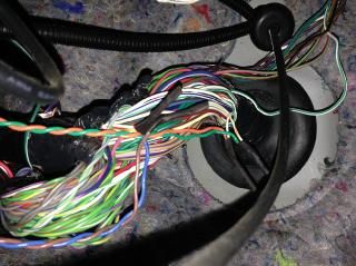
3.5" LCD TOUCH Part#: IVS-1X
Part#: EPB-2X MODULE Intel ligent In Motion Voi ce Sca n Module
ELECTRONIC PARKING
BRAKE MODULE
LIN ca bl e
SYSTEM OVERVIEW
Part#: EPB-2XL
LOW-EFFORT
SWITCH #1
1 6
Part#: VAC-601X
LOW-EFFORT
CANbus gateway, Totally integrated module SWITCH #2
MRB-612L
Docking station, EGRESS and more
VOICE SCAN
SPEAKER
LIN cable
Analog Cruise Control
module
6 1
Part#: VAC-12X CGVT LIN ca ble
CANbus_1
CANbus_2
Part#: SS-1L CGV
See Manual for a List of Supported Functions on CANbus
Additional Functions using relays LIN cable Mountig
POWER GEAR SELECTOR Screws
CRUISE CONTROL/ HAZARDS
COMPUTER DATA
LINES SYSTEM EGRESS/ DOCKING STATION
LIN ca ble 4 J1
CONNECTOR FOR INPUT LIN junction box P/N: STA-35-LJ
Part#: RID-1L Part#: JID-1L DEVICES ONLY 1
Sta rt/ Stop Sys tem
DODGE GRAND CARAVAN Totally Integrated System, components
Size CAGE Code DWG NO Rev
A4 059-957-746 A
Scale Sheet
1 of 1
5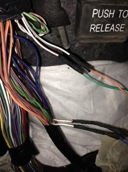
DESCRIPTION OF MAIN COMPONENTS

DRIVEIN STA-35-xxx DISPLAY

Through this 3.5” single touch screen displays you can
control all operation and programming functions for the
DRIVEIN system.
All secondary functions are also controlled and
programmed through the display. It’s location in the
vehicle will vary, depending on the system set-up and
mounting options for the driver.
Most secondary functions can be remotely operated
from other devices (In motion voice scan, five buttons
Round Touchpad, five ways joystick and do it yourself
switches), depending on the customer needs. Refer to
the Drivein Operation and Programing Manual for
further details.
VEHICLE INTERFACE MODULE

Through this dual CAN-Bus gateway module, which is
connected to the vehicle communication network, it is
possible to control almost all secondary functions like
Driver/passenger window, turn signals, horn and many
more. It is connected to the OBD harness and to another
CAN-Bus harness in the vehicle.
It is also used to collect real time information and update
the LCD display.

ENGINE START/STOP MODULE

This module is used to override the OEM start stop
system. It is designed to be directly attached to the OEM
high current harness using the quick-fit terminals of the
OEM harness. No need to solder, just remove the OEM
wires from the connector and plug them as per wiring
diagram provided in this manual for your specific vehicle.

UNIVESAL FUNCTIONS MODULE

A programmable relay box built in 12 powerful relays.

    •    Docking station (Q’STARINT, EZ-LOCK)

    •    Hazard warning lights

    •    Bi-Directional actuator and many more

    •    HVAC controlling the digital HVAC module

                                                              6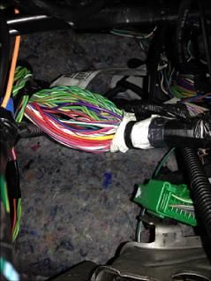
DESCRIPTION OF MAIN COMPONENTS CONTINUED

INPUT DEVICES: RID-1L round input device.

It has five buttons blue lighted with universal automotive
symbols. It should be mounted within reach of the
driver.

It is designed to access the in-motion functions like turn
signals and horn.

Five big buttons easy to use, small size.

INPUT DEVICES: JID-1L joystick input device.

It is a five ways mini-joystick, very small size, easy to use
can be mounted within easy reach of the driver.

 It is designed to access the in-motion functions like turn
signals and horn.

INPUT DEVICES: DIY-1L twelve momentary switches
input device.

This module is used to access up to twelve functions in
the vehicle using low effort switches. Can be mounted
under the steering and hardwired to different switches
located within easy reach of the driver.

                                                                7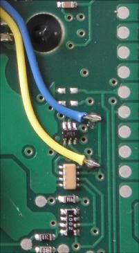
CAN-BUS GATEWAY MODULE

The R.A.SH Tronics CANbus gateway is a very powerful device, it allows access to
many of the vehicle functions without the need to remove plastic parts or
additional external relays.
The CAN Gateway Module connects to the Drivein LCD touch screen on the LIN
junction port and to the vehicle’s CAN system to operate the secondary functions,
listed below in the table. It is also responsible to wake up the touch screen and put
it to sleep after locking the vehicle.
THESE SECONDARY FUNCTIONS WILL REQUIRE NO FURTHER PHYSICAL WIRING,
which will greatly reduce the amount of installation time and increase reliability.
There are, however, a few secondary functions that will require physical wiring. These functions are not listed in the
table below but in the pages to follow. For this module to integrate inside this vehicle, the OEM CANbus wires must be
cut, the module is connected between the two CANbus wires that should be cut, see picture A next page, the OEM
CANbus wires are located on the lower left dash panel in the driver’s area. The Gateway module itself is typically
installed behind the center console area and secured to vehicle using the mounting tabs on the module. The CAN
Gateway Module is responsible to wake up and put to sleep of all system components, so be sure to connect the wires
utilizing proper soldering practices according to SAE J1292.

FUNCTIONS CONTROLED THROUGH CAN-BUS (NO PHYSICAL WIRING REQUIRED)

 Driver Door Functions:
     1. Driver window: Up/ Down.                                     Turn signals with steering position canceling and
     2. Passenger window: Up/ Down.                                  indication on dashboard same as manufacturer.
     3. Driver Mirror: Up/ Down/ Left/ Right.
     4. Passenger Mirror: Up/ Down/ Left/ Right.
                                                                     Full lights:
 Front Wipers                                                              1. Taillights (parking lights).
     1. Intermittent wipe/ Normal wipe/ Rapid wipe.                        2. Head lights (Main lights).
     2. Front wash.                                                        3. High beam.
 The OEM auto wipers not canceled.                                         4. Flash.

 Horn                                                                Interior lights on/Off

 Rear Wipers                                                         Sliding doors Open/Close:
     1. Intermittent & Normal wipe                                        1. Driver side.
     2. Rear wash                                                         2. Passenger side.

 Heating Ventilation and Air Conditioning                            Doors Lock/Unlock
     1. Temperature: Hot/ Cold
     2. AC: On/ Off with OEM Led indication
     3. Air flow with indication:
              a. Front
              b. Front/ Feet
              c. Feet
              d. Feet/ Defrost
              e. Defrost

FUNCTIONS CONTROLLED TROUGH RELAYS

                            SOLDERING ON ORIGINAL MANUFACTURER BOARDS REQUIRED

 PUSHBUTTON START SYSTEM                                     DOCKING STATION
 HAZARD WARNING LIGHTS

                                                                                                                         8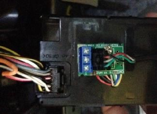
IDENTIFYING CAN-BUS CUT LOCATION

Use maximum care to find the exact cut location in the vehicle. The twisted CANbus wires can easily be found under the
steering inside the harness going out through the grommet behind the park brake bracket, to the engine compartment.

Pictures below pointing to the same location

POWERING THE TOUCH-SCREEN MODULE

There are two ways of powering the screen, depends on if the system is equipped with an EGRESS module or not, figure
A is showing an installation without the EGRESS module, so you just need to wire the red and black to a battery power,
it is always a good practice to separate the ground wires into different locations in order to minimize failure if a GND
screw is loose.
                                                                             To LCD module
For the second wiring option, please follow the EGRESS
module wiring diagram.

                                                                                         4

                                                                                         1

                                                                          LIN junction box P/N: STA-35-LJ   F1
                                                                                                                 5A FUSE

                                                                                             RED (BAT)
                                                                                             BLK (GND)
                                                                                 6   5   4
                                                                                             J1
                                                                                 3   2   1
                                                                                             Pow er

                                                                          LCD Junction Box Connector

                                                                                                            VEHICLE PRIMARY BATTERY

                                                                                                                                  9
CAN-BUS POWERED GEAR SELECTOR MODULE
This new R.A.SH Electronics powered gear selector uses the CAN-Bus network information to function, making it easy to
fit inside any modern vehicle. Since the CAN-Bus information is very reliable, shifting does not rely on Potentiometer
position or the voltage measured out of it and does not require any programming to install. Check wiring diagrams
below.
This new concept of powered gear selector brings the vehicle safety to a higher level, since the system collects in real
time the vehicle speed combined with the foot brake information. For example: NO SHIFTING is possible if the Reverse
button is pressed while the vehicle is driving at a certain speed, even if the foot brake is slightly pressed. The shifter is
easy to operate by just pressing the gear buttons shortly, not using any Long/Short press mode. The OEM gear cable is
attached to a 52mm actuator which is linked to the controller module.
BACKGROUND ON VEHICLE SHIFT POSITIONS
What is important to understand before proceeding is the actual mechanical position of the vehicle’s shift cable as it
moves from PARK to the lower DRIVE gears. In almost every vehicle, the PARK position is when the vehicle’s cable is
completely retracted or pushed all the way into the outer housing. You can manually cycle thru the gears by holding the
outer cable housing stationary with one hand and pulling on the eye of the cable with the other. As you pull, you will
feel the cable move approximately 9mm and stop at a detent. This is the next gear selection. So with the cable
completely retracted in the PARK position, the next detent is REVERSE, then NEUTRAL, DRIVE, D3, D2, and finally L. The
number of lower gears will vary slightly depending on the vehicle.
J3: Park Position Select J3: Park Position Select
Yellow(A) Yellow(A)
Ds1 J3, Open (Manufacturer default) Ds1 J3, Shorted
Black(B) Black(B)
J1 J2 J1 J2
J3 J4 J3 J4
Settings Settings
P R N D S S D N R P
Actuator Connector
Actuator connector
Ds1 female Black(B)
Settings
J1 J2
Yellow(A)
BLK 16AWG
RED 16AWG
J3 J4
Actuator connector
male
Part description
Part#: 609 002 115 121 8 7 6 5
J1 Female
WR-PHD_2.54mm_Jumper Part#: RSM-50-xxxx internal view 4 3 2 1
RSM-50-xxxx Actuator Part#: DS1217A08 462
Com
Sw1
Sw2
Sw3
Sw4
Sw5
Black with pullback_1x2p
TB1
CAN-Bus powered gear
Ds1 Ds1 Ds1 selector module
J1/J2: Park position nudge.
J1 J2 J1 J2 J1 J2
Ds1 J3 J4 J3 J4 J3 J4
J3: Park Position Select
J1 J2 0.1Sec 0.2Sec 0.3Sec
J3 J4
IMPORTANT
Dew to the actuator control accuracy, in some vehicles the Park position
Settings needs some nudge in order to be able to remove the OEM key. Set the
nudging time as needed.
Part#: RSM-50-xxxx
R.A.SH Tronics Ltd Powered Gear Selector Actuator Positioning
(T) +972-48517656 Size CAGE Code DWG NO Rev
(F) +972-48523339 A4 059-957-746 RSM-50-xxx A
rashtronix@gmail.com
Scale Sheet
Friday, August 25, 2017 2 of 3
10DIY sw itches using terminal blocks
TB1
Actua tor connector
Sw1
Sw2
Sw3
Sw4
Sw5
femal e Ds1
Sw. Com.
J1 J2
J3 J4
Settings
5
BLK 16AWG
RED 16AWG
1
F1
CAN-BUS GATEWAY WIRING
J1 +12V (BAT) 5A FUSE RED
Pow er/CAN connector
GND BLK or BRN
J?
8 7 6 5 Input Device
J1 Female
4 3 2 1
VAC-12LCC
TB1 Front
Terminal Block
GND
ECU CAN-Bus
MDL CAN-bus
FIRE WALL
BLU
WHITE/GREY
BRN
GRN
ORG
D265 WHT/GRY
COMPUTER DATA
WHITE/ORANGE
D264 WHT/ORG LINES SYSTEM Sw ?
TOTALLY INTEGRATED POWER MODULE
(LEFT SIDE OF ENGINE COMP)
Park Position
Sw ?
R/N Position
Control board bottom side
Ap p l i c a b l e V e h i c l e s: Sw ?
MDL: shorted
CHRYSLER GRAND VOYAGER
D Position
DODGE GRAND CARAVAN ECU: shorted
LANCIA (EU m odel)
R.A.SH Tronics Ltd Chrysler Grand Voyager, CAN-Bus stand alone gear selector
© 2016 R.A.SH Troni cs Ltd. Al l ri ghts res erved. Reproducti on by a ny mea ns , el ectroni c, (T) +972-48517656 Size CAGE Code DWG NO Rev
graphi cs (GUI) or mecha ni ca l , i ncl udi ng photocopyi ng, recordi ng or by a ny i nforma ti on (F) +972-48523339 A4 059-957-746 RSM-50-xxx A
s torage a nd retri eva l s ys tem or tra ns l a ti on i n whol e or pa rt i s NOT PERMITTED wi thout rashtronix@gmail.com
wri tten a uthori za ti on from R.A.SH Troni cs Ltd IL. Scale Sheet
Friday, November 24, 2017 SW: RSM-50-CGV.hex 2 of 3
11PUSHBUTTON START MODULE
Depending on your van model and year, the key barrel internal board may be different, two start stop system available
sharing the same board with different software, This (SS-1L-CGV) start stop module is linked to the LCD touch controller
and through the CANbus network constantly updated with the vehicle status of the
powered gear selector module. Modifying the OEM start stop module in this vehicle
requires key barrel removal and delicate work inside the OEM board. Please follow
the instructions below carefully, as we accept no responsebility for any damage to
any part of the system or the vehicle due to installation errors, mistakes or oversight
by dealer personnel.
If you think this is too difficult to do, we urge you to
contract this job out to our US support. We thank you in
advance for making this serious consideration.
Picture A
Step 1 Step 2
12KEY BARREL MODIFICATION PROCEDURE 2014
After the key barrel removed, carefully open the back cover using a flat head screw driver.
Picture C
Step 1
Key barrel internal board after removing the
back cover. Confirm this board is what you
have in your vehicle.
Step 2
Desolder the five big round pads marked in
yellow.
Before lifting out the board, confirm all five
pins 100% free of solder by moving each one
with your finger, then remove the board.
There are nothing that can be damadged
under the board by lifting it out.
Use reasonable force when bending the
white clips on the sides in order to release
the board.
Step 3
OEM key barrel bottom view.
13KEY BARREL MODIFICATION PROCEDURE 2014
Step 4
Identifying the round pads to be used for
soldering the colored wires supplied with the
kit.
The SS-1L-CGV board supplied with 8 colored
wires, follow the instructions below to solder
all wires on the OEM board. Use a good
quality soldering iron, set it to 680⁰F and
good quality solder. The on board round
pads are small but clear and easy to solder
on top.
Step 5
Drill a 5mm hole in the key barrel bottom
cover and insert the 8 colored wires inside
the hole so you can solder the wires and put
back the key barrel to its original state.
Step 6
1. Solder the “WHITE” wire to the
round pad marked (A).
2. Solder “BLUE” wire to the round
pad marked (B).
3. Solder the “YELLOW” wire to the
round pad marked (C).
4. Solder the “GREEN” wire to the
round pad marked (D).
5. Solder the “GREY” wire to the round
pad marked (E).
6. Soder the “PINK” wire to the round
pad merked (F).
If you mixed these wires by mistake, you
will not damadge anything but you get a
message (DAMGED KEY), just repeate the
previous steps and put the wires correctly.
14KEY BARREL MODIFICATION PROCEDURE 2014
Step 7
The “RED” and “BLACK: wires are very
critical, they are the 12V power. Double
ckeck your woldering to confirm no shorts
made.
1. Solder the “RED” wire to the
capacitor as you see in the picture
to the right.
2. Solder the “BLACK” wire to the
capacitor as you see in the picture
to the right.
3. Put back the board as it was before
and solder the five big pads as can
be seen in Step 1.
Step 8
Put back the key barrel and plug it back to
the OEM harness.
Final step
The OEM key must be fixed to the key barrel in zero distance to the Immobilizer coil as seen in the pictures below.
• Use a good quality electric tape for fixing so it last for a long time.
• The key fob battery can be removed, it does not affect the immobilizer.
If you get a “DAMAGED KEY” message on the dash board, check the key mounting, may be it needs to be close to
the Immobilizer coil.
Read the Drivein user manual, using the start stop system.
15KEY BARREL MODIFICATION PROCEDURE 2010
16#5 VIO/BRN (GND) 21
#6 VIO (SIG 1) 23
#4 VIO/ ORG(SIG 2) 22
STEERING CONTROL MODULE POWER TRAIN CONTROL MODULE
(ON STEERING COLUMEN) (LOWER LEFT END OF ENGINE
COMP)
CRUISE CONTROL MODULE
J1 6 5 4
Pow er 3 2 1
F1
Red (BAT)
IGN
5A IDENTIFYING CRUISE WIRES LOCATION AND HARNESS
Black (GND)
GND
J1
1
4
Pow er
Mounting bracket
TP
R.A.SH Tronics Ltd Chrysler Grand Voyager, Cruise Control Wiring
© 2017 R.A.SH Troni cs Ltd. Al l ri ghts res erved. Reproducti on by a ny mea ns , el ectroni c, (T) +972-48517656 Size CAGE Code DWG NO Rev
graphi cs (GUI) or mechani cal , i ncl udi ng photocopyi ng, recordi ng or by any i nformati on (F) +972-48523339 A4 059-957-746 VAC-601L A
s tora ge a nd retri eval s ys tem or tra ns l ati on i n whol e or pa rt i s NOT PERMITTED wi thout rashtronix@gmail.com
wri tten a uthori za ti on from R.A.SH Troni cs Ltd IL. Scale Sheet
Tuesday, December 05, 2017 2 of 3
17EGRESS MODULE FUNCTION DESCRIPTION
The EGRESS module or emergency battery module, is designed to monitor the main and the Prima
18USE COPPER CABLE LUGS
100A Solenoi d (Mus t be mounted a s 86 85
clos e as pos s i bl e to the AUX ba ttery) Mul ti pl e momentary s wi tches a re
pos s i ble, i ns i de & outs i de of the Va n.
POWER
GROUND
When the main battey is flat, press and
30 87 (CHASISS) Internal Externa l
hold the switch to wake up the system
and engage the AUX battery. Switch Swi tch
4AWG 4AWG
To vehicle electrical
system
Power Distribution
System
To LCD module
To Vehicle
EGRESS MODULE INSTALLTION
Starting/Charging
System
J1 Pow er
POWER
GROUND 6 5 4
4AWG
4AWG
(CHASISS) 3 2 1
BLU/YEL (18AWG)
GRY (20AWG) to pin# 86
BLU/WHT (18AWG)
AUX BATTERY
VEHICLE PRIMARY EGRESS TOUCH SYMBOL LCD Junction Box
POWER GROUND BATTERY Connector
(CHASISS)
Pres s & Hold to al terna te F1
ADD 5A FUSE
F2
(Dis abl e/ Enabl e) the 5A FUSE
a utoma ti c cha rging function.
8 7 6 5
J2 YEL (20AWG)
4 3 2 1
AXB-1X
EGRESS MODULE
Mus t be mounted i ns ide the
vehicle
Ca ble s uppl ied with the kit
J2
5
1
IDENTIFYING THE AUX BATTERY MODULE R.A.SH Tronics Ltd EGRESS Module Connections
4 Gauge AWG Battery Cable has an amperage capacity of 100 amps at a (T) +972-48517656 Size CAGE Code DWG NO Rev
cable length of 9.4 feet. Don't even think to over lengthen the cable. It is (F) +972-48523339 A4 059-957-746 Part #: AXB-1 A
rashtronix@gm ail.com
recommended to shorten the battery cables as much as possible. Scale Sheet
Monday, March 29, 2021 1 of 3
19Speaker inside the driver door
THIS DIAGRAM IS NOT A WIRING DIAGRAM, IT IS
SHOWING THE SYSTEM PINOUT AND CONCEPT.
VIO/YEL (Spk +)
GRN/ORG (Spk -)
VIO (Radi o +)
Driver door speaker wires
GRN/BRN (Ra di o -)
12 11 10 9 8 7
INTELLIGENT VOICE SCAN MODULE
If the extended functions are not
Relays
used, power the module from the 6 5 4 3 2 1
Ignition instead of BAT. J2 Female
Immedea te functions (us ing three s wi tches F1
on hea d res t or foot) 5A FUSE
Optional, do not add if not required.
GRN (SW4)
BLU (SW2)
ORG (SW1)
Left Turn
BRN (SW3)
BLK (GND)
D1 (1N5406)
Extended Functi ons Sw2
RED (BAT)
BLK (GND)
Horn
D1 (1N5406)
Right Turn
Ba s i c Functions Sw1
IDENTIFYING THE VOICE SCAN MODULE
R.A.SH Tronics Ltd Intelligent Voice Scan Module (Concept & Pinout)
© 2021 R.A.SH Tronics Ltd. All rights res erved. Reproduction by any mea ns , el ectroni c, gra phi cs (T) +972-48517656 Size CAGE Code DWG NO Rev
(GUI) or mecha nica l , i ncl uding photocopyi ng, recordi ng or by a ny i nforma ti on s tora ge a nd (F) +972-48523339 A4 059-957-746 IVS-1X A
retrieva l s ys tem or tra ns l ation i n whol e or pa rt is NOT PERMITTED without wri tten a uthori za ti on rashtronix@gmail.com
from R.A.SH Tronics Ltd IL. Scale Sheet
Wednesday, April 07, 2021 1 of 1
20HEATING VENTILATION AND AIR CONDITIONING MODULE
Depending on your Dodge model and year, the HVAC module may be different. The information below describes
modifying the HVAC module appearing in the picture. If this is not your case, please contact our US support.
In order to safely get this system to work and avoid
damaging the OEM board, we strongly recommend
using rubber gloves and/ or a Ground Discharge
Wrist (read more in Appendix).
The HVAC module modification requires to
interfere inside the OEM board and solder some
wires that are not provided. The wires should be
thin and as short as possible, the MRB-712L HVAC
module must be placed as close as possible to the
OEM HVAC unit, so we recommend attaching the
MRB-712L to the back side of the HVAC unit.
The OEM HVAC module supports dual zone climate control, while our module is designed to control only the driver
zone (single zone). But if you use the SYNC button, you can easily control the dual zone; read more below.
MODIFYING THE DODGE DIGITAL HVAC MODULE
If this HVAC module is installed in your vehicle, then a special jumper inside the CAB bus gateway must be shorted, see
Picture A red wire.
REMOVE THE PLASTIC ON THE DASH CENTER
HVAC DIGITAL MODULE HVAC REMOVAL
Picture A, (CANBus module)
Settings
Sw5
J1 J2
J3 J4
Ds1
Sw4
Sw3
Sw2
Sw1
Sw. Com.
TB1
21HVAC-1L RELAYS MODULE
Shortl y pres s
touch button
RED RLY7 RLY1
87A 87A
Pres s a nd
the touch
Hold the
button 30 30
BRN 87 87
RLY8 RLY2
87A 87A
30 30
87 87
RLY3
87A
30
BOARD BOTTOM VIEW
87
RLY4
87A
30
E1B 87
E2B E1A
E2B RLY5
E2A E2A 87A
30
BLU
YEL
87
RLY6
BLK (GND) 87A
30
GND 87
RED (+12V) 12V
POWER
BLK
87A
30 WHT
87
Bl a ck ca bl e to junction box
RLY1
BOARD TOP VIEW
87A
Input Device
30 PPL
87
J?
RLY2
RLY6
87A
BOARD BOTTOM VIEW
30 BLU
87
RLY5
RLY3
87A
RLY4
30 GRY
87
RLY4
RLY3
87A
30
87
RLY8
RLY2
YEL
RLY5
87A 87A
RLY7
RLY1
RED 30 30
87
BRN 87 GRN
RLY6
22Shortly press symbol
Press & Hold symbol
IGN
GND
TB2 TB3
TB1 YEL
R187a R230
WHT GRY
R187 R287
HVAC WIRING (MRB-712L)
Part#: MRB-712L
BLK (COM)
R130 R287a
SYNC
R387a R430
VIO
R387 R487
R330 R487a
R587a R630
BLU
R587 Touchpad connector R687 FUTURE
R530 R687a
RED
R787a R830
BRN
R787 R887
GRN
R730 R887a
Dip Sw itches?
ON
TB4 TB5
GRN
R_30 R_30
R_87 R_87a
1 2 3 4 5 6 7 8
FUTURE
R_87a Vehicle Select R_87
WHT
R_30 R_30
Fan Speed Encoder
R.A.SH Tronics Ltd Universal HVAC Module, DODGE HVAC wiring
© 2016 R.A.SH Tronics Ltd. All rights reserved. Reproduction by any means, electronic, graphics (T) +972-48517656 Size CAGE Code DWG NO Rev
(GUI) or mechanical, including photocopying, recording or by any information storage and (F) +972-48523339 A4 059-957-746 Part#: MRB-712L CGV A
retrieval system or translation in whole or part is NOT PERMITTED without written rashtronix@gmail.com
Scale Sheet
authorization from R.A.SH Tronics Ltd IL. Tuesday, December 12, 2017 1 of 3
23SOLDERING ON HVAC BOARD
Air flow button first wire
Grey
And SYNC button second wire
Air flow button second wire
Yellow
OFF button first wire
Red
OFF button second wire & Fan speed encoder common
Brown
24SOLDERING ON HVAC BOARD CONTINUED
Temperature: Hot/ Cold/ AC and SYNC button common,
first wire.
Black
Temperature Cold button second wire
Violet
Temperature Hot button second wire and Auto button
White
AC button second wire.
Blue
25SOLDERING ON HVAC BOARD CONTINUED
Auto button first wire.
Green
FAN SPEED ENCODER MOUNTING AND WIRING
NOTES
26USING THE DODGE HVAC
This is the multifunction control touch button: press repeadetdly to toggle through the
settings and manually choose one of the following air distribution modes (Panel, Floor,
Panel and Floor,Floor and Defrost).
Press and Hold this button to select the SYNC mode, this mode is used to select singel or
dual zone.
This touch button can do three functions:
Shortly press to decreas the fan speed one step.
Press and hold to constantly decrease the fan speed until button released. If the button
continue to be depressed for more than 2 seconds, the HVAC will be turned off.
Shortly press this touch button to turn on the HVAC and increase the fan speed one step.
Press and hold to constantly increase the fan speed until the button released of the
maximm speed reached.
Shortly press this touch button to toggle the AC “Air conditioning” on or off.
Press and hold to engage full automatic operation
Shortly press this touch button increase (Hot) the tempereture one step.
Press and hold to constantly increase the temperature until the button released or the
maximm temperature reached.
Shortly press this touch button decrease (Cold) the tempereture one step.
Press and hold to constantly decrease the temperature until the button released or the
maximm temperature reached.
27In Motion box P/N: IMID-1L
LCD connector
1
4
VOICE SCAN SYSTEM
Volume increase
4
Volume decrease
Extended function
1 select
Extended function select
Short press: Play music
Volume decrease
Five ways joystick
DIY Sw itch
Green (20AWG) Sw itch
Volume increase
F1 SW PUSHBUTTON
Green (20AWG) Com.
RED RED (20AWG)
J1-6 BAT/ IGN
The switch is not supplyed. Add
The red wire can be powered by 5A FUSE momentary switch if not used with
BAT or switch supply IGN. 6 5 4 J1 Female the Joystick.
3 2 1
Pow er
BLACK (20AWG)
J1-3 GND
SPEAKER (-)
Speaker supplyed as part of the system.
So no need to add spearer.
SPEAKER (+)
R.A.SH Tronics Ltd IN MOTION, INTELLIGENT VOICE SCAN SYSTEM
© 2017 R.A.SH Tronics Ltd. All rights reserved. Reproduction by any means, electronic, (T) +972-48517656 Size CAGE Code DWG NO Rev
graphics (GUI) or mechanical, including photocopying, recording or by any information (F) +972-48523339 A4 059-957-746 IMID-1L A
storage and retrieval system or translation in whole or part is NOT PERMITTED without rashtronix@gmail.com
Scale Sheet
written authorization from R.A.SH Tronics Ltd IL. Wednesday, September 20, 2017 1 of 1
28APPENDIX
SPECIFICATION
The following chart lists the standard wire colors and their corresponding abbreviations that will be used for the
installation of all R.A.SH Tronics Ltd products.
WIRE COLOR COLOR ABBREVIATION WIRE GAUGES CURRENT RATING
BLACK BLK 0.3mm AWG22 5A
BROWN BRN 0.5mm AWG20 7A- 13A
RED RED 0.85 mm AWG18 9A-17A
ORANGE ORG 1.28 mm AWG16 12A-22A
YELLOW YEL 2 mm AWG14 16A-30A
VIOLET VLT 3 mm AWG12 21A-40A
GRAY GRY
WHITE WHT
TAN TAN
PINK PNK
PURPLE PPL
BLUE BLU
LIGHT BLUE LT BLU
DARK BLUE DK BLU
GREEN GRN
LIGHT GREEN LT GRN
DARG GREEN DK GRN
SOLDERING SPECIFICATION
• Soldering Method- The soldering method
shown at right is offered for general
information. Depending on the connection
desired, other methods may be used.
• You must use Wrist Strap Ground when
soldering on OEM boards like key barrels/
HVAC or any other.
• We accept no responsibility to any damage to
OEM boards/ modules not soldered by us.
29You can also read