ANCAP Test Protocol. AEB Car-to-Car Systems v3.0.2 - JANUARY 2020
←
→
Page content transcription
If your browser does not render page correctly, please read the page content below
ANCAP Test Protocol.
AEB Car-to-Car Systems v3.0.2

JANUARY 2020
PREFACE

During the test preparation, vehicle manufacturers are encouraged to liaise with ANCAP and to observe the
way cars are set up for testing. Where a vehicle manufacturer feels that a particular feature should be altered,
they should raise this with the ANCAP assessor present at the test, or in writing to the ANCAP Chief Executive
Officer if no assessor is present. ANCAP will consider the matter and at their sole discretion and give direction
to the test facility.

Vehicle manufacturers warrant not to, whether directly or indirectly, interfere with testing and are forbidden
from making changes to any feature that may influence the test, including but not limited to dummy positioning,
vehicle setting, laboratory environment etc.

Illustrations in this protocol are reproduced from Euro NCAP publications, and therefore show Euro NCAP
markings on left-hand-drive vehicles. Where relevant, the layouts depicted should be adapted to right-hand-
drive application.

 VERSION PUBLISHED DETAILS
 2.0 July 2017 First version of ANCAP protocol.
 2.0.1 December 2017 Amendments to s6.1.1, 8.1.2, 8.2.4.
 3.0.1 April 2019 New version of protocol for 2020, introducing junction scenarios
 and other changes.
 3.0.2 July 2019 ECE method added to PBC Definition. Corrected references in s8.2.6.

 © COPYRIGHT ANCAP 2019
 This work is the intellectual property of ANCAP with
 certain content reproduced with the permission of
 Euro NCAP. A licence is granted for this material to
 be shared for non-commercial, educational purposes,
 provided this copyright statement appears on the
 reproduced materials and notice is given that the
 copying is by permission of ANCAP. To disseminate
 otherwise or to republish will be considered a breach
 of intellectual property rights.

 DISCLAIMER.
 ANCAP has taken all reasonable care to ensure that the information published in this protocol is
 accurate and reflects the current technical decisions taken by the organisation. In the event this
 protocol contains an error or inaccuracy, ANCAP reserves the right to make corrections and determine
 the assessment and subsequent result of the affected requirement(s).
AUSTRALASIAN NEW CAR ASSESSMENT PROGRAM (ANCAP)

 TESTING PROTOCOL – AEB Car-to-Car Systems
Table of Contents

1 INTRODUCTION 1
2 DEFINITIONS 1
3 REFERENCE SYSTEM 3
 3.1 Convention 3
 3.2 Lateral path error 4
 3.3 Lateral overlap 4
4 MEASURING EQUIPMENT 5
 4.2 Measurements and Variables 5
 4.3 Measuring Equipment 5
 4.4 Data Filtering 5
5 GLOBAL VEHICLE TARGET 6
 5.1 Specification 6
6 MANUFACTURER DATA 7
 6.1 Manufacturer Supplied Data 7
 6.2 Absence of Manufacturer Data 8
7 TEST CONDITIONS 9
 7.1 Test Track 9
 7.2 Weather Conditions 10
 7.3 Surroundings 10
 7.4 VUT Preparation 11
8 TEST PROCEDURE 13
 8.1 VUT Pre-test Conditioning 13
 8.2 Test Scenarios 14
 8.3 Test Conduct 17
 8.4 Test Execution 18
ANNEX A BRAKE APPLICATION PROCEDURE 20
ANNEX B Emergency Steering Support 23
1 INTRODUCTION

This protocol specifies the AEB Car-to-Car test procedures, which are part of the
Safety Assist assessment. To be eligible to score points for AEB CCRs (10-50km/h),
a good Whiplash score must be achieved for the front seat.

For AEB Car-to-Car, the system is tested in three scenarios (CCRs, CCRm and
CCRb). For this type of AEB system, both the AEB and FCW functionality is assessed.
The turn-across-path scenario (CCFtap) is only assessed for AEB performance.

2 DEFINITIONS

Throughout this protocol the following terms are used:

Peak Braking Coefficient (PBC) – the measure of tyre to road surface friction based
on the maximum deceleration of a rolling tyre, measured using the American Society
for Testing and Materials (ASTM) E1136-10 (2010) standard reference test tyre, in
accordance with ASTM Method E 1337-90 (reapproved 1996), at a speed of 64.4km/h,
without water delivery. Alternatively, the method as specified in UNECE R13-H.

Autonomous Emergency Braking (AEB) – braking that is applied automatically by
the vehicle in response to the detection of a likely collision to reduce the vehicle speed
and potentially avoid the collision.

Forward Collision Warning (FCW) – an audio-visual warning that is provided
automatically by the vehicle in response to the detection of a likely collision to alert the
driver.

Dynamic Brake Support (DBS) – a system that further amplifies the driver braking
demand in response to the detection of a likely collision to achieve a greater
deceleration than would otherwise be achieved for the braking demand in normal
driving conditions.

Autonomous Emergency Steering (AES) – steering that is applied automatically by
the vehicle in response to the detection of a likely collision to steer the vehicle around
the vehicle in front to avoid the collision.

Emergency Steering Support (ESS) – a system that supports the driver steering input
in response to the detection of a likely collision to alter the vehicle path and potentially
avoid a collision.

Car-to-Car Rear Stationary (CCRs) – a collision in which a vehicle travels forwards
towards another stationary vehicle and the frontal structure of the vehicle strikes the
rear structure of the other.

Car-to-Car Rear Moving (CCRm) – a collision in which a vehicle travels forwards
towards another vehicle that is travelling at constant speed and the frontal structure of
the vehicle strikes the rear structure of the other.

Car-to-Car Rear Braking (CCRb) – a collision in which a vehicle travels forwards
towards another vehicle that is travelling at constant speed and then decelerates, and
the frontal structure of the vehicle strikes the rear structure of the other.

 Version 3.0.2
 July 2019
 1
Car-to-Car Front Turn-Across-Path (CCFtap) – a collision in which a vehicle turns
across the path of an oncoming vehicle travelling at constant speed, and the frontal
structure of the vehicle strikes the front structure of the other.

Vehicle under test (VUT) – means the vehicle tested according to this protocol with a
pre-crash collision mitigation or avoidance system on board

Vehicle width – the widest point of the vehicle ignoring the rear-view mirrors, side
marker lamps, tyre pressure indicators, direction indicator lamps, position lamps,
flexible mud-guards and the deflected part of the tyre side-walls immediately above the
point of contact with the ground.

Global Vehicle Target (GVT) – means the vehicle target used in this protocol as
defined in Euro NCAP TB025 - Global Vehicle Target specification for Euro NCAP v1.0

Time To Collision (TTC) – means the remaining time before the VUT strikes the GVT,
assuming that the VUT and GVT would continue to travel with the speed it is travelling.

TAEB – means the time where the AEB system activates. Activation time is determined
by identifying the last data point where the filtered acceleration signal is below -1 m/s2,
and then going back to the point in time where the acceleration first crossed -0.3 m/s2

TFCW – means the time where the audible warning of the FCW starts. The starting point
is determined by audible recognition

Vimpact – means the speed at which the VUT hits the GVT

Vrel_impact – means the relative speed at which the VUT hits the GVT by subtracting the
velocity of the GVT from Vimpact at the time of collision

 Version 3.0.2
 July 2019
 2
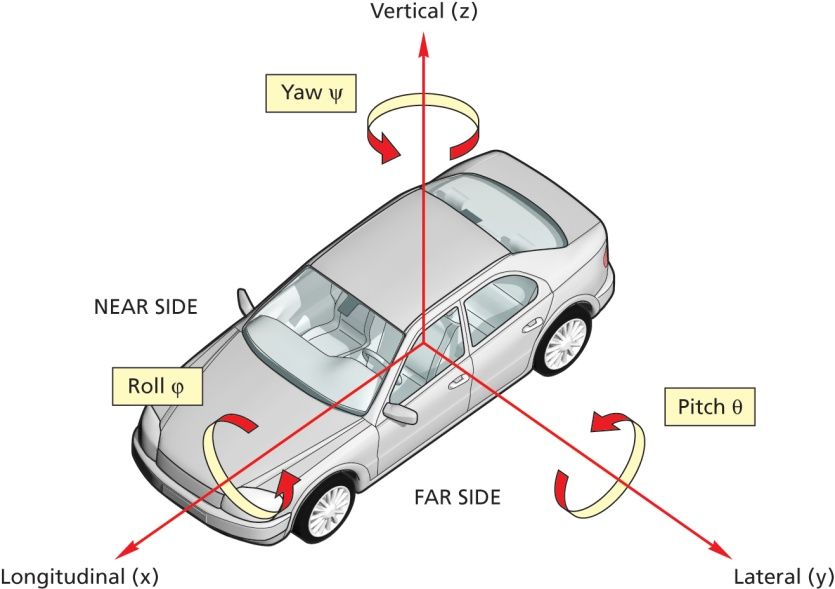
3 REFERENCE SYSTEM

3.1 Convention

3.1.1 For both VUT and GVT use the convention specified in ISO 8855:1991 in which
 the x-axis points towards the front of the vehicle, the y-axis towards the left and
 the z-axis upwards (right hand system), with the origin at the most forward point
 on the centreline of the VUT for dynamic data measurements as shown in Figure
 3-1.

3.1.2 Viewed from the origin, roll, pitch and yaw rotate clockwise around the x, y and
 z axes respectively. Longitudinal refers to the component of the measurement
 along the x-axis, lateral the component along the y-axis and vertical the
 component along the z-axis.

3.1.3 This reference system should be used for both left- and right-hand drive vehicles
 tested.

 Figure 3-1: Coordinate system and notation

 Version 3.0.2
 July 2019
 3
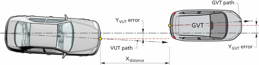
3.2 Lateral path error

3.2.1 The lateral path error is determined as the lateral distance between the centre
 of the front of the VUT and the centre of the rear of the GVT when measured in
 parallel to the intended straight-lined path as shown in the figure below.

 Lateral path error = YVUT error + YGVT error

 Figure 3-2: Lateral path error

3.3 Lateral overlap

3.3.1 The lateral overlap is defined as a percentage of the width of the VUT
 overlapping the GVT, where the reference line for the overlap definition is the
 centreline of the VUT. In case of 100% overlap, the centrelines of the VUT and
 GVT are aligned.

 Figure 3-3: Lateral Overlap examples

 Version 3.0.2
 July 2019
 4
4 MEASURING EQUIPMENT

4.1.1 Sample and record all dynamic data at a frequency of at least 100Hz.
 Synchronise using the DGPS time stamp the GVT data with that of the VUT.

4.2 Measurements and Variables

 4.2.1 Time T
 • CCRs, CCRm and CCFtap: T0 equals TTC = 4s T0
 (CCRb: T0 when GVT starts decelerating)
 • TAEB, time where AEB activates TAEB
 • TFCW, time where FCW activates TFCW
 • Timpact, time where VUT impacts GVT Timpact
 • Tsteer, time where VUT enters in curve segment Tsteer
 4.2.2 Position of the VUT during the entire test XVUT, YVUT
 4.2.3 Position of the GVT during the entire test XGVT, YGVT
 4.2.4 Speed of the VUT during the entire test VVUT
 • Vimpact, speed when VUT impacts GVT Vimpact
 • Vrel,impact, relative speed when VUT impacts GVT Vrel,impact
 4.2.5 Speed of the GVT during the entire test VGVT
 4.2.6 Yaw velocity of the VUT during the entire test ̇VUT
 4.2.7 Yaw velocity of the GVT during the entire test ̇GVT
 4.2.8 Acceleration of the VUT during the entire test AVUT
 4.2.9 Acceleration of the GVT during the entire test AGVT
 4.2.10 Steering wheel velocity of the VUT during the entire test ΩVUT

4.3 Measuring Equipment

4.3.1 Equip the VUT and GVT with data measurement and acquisition equipment to
 sample and record data with an accuracy of at least:

 • VUT and GVT speed to 0.1km/h;
 • VUT and GVT lateral and longitudinal position to 0.03m;
 • VUT heading angle to 0.1°;
 • VUT and GVT yaw rate to 0.1°/s;
 • VUT and GVT longitudinal acceleration to 0.1m/s2;
 • VUT steering wheel velocity to 1.0 °/s.

4.4 Data Filtering

4.4.1 Filter the measured data as follows:

4.4.1.1 Position and speed are not filtered and are used in their raw state.

4.4.1.2 Acceleration, yaw rate, steering wheel velocity and force are filtered with a 12-
 pole phase less Butterworth filter with a cut off frequency of 10Hz.

 Version 3.0.2
 July 2019
 5
5 GLOBAL VEHICLE TARGET

5.1 Specification

5.1.1 Conduct the tests in this protocol using the Global Vehicle Target (GVT) as
 shown in Figure 5-1 below. The GVT replicates the visual, radar and LIDAR
 attributes of a typical M1 passenger vehicle.

 Figure 5-1: Global Vehicle Target (GVT)

5.1.2 To ensure repeatable results the combination of the propulsion system and GVT
 must meet the requirements as detailed in Euro NCAP TB025 - Global Vehicle
 Target specification for Euro NCAP v1.0.

5.1.3 The GVT is designed to work with the following types of sensors:

 • Radar (24 and 77 GHz)

 • LIDAR

 • Camera

When a manufacturer believes that the GVT is not suitable for another type of sensor
system used by the VUT but not listed above, the manufacturer is asked to contact the
ANCAP Secretariat.

 Version 3.0.2
 July 2019
 6
6 MANUFACTURER DATA

6.1 Manufacturer Supplied Data

6.1.1 The vehicle manufacturer is required to provide the ANCAP Secretariat with
 colour data (expected impact speeds are not required) detailing the
 performance of the vehicle in the CCRs and CCRm scenarios for all overlap and
 impact speed combinations. The prediction is to be done for both AEB and FCW
 system tests where applicable.

6.1.2 All data must be supplied by the manufacturer before any testing begins,
 preferably with delivery of the test vehicle(s).

6.1.3 Data shall be provided for each grid point according to the following colour
 scheme for CCRs (10-50km/h for AEB and 30-80km/h for FCW) and CCRm (30-
 80km/h for both AEB and FCW):

 80 km/h
 75 km/h
 70 km/h
 65 km/h
 VUT Test Speed [km/h]

 60 km/h
 55 km/h
 50 km/h
 45 km/h
 40 km/h
 35 km/h
 30 km/h
 25 km/h
 20 km/h
 15 km/h
 10 km/h

 0 10 20 30 40 50 60 70 80
 CCRs Predicted Impact Speed [km/h]

 Version 3.0.2
 July 2019
 7
80 km/h
 75 km/h
 70 km/h
 VUT Test Speed [km/h]
 65 km/h
 60 km/h
 55 km/h
 50 km/h
 45 km/h
 40 km/h
 35 km/h
 30 km/h

 0 10 20 30 40 50 60 70 80
 CCRm Predicted Relative Impact Speed [km/h]

6.2 Absence of Manufacturer Data

6.2.1 Where predicted data is NOT provided by the vehicle manufacturer, ALL grid
 points are to be tested by the ANCAP laboratory, taking into account symmetry.

6.2.2 A system can consist of a combined AEB and FCW function or separate AEB
 or FCW functions. For combined systems, both sections 6.2.2.1 and 6.2.2.2
 apply. Where the functions are separate, section 6.2.2.1 applies to the AEB
 function and 6.2.2.2 applies to the FCW.

6.2.2.1 For AEB CCR systems tests, when there is complete avoidance, the
 subsequent test speed for the next test is incremented with 10km/h. When
 there is contact, first perform a test at a test speed 5km/h less than the test
 speed where contact occurred. After this test continue to perform the
 remainder of the tests with speed increments of 5km/h by repeating section
 8.3.1 to 8.4.3. Stop testing when the speed reduction seen in the test is less
 than 5 km/h.

6.2.2.2 For FCW system tests, when there is complete avoidance, the subsequent test
 speed for the next test is incremented by 10km/h. When there is contact, first
 perform a test at a test speed 5km/h less than the test speed where contact
 occurred. After this test continue to perform the remainder of the tests with
 speed increments of 5km/h by repeating section 8.3.1 to 8.4.3. In the AEB
 CCRm and CCRb scenarios, only perform tests at the test speeds where there
 was no avoidance in the AEB function tests, where applicable. Stop testing
 when the speed reduction seen in the test is less than 5 km/h or the relative
 impact speed is more than 50 km/h.

 Version 3.0.2
 July 2019
 8
7 TEST CONDITIONS

7.1 Test Track

7.1.1 Conduct tests on a dry (no visible moisture on the surface), uniform, solid-paved
 surface with a consistent slope between level and 1%. The test surface shall
 have a minimal peak braking coefficient (PBC) of 0.9.

7.1.2 The surface must be paved and may not contain irregularities (e.g. large dips or
 cracks, manhole covers or reflective studs) that may give rise to abnormal
 sensor measurements within a lateral distance of 3.0m to either side of the test
 path and with a longitudinal distance of 30m ahead of the VUT when the test
 ends.

7.1.3 The presence of lane markings is allowed for CCR tests. However, testing may
 only be conducted in an area where typical road markings depicting a driving
 lane may not be parallel to the test path within 3.0m either side. Lines or
 markings may cross the test path, but may not be present in the area where
 AEB activation and/or braking after FCW is expected.

7.1.4 Junction and Lane Markings

7.1.4.1 The CCFtap tests described in this document requires the use of a junction.
 The main approach lane where the VUT and GVT paths start, (horizontal lanes
 in Figure 7-1) will have a width of 3.5m. The side lane (vertical lanes in Figure
 7-1) will have a width of 3.25 to 3.5m. The lane markings on these lanes need
 to conform to one of the lane markings as defined in UNECE Regulation 130:

 1. Dashed line starting at the same point where the radius transitions into
 a straight line with a width between 0.10 and 0.15m

 2. Solid line with a width between 0.10 and 0.25m

 3. Junction without any central markings

 Figure 7-1: Layout of junction and the connecting lanes

 Version 3.0.2
 July 2019
 9
7.2 Weather Conditions

7.2.1 Conduct tests in dry conditions with ambient temperature above 5°C and below
 40°C.

7.2.2 No precipitation shall be falling and horizontal visibility at ground level shall be
 greater than 1km. Wind speeds shall be below 10m/s to minimise GVT and VUT
 disturbance.

7.2.3 Natural ambient illumination must be homogenous in the test area and in excess
 of 2000 lux for daylight testing with no strong shadows cast across the test area
 other than those caused by the VUT or GVT. Ensure testing is not performed
 driving towards, or away from the sun when there is direct sunlight.

7.2.4 Measure and record the following parameters preferably at the commencement
 of every single test or at least every 30 minutes:

 a) Ambient temperature in °C;

 b) Track Temperature in °C;

 c) Wind speed and direction in m/s;

 d) Ambient illumination in Lux.

7.3 Surroundings

7.3.1 Conduct testing such that there are no other vehicles, highway furniture,
 obstructions, other objects or persons protruding above the test surface that
 may give rise to abnormal sensor measurements within a lateral distance of
 3.0m to either side of the test path and within a longitudinal distance of 30m
 ahead of the VUT when the test ends (Figure 7-2).

7.3.2 Test areas where the VUT needs to pass under overhead signs, bridges,
 gantries or other significant structures are not permitted. For the entire test, 3m
 of free surroundings is to be ensured on both sides of the test path of the VUT.

 Figure 7-2: Free surroundings

 Version 3.0.2
 July 2019
 10
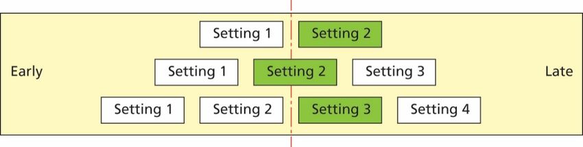
7.3.3 The general view ahead and to either side of the test area shall comprise of a
 wholly plain man made or natural environment (e.g. further test surface, plain
 coloured fencing or hoardings, natural vegetation or sky etc.) and must not
 comprise any highly reflective surfaces or contain any vehicle-like silhouettes
 that may give rise to abnormal sensor measurements.

7.4 VUT Preparation

7.4.1 AEB and FCW System Settings

7.4.1.1 Set any driver configurable elements of the AEB and/or FCW system (e.g. the
 timing of the collision warning or the braking application if present) to the
 middle setting or midpoint and then next latest setting similar to the examples
 shown in Figure 7-3.

 Figure 7-3: AEB and/or FCW system setting for testing

7.4.2 Deployable Pedestrian/VRU Protection Systems

 When the vehicle is equipped with a deployable pedestrian/VRU protection
 system, this system shall be deactivated before the testing commences.

7.4.3 Tyres

 Perform the testing with new original fitment tyres of the make, model, size,
 speed and load rating as specified by the vehicle manufacturer. It is permitted
 to change the tyres which are supplied by the manufacturer or acquired at an
 official dealer representing the manufacturer if those tyres are identical make,
 model, size, speed and load rating to the original fitment. Inflate the tyres to the
 vehicle manufacturer's recommended cold tyre inflation pressure(s). Use
 inflation pressures corresponding to least loading normal condition.

 Run-in tyres according to the tyre conditioning procedure specified in 8.1.3. After
 running-in maintain the run-in tyres in the same position on the vehicle for the
 duration of the testing.

7.4.4 Wheel Alignment Measurement

 The vehicle should be subject to a vehicle (in-line) geometry check to record the
 wheel alignment set by the OEM. This should be done with the vehicle in kerb
 weight.

7.4.5 Unladen Kerb Mass

7.4.5.1 Fill up the tank with fuel to at least 90% of the tank’s capacity of fuel.

 Version 3.0.2
 July 2019
 11
7.4.5.2 Check the oil level and top up to its maximum level if necessary. Similarly, top
 up the levels of all other fluids to their maximum levels if necessary.

7.4.5.3 Ensure that the vehicle has its spare wheel on board, if fitted, along with any
 tools supplied with the vehicle. Nothing else should be in the car.

7.4.5.4 Ensure that all tyres are inflated according to the manufacturer’s instructions
 for the appropriate loading condition.

7.4.5.5 Measure the front and rear axle masses and determine the total mass of the
 vehicle. The total mass is the ‘unladen kerb mass’ of the vehicle. Record this
 mass in the test details.

7.4.5.6 Calculate the required ballast mass, by subtracting the mass of the test driver
 and test equipment from the required 200 kg interior load.

7.4.6 Vehicle Preparation

7.4.6.1 Fit the on-board test equipment and instrumentation in the vehicle. Also fit any
 associated cables, cabling boxes and power sources.

7.4.6.2 Place weights with a mass of the ballast mass. Any items added should be
 securely attached to the car.

7.4.6.3 With the driver in the vehicle, weigh the front and rear axle loads of the vehicle.

7.4.6.4 Compare these loads with the “unladen kerb mass”

7.4.6.5 The total vehicle mass shall be within ±1% of the sum of the unladen kerb
 mass, plus 200kg. The front/rear axle load distribution needs to be within 5%
 of the front/rear axle load distribution of the original unladen kerb mass plus
 full fuel load. If the vehicle differs from the requirements given in this
 paragraph, items may be removed or added to the vehicle which has no
 influence on its performance. Any items added to increase the vehicle mass
 should be securely attached to the car.

7.4.6.6 Repeat paragraphs 7.4.6.3 and 7.4.6.4 until the front and rear axle loads and
 the total vehicle mass are within the limits set in paragraph 7.4.6.5. Care needs
 to be taken when adding or removing weight in order to approximate the
 original vehicle inertial properties as close as possible. Record the final axle
 loads in the test details. Record the axle weights of the VUT in the ‘as tested’
 condition.

 Version 3.0.2
 July 2019
 12
8 TEST PROCEDURE

8.1 VUT Pre-test Conditioning

8.1.1 General

8.1.1.1 A new car is used as delivered to the test laboratory.

8.1.1.2 If requested by the vehicle manufacturer, drive a maximum of 100km on a
 mixture of urban and rural roads with other traffic and roadside furniture to
 ‘calibrate’ the sensor system. Avoid harsh acceleration and braking.

8.1.2 Brakes

8.1.2.1 Condition the vehicle’s brakes in the following manner, if it has not been done
 before or in case the lab has not performed a 100km of driving:

 • Perform twenty stops from a speed of 56km/h with an average
 deceleration of approximately 0.5 to 0.6g.

 • Immediately following the series of 56km/h stops, perform three
 additional stops from a speed of 72km/h, each time applying sufficient
 force to the pedal to operate the vehicle’s antilock braking system (ABS)
 for the majority of each stop.

 • Immediately following the series of 72km/h stops, drive the vehicle at a
 speed of approximately 72km/h for five minutes to cool the brakes.

8.1.3 Tyres

8.1.3.1 Condition the vehicle’s tyres in the following manner to remove the mould
 sheen, if this has not been done before for another test or in case the lab has
 not performed a 100km of driving:

 • Drive around a circle of 30m in diameter at a speed sufficient to
 generate a lateral acceleration of approximately 0.5 to 0.6g for three
 clockwise laps followed by three anticlockwise laps.

 • Immediately following the circular driving, drive four passes at
 56km/h, performing ten cycles of a sinusoidal steering input in each
 pass at a frequency of 1Hz and amplitude sufficient to generate a
 peak lateral acceleration of approximately 0.5 to 0.6g.

 • Make the steering wheel amplitude of the final cycle of the final pass
 double that of the previous inputs.

8.1.3.2 In case of instability in the sinusoidal driving, reduce the amplitude of the
 steering input to an appropriately safe level and continue the four passes.

 Version 3.0.2
 July 2019
 13
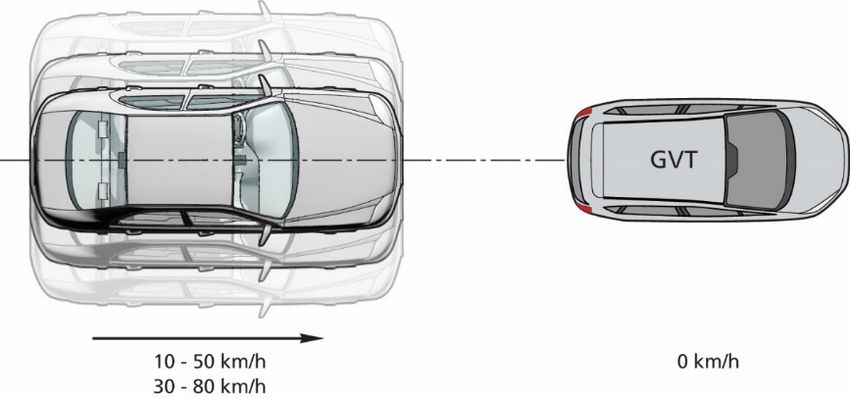
8.1.4 AEB/FCW System Check

8.1.4.1 Before any testing begins, perform a maximum of ten runs at the lowest test
 speed the system is supposed to work, to ensure proper functioning of the
 system.

8.2 Test Scenarios

8.2.1 The performance of the AEB system is assessed in the CCRs, CCRm, CCRb
 and CCFtap scenarios as shown in the sections 8.2.3, 8.2.4, 8.2.5 and 8.2.6.

 For AEB CCR, the assessment is based on a GRID prediction provided by the
 OEM. The actual scenarios to be tested to verify the prediction will be chosen
 randomly, distributed in line with the predicted colour distribution (excluding red
 points).

 The vehicle sponsor will fund 20 verification tests, where applicable. For AEB
 10 tests (CCRs and CCRm) and 10 tests for FCW (CCRs and CCRm).

 The vehicle manufacturer has the option of sponsoring up to 10 additional
 verification tests for AEB CCR and 10 for FCW.

8.2.2 For testing purposes, assume a straight-line path equivalent to the centreline of
 the lane in which the collision occurred, hereby known as the test path. Control
 the VUT with driver inputs or using alternative control systems that can modulate
 the vehicle controls as necessary to perform the tests.

8.2.3 Car-to-Car Rear stationary

 The CCRs scenario is a combination of speed and overlap with 5km/h
 incremental steps in speed and 25% in overlap within the ranges as shown in
 the tables below.

 Figure 8-1: CCRs scenario

 AEB + FCW combined
 AEB only FCW only
 AEB FCW
 10-50 km/h 30-80 km/h 10-80 km/h 30-80 km/h
 AEB CCRs
 -50%-50% -50%-50% -50%-50% -50%-50%

 ESS tests will only be allowed for the -50% overlap situation (in case of
 LHD).

 Version 3.0.2
 July 2019
 14
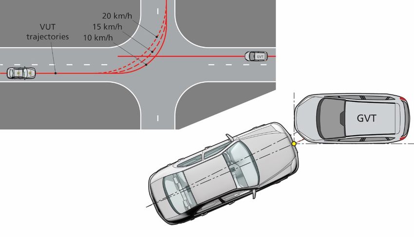
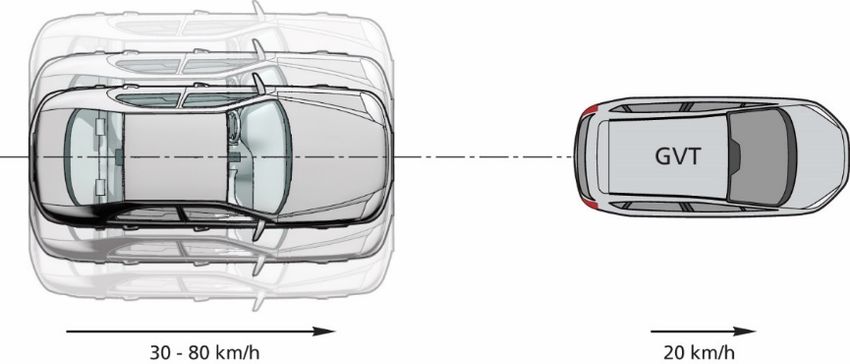
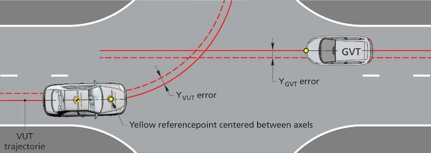
8.2.4 Car-to-Car Rear moving

 The CCRm scenario is a combination of speed and overlap with 5km/h
 incremental steps in speed and 25% in overlap within the ranges as shown
 in the tables below.

 Figure 8-2: CCRm scenario

 AEB + FCW combined
 AEB only FCW only
 AEB FCW
 30-80 km/h 50-80 km/h 30-80 km/h 50-80 km/h
 AEB CCRm
 -50%-50% -50%-50% -50%-50% -50%-50%

8.2.5 Car-to-Car Rear braking

 The CCRb tests will be performed at a fixed speed of 50km/h for both VUT
 and GVT with all combinations of -2 and -6m/s2 acceleration and 12 and
 40m headway. Different overlap situations may be tested for monitoring
 purpose at the end of the test program.

 Figure 8-3: CCRb scenario

 AEB+FCW combined, AEB only & FCW only
 -2 m/s2 -6 m/s2
 12m 50 km/h 50 km/h
 AEB CCRb
 40m 50 km/h 50 km/h

 The desired deceleration of the GVT shall be reached within 1.0 seconds
 (T0 + 1.0s) which after the GVT shall remain within ± 0.5 km/h of the
 reference speed profile, derived from the desired deceleration, until the
 vehicle speed equals 1 km/h.

8.2.6 Car-to-Car Front turn-across-path

8.2.6.1 For the CCFtap scenario, for the VUT assume an initial straight-line path

 Version 3.0.2
 July 2019
 15
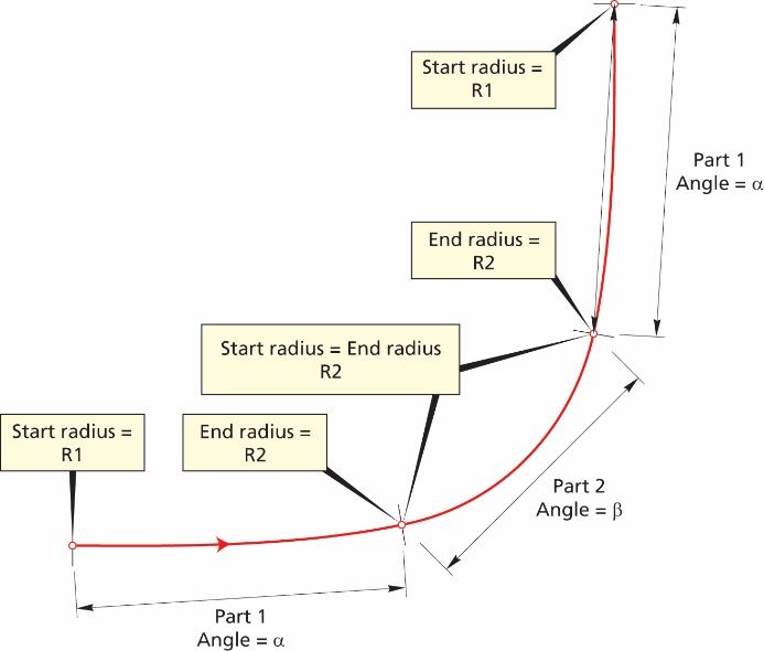
followed by a turn (clothoid, fixed radius and clothoid as specified in
 section8.2.6.5), followed again by a straight line, hereby known as the test
 path.

8.2.6.2 The GVT will follow a straight-line path in the lane adjacent to the VUT’s initial
 position, in the opposite direction to the VUT. The straight-line path of the VUT
 and GVT will be 1.75m from the centre of the centre dashed lane marking of
 the VUT lane.

 Figure 8-4: CCFtap scenario VUT and GVT paths

8.2.6.3 The paths of the VUT and target vehicle will be synchronised so that the front
 edges of the vehicle meet with a lateral position that gives a 50% overlap
 (assuming no system reaction) of the width of the VUT.

 Figure 8-5: CCFtap scenario paths and impact definition

8.2.6.4 The CCFtap scenarios are all combinations of VUT speeds of 10, 15 and 20
 km/h combined with GVT speeds of 30, 45 and 55 km/h.

8.2.6.5 The following parameters should be used to create the test paths where the
 turn signal is applied at 1.0s before Tsteer:

 Version 3.0.2
 July 2019
 16
Figure 8-6: CCFtap scenario paths definition

8.3 Test Conduct

8.3.1 Before every test run, drive the VUT around a circle of maximum diameter 30m
 at a speed less than 10km/h for one clockwise lap followed by one anticlockwise
 lap, and then manoeuvre the VUT into position on the test path. If requested by
 the OEM a simple initialisation run may be included before every test run. Bring
 the VUT to a halt and push the brake pedal through the full extent of travel and
 release.

8.3.2 For vehicles with an automatic transmission select D. For vehicles with a manual
 transmission select the highest gear where the RPM will be at least 1500 at the
 test speed. If fitted, a speed limiting device or cruise control may be used to
 maintain the VUT speed (not ACC), unless the vehicle manufacturer shows that
 there are interferences of these devices with the AEB system in the VUT. Apply
 only minor steering inputs as necessary to maintain the VUT tracking along the
 test path.

8.3.3 Perform the first test a minimum of 90s and a maximum of 10 minutes after
 completing the tyre conditioning (if applicable), and subsequent tests after the
 same time period. If the time between consecutive tests exceeds 10 minutes
 perform three brake stops from 72 km/h at approximately 0.3g.

 Between tests, manoeuvre the VUT at a maximum speed of 50km/h and avoid
 riding the brake pedal and harsh acceleration, braking or turning unless strictly

 Version 3.0.2
 July 2019
 17
necessary to maintain a safe testing environment.

8.4 Test Execution

8.4.1 Accelerate the VUT and GVT (if applicable) to the respective test speeds.

8.4.2 The test shall start at T0 (4s TTC) and is valid when all boundary conditions are
 met between T0 and TAEB and/or TFCW, or any other system intervention:

 - Speed of VUT (GPS-speed) Test speed + 1.0 km/h
 - Speed of GVT (GPS-speed) Test speed ± 1.0 km/h
 - Lateral deviation from test path for VUT
 § CCR 0 ± 0.05 m
 § CCFtap (initial straight-line path) 0 ± 0.05 m
 (turn) 0 ± [0.10] m
 - Lateral deviation from test path for GVT 0 ± [0.10] m
 - Relative distance VUT and GVT (CCRb) 12m or 40m ± 0.5m
 - Yaw velocity of VUT (CCR) 0 ± 1.0 °/s
 - Yaw velocity of GVT 0 ± [1.0] °/s
 - Steering wheel velocity 0 ± 15.0 °/s

8.4.3 The end of a test is considered when one of the following occurs:

 - VVUT = 0km/h
 - VVUT < VGVT for CCR
 - Contact between VUT and GVT

8.4.4 To avoid contact in the CCFtap scenario, the test laboratory may include an
 automated braking action by the robot in case the AEB system fails to intervene
 (sufficiently). This braking action is applied automatically when:

 - The VUT reaches the latest position at which maximum braking applied to
 the vehicle will prevent the VUT entering the path of the vehicle and no
 intervention from the AEB system is detected.
 - Lateral separation between the VUT and GVT reaches ≤ 0 during / after AEB
 intervention.

 It is at the labs discretion to select and use one of the options above to ensure
 a safe testing environment.

8.4.5 For manual or automatic accelerator control, it needs to be assured that during
 automatic brake the accelerator pedal does not result in an override of the
 system.

8.4.6 The FCW system tests should be performed using a braking robot reacting to
 the warning with a delay time of 1.2 seconds as per A.4 to account for driver
 reaction time.

8.4.7 Braking will be applied that results in a maximum brake level of -4 m/s2 - 0.50
 m/s2 when applied in a non-threat situation. The particular brake profile to be

 Version 3.0.2
 July 2019
 18
applied (pedal application rate applied in 200ms (max. 400mm/s) and pedal
 force) shall be specified by the manufacturer. When the brake profile provided
 by the manufacturer results in a higher brake level than allowed, the iteration
 steps as described in ANNEX A will be applied to scale the brake level to -4
 m/s2 - 0.50 m/s2.

8.4.8 When no brake profile is provided, the default brake profile as described in
 ANNEX A will be applied.

8.4.9 ESS evaluation will be performed as described in ANNEX B.

 Version 3.0.2
 July 2019
 19
ANNEX A BRAKE APPLICATION PROCEDURE

 The braking input characterisation test determines the brake pedal
 displacement and force necessary to achieve a vehicle deceleration typical
 of that produced by a typical real-world driver in emergency situations.

A.1 Definitions

 TBRAKE - The point in time where the brake pedal displacement exceeds
 5mm.

 T-6m/s2 - The point in time is defined as the first data point where filtered,
 zeroed and corrected longitudinal acceleration data is less than -6m/s2.

 T-2m/s², T-4m/s² - similar to T-6m/s².

A.2 Measurements

 Measurements and filters to be applied as described in Chapter 4 of this
 protocol.

A.3 Brake Characterization Procedure

 First perform the brake and tyre conditioning tests as described in 8.1.2 and
 8.1.3. The brake input characterisation tests shall be undertaken within 10
 minutes after conditioning the brakes and tyres.

A.3.1 Brake Displacement Characterisation Tests
 • Push the brake pedal through the full extent of travel and release.
 • Accelerate the VUT to a speed in excess of 85km/h. Vehicles with an
 automatic transmission will be driven in D. For vehicles with a manual
 transmission select the highest gear where the RPM will be at least 1500
 at the 85km/h.
 • Release the accelerator and allow the vehicle to coast. At a speed of
 80 ± 1.0km/h initiate a ramp braking input with a pedal application rate of
 20 ± 5mm/s and apply the brake until a longitudinal acceleration of -7m/s2
 is achieved. For manual transmission vehicles, press the clutch as soon
 as the RPM drops below 1500. The test ends when a longitudinal
 acceleration of -7m/s2 is achieved.
 • Measure the pedal displacement and applied force normal to the
 direction of travel of the initial stroke of the brake pedal, or as close as
 possible to normal as can be repeatedly achieved.

A.3.1.1 Perform three consecutive test runs. A minimum time of 90 seconds and a
 maximum time of 10 minutes shall be allowed between consecutive tests. If
 the maximum time of 10 minutes is exceeded, perform three brake stops
 from 72 km/h at approximately 0.3g.

 • Using second order curve fit and the least squares method between
 T-2m/s², T-6m/s², calculate the pedal travel value corresponding to a
 longitudinal acceleration of -4 m/s² (=D4, unit is m). Use data of at least

 Version 3.0.2
 July 2019
 20
three valid test runs for the curve fitting.
 • This brake pedal displacement is referred to as D4 in the next chapters.
 • Using second order curve fit and the least squares method between T-
 2m/s², T-6m/s², calculate the pedal force value corresponding to a
 longitudinal acceleration of -4 m/s² (=F4, unit is N). Use data of at least
 three valid test runs for the curve fitting.
 • This brake pedal force is referred to as F4 in the next chapters.

A.3.2 Brake Force Confirmation and Iteration Procedure
 • Accelerate the VUT to a speed of 80+1km/h. Vehicles with an automatic
 transmission will be driven in D. For vehicles with a manual transmission
 select the highest gear where the RPM will be at least 1500 at the
 80km/h.
 • Apply the brake force profile as specified in B.4, triggering the input
 manually rather than in response to the FCW. Determine the mean
 acceleration achieved during the window from TBRAKE +1s TBRAKE +3s. If
 a mean acceleration outside the range of -4-0.5m/s2 results, apply the
 following method to ratio the pedal force applied.
 F4new = F4original * (-4/mean acceleration), i.e. if F4original results in a
 mean acceleration of -5m/s2, F4new = F4original * -4 / -5
 • Repeat the brake force profile with this newly calculated F4, determine
 the mean acceleration achieved and repeat the method as necessary
 until a mean acceleration within the range of -4-0.5m/s2 is achieved.

A.3.2.1 Three valid pedal force characteristic tests (with the acceleration level being
 in the range as specified) are required. A minimum time of 90 seconds and
 a maximum time of 10 minutes shall be allowed between consecutive tests.
 If the maximum time of 10 minutes is exceeded, perform three brake stops
 from 72 km/h at approximately 0.3g.

 • before restarting the brake pedal force characterisation tests. This brake
 pedal force is referred as F4 in the next chapters.

A.4 Brake Application Profile
 • Detect TFCW during the experiment in real-time.
 • Release the accelerator at TFCW + 1 s.
 • Perform displacement control for the brake pedal, starting at TFCW + 1.2
 s with a gradient of the lesser of 5 x D4 or 400mm/s (meaning the gradient
 to reach pedal position D4 within 200ms, but capped to a maximum
 application rate of 400mm/s).
 • Monitor brake force during displacement control and use second-order
 filtering with a cut-off frequency between 20 and 100 Hz (online) as
 appropriate.
 • Switch to force control, maintaining the force level, with a desired value
 of F4 when

 Version 3.0.2
 July 2019
 21
i. the value D4 as defined in B.3 is exceeded for the first time,

 ii. the force F4 as defined in B.3 is exceeded for the first time,

 whichever is reached first.

 • The point in time where position control is switched to force control is
 noted as Tswitch.
 • Maintain the force within boundaries of F4 ± 25% F4. A stable force level
 should be achieved within a period of 200ms maximum after the start of
 force control. Additional disturbances of the force over ± 25% F4 due to
 further AEB interventions are allowed, as long as they have a duration of
 less than 200ms.
 • The average value of the force between TFCW + 1.4s and the end of the
 test should be in the range of F4 ± 10 N.

Version 3.0.2
July 2019
 22
ANNEX B Emergency Steering Support

The ESS is evaluated at the ANCAP lab with input from the OEM to ensure proper
triggering of the system.

 Version 3.0.2
 July 2019
 23
You can also read