D2.5 MICRO-SIMULATION GUIDE FOR AUTOMATED VEHICLES - COEXIST
←
→
Page content transcription
If your browser does not render page correctly, please read the page content below
D2.5
 Micro-simulation guide for
 automated vehicles

 Version: 1.0
 Date: 31.10.18
 Author: Peter Sukennik (PTV Group)

The sole responsibility for the content of this document lies with the authors. It does not
necessarily reflect the opinion of the European Union. Neither the EASME nor the European
Commission are responsible for any use that may be made of the information contained therein.

                    This project has received funding from the European Union’s Horizon 2020
                    research and innovation programme under grant agreement No. 723201-2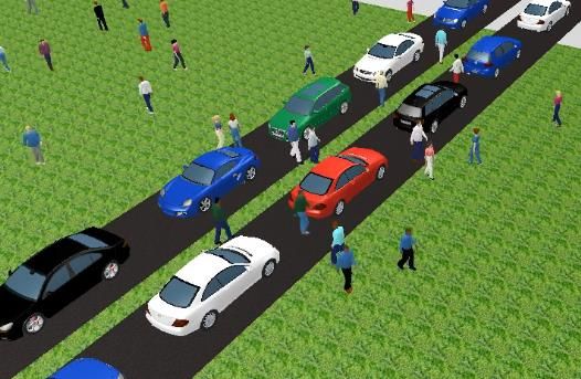
Document Control Page
Title                                          Micro-simulation guide for automated vehicles

Creator                                        Peter Sukennik (PTV Group)

Editor                                         Charlotte Fléchon (PTV Group)

                                               Bernard Gyergyay (Rupprecht)
                                               Johan Olstam (VTI)
Reviewer
                                               Charlotte Fléchon (PTV Group)
                                               Jared Best (PTV Group)

Brief Description

Contributors
Type
                                               D2.5
(Deliverable/Milestone)
Format

Creation date

Version number                                 1.0

Version date                                   31/10/2018

Last modified by
Rights

Audience
                                                     Internal
                                                     Public
                                                     Restricted, access granted to: EU Commission
Action requested
                                                  To be revised by Partners involved in the preparation of the
                                               Deliverable
                                                     For approval of the WP Manager
                                                     For approval of the Internal Reviewer (if required)
                                                     For approval of the Project Co-ordinator

Deadline for approval
Versi
                  Date                                   Modified by                  Comments
on

          This project has received funding from the European Union’s Horizon 2020                   h2020-coexist.eu Page 2 of 29
          research and innovation programme under grant agreement No. 723201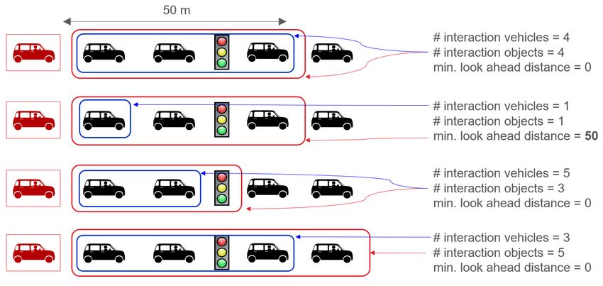
This project has received funding from the European Union’s Horizon 2020   h2020-coexist.eu Page 3 of 29
research and innovation programme under grant agreement No. 723201

Table of contents
1      Purpose of this document ......................................................................... 6
1.1 What is possible in PTV Vissim? ....................................................................................... 6
1.2 Communication and cooperation ....................................................................................... 6
1.3 The CoEXist project ........................................................................................................... 7
2      AV characteristics & assumptions ........................................................... 7
2.1 Field data ........................................................................................................................... 8
2.2 AV Driving logic ................................................................................................................. 8
2.3 Reduction of stochastics .................................................................................................... 9
    2.3.1    Functions ................................................................................................................................9
    2.3.2    Distributions..........................................................................................................................10
3      Simulation with PTV Vissim internally.................................................... 11
3.1 Driving behaviour settings on a link level ......................................................................... 11
    3.1.1    Driving behaviour..................................................................................................................11
    3.1.2    Link behaviour types.............................................................................................................12
    3.1.3    Spatial extent........................................................................................................................12
3.2 AV related features .......................................................................................................... 13
    3.2.1    Enforce absolute braking distance ........................................................................................14
    3.2.2    Use implicit stochastics ........................................................................................................15
    3.2.3    Number of interaction objects and vehicles ..........................................................................16
    3.2.4    Headway based on leader vehicle class ...............................................................................17
    3.2.5    Increased acceleration .........................................................................................................18
    3.2.6    Occupancy distribution with zero passengers .......................................................................19
    3.2.7    Consider vehicles in dynamic potential .................................................................................20
    3.2.8    Platooning ............................................................................................................................20
3.3 Driving parameters .......................................................................................................... 21
    3.3.1    Following behaviour..............................................................................................................21
    3.3.2    Lane change behaviour ........................................................................................................22
    3.3.3    Lateral behaviour ..................................................................................................................22
    3.3.4    Signal control behaviour .......................................................................................................23
3.4    AV – Penetration rates .................................................................................................... 23
3.5    Future adaptation of human drivers ................................................................................. 23
3.6    Safety aspects ................................................................................................................. 23
3.7    Examples ......................................................................................................................... 24
4      Simulation with PTV Vissim externally ................................................... 24

             This project has received funding from the European Union’s Horizon 2020                             h2020-coexist.eu Page 4 of 29
             research and innovation programme under grant agreement No. 723201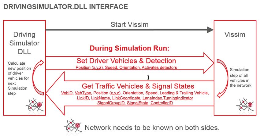
4.1 PTV Vissim interfaces ..................................................................................................... 25
    4.1.1   COM .....................................................................................................................................25
    4.1.2   DriverModel ..........................................................................................................................26
    4.1.3   DrivingSimulator ...................................................................................................................27
4.2 Vehicles Dynamics & sensors (nano-simulation) ............................................................. 29
5      Next steps ................................................................................................. 29

            This project has received funding from the European Union’s Horizon 2020                             h2020-coexist.eu Page 5 of 29
            research and innovation programme under grant agreement No. 723201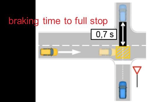
1 Purpose of this document
This document was created as part of the project CoEXist1. The intent of this document is to provide
a comprehensive description on modelling of automated vehicles with PTV Vissim 11 or later
versions. Adjustments to different types of models, in simulation software other than PTV Vissim,
can be inferred from the recommendations given here, but caution must be taken especially when
the driving behaviour parameters are based on a different type of model (e.g. models apart from
Wiedemann).

1.1 What is possible in PTV Vissim?
Automated vehicles can have different automation levels2, different automation functions, different
sensor equipment, and different driving logics. The modelling technique depends on the scope of
information you have about the automated vehicles.

With driving logics algorithms
If the driving logics algorithms are known or under development, one of PTV Vissim’s interfaces can
be used to couple the algorithms with PTV Vissim. This allows direct testing of algorithms, giving the
ability to visualize and compare the interaction between automated vehicles equipped with the
algorithms and conventional vehicles provided by the PTV Vissim model. This process is described
in ‘D2.2 Technical Report on connecting AV control logic and AC Simulator’ available on the CoEXist
website.

Without driving logics algorithms
If the algorithms are not known, the driving behaviours offered by PTV Vissim can be used as a
starting point for the model. The expected driving behaviour of automated vehicles should be always
considered. Saying e.g. automation level 4 is insufficient for microscopic simulation because it
requires knowledge or assumptions about the behaviour when following lane changing, reacting on
signals or resolving conflicts, e.g. gaps, thresholds, etc. Using the human driver as a benchmark,
expected behaviour of automated vehicles in terms of desired speed or acceleration can be defined
(following headway, its variability, etc.). Some suggestions are provided by in 2 AV characteristics &
assumptions for more information.

1.2 Communication and cooperation

Basic cooperation features are implemented in PTV Vissim already. However, these have been
introduced to replicate how humans cooperate. Cooperation beyond that scope needs to be reflected
another way.

1See https://www.h2020-coexist.eu/
2See SAE Taxonomy and Definitions for Terms Related to Driving Automation Systems for On-Road Motor
Vehicles (J3016) https://www.sae.org/standards/

          This project has received funding from the European Union’s Horizon 2020   h2020-coexist.eu Page 6 of 29
          research and innovation programme under grant agreement No. 723201
Figure 1 Driving behaviour window from Vissim 11, where advanced merging and the parameters for cooperative
lane change are highlighted
Communication and cooperation might be a complex process with complex or simple outputs and
impacts. For example, if the impact of communication between vehicles leads to small headways
between them, you might achieve this by changing the driving behaviour parameters, especially
CC0, CC1, CC2, CC6. See general PTV Vissim help for parameter description - Defining the
Wiedemann 99 model parameters.
If the communication leads to complex longitudinal and lateral maneuverers, then you would likely
need to use one of the PTV Vissim interfaces and describe the manoeuvres as an algorithm.
Communication in vehicle platoons including joining or leaving the platoon will be provided as feature
in future service pack of PTV Vissim. See section 3.2.8 Platooning for more information.
1.3 The CoEXist project
Many AV-related enhancements and new features in PTV Vissim have been implemented within the
project CoEXist. CoEXist is a European project (May 2017 – April 2020) which aims at preparing the
transition phase during which automated and conventional vehicles will coexist on cities’ roads. For
more information see https://www.h2020-coexist.eu/.
2 AV characteristics & assumptions
This project has received funding from the European Union’s Horizon 2020 h2020-coexist.eu Page 7 of 29
research and innovation programme under grant agreement No. 7232012.1 Field data
Field data from the test track in Helmond (NL) collected as part of CoEXist3 has shown for tested
automated vehicles:
• Almost a linear relationship between headway and speed when following a manually driven
car or an automated car without car-to-car (C2C) communication.
• A linear deterministic relationship between headway and speed when following another
automated vehicle with car-to-car (C2C) communication.
• Oscillations during vehicle following are small with little variation in comparison with human
drivers.
• No stochastic variation in driveaway behaviour. That was observed when vehicle accelerated
on green signal at the intersection.
To reproduce the behaviour observed on the test track, it is necessary to change the driving
behaviour parameters based on Wiedemann 99 model and use additional features developed for
this purpose. See section 3.2 AV related features for more information.
2.2 AV Driving logic
Each automated vehicle uses a driving logic. Instead of distinguishing between car manufacturer’s
or company’s driving logics, CoEXist works with 4 fundamental driving logics described by their major
principles and capabilities. The logics are named rail safe, cautious, normal, and all-knowing.
The driving logics cautious, normal and all-knowing are part of the PTV Vissim default.inpx file as
separate driving behaviours. They are based on the Wiedemann 99 car-following model with
adjusted driving behaviour parameters and additional features developed for PTV Vissim 11. See
section 3.2 AV related features for more information.
The rail safe driving logic is not included in PTV VISSIM DEFAULT.INPX file because of its special
nature and application area.
Rail safe
This driving logic requires the appropriate parameters in addition to a special modelling approach to
be in line with the driving logic principles. The rail safe driving logic describes a deterministic
behaviour that represents the closed, controlled environment found at ports or within factories. It is
characterized by the presence of physically separate lanes or large lateral distances, a pre-defined
path that the vehicles follow, no lane change, and no unsignalized intersection. Furthermore, the
brick wall stop distance always remains activated, see the feature enforce absolute braking
distance, section 3.2.1 3.2.1Enforce absolute braking distance. The modeller needs to keep all
these specific details in mind.
Cautious
3See “D2.6 Technical report on data collection and validation process” for additional information about the
data collection process. Report available on www.h2020-coexist.eu.
This project has received funding from the European Union’s Horizon 2020 h2020-coexist.eu Page 8 of 29
research and innovation programme under grant agreement No. 723201The vehicle observes the road code and always adopts a safe behaviour. The brick wall stop distance
is always active, see the feature enforce absolute braking distance and unsignalized intersections
and lane changes are possible, but the vehicle will maintain large gaps. See section 3.2.1 Enforce
absolute braking distance for more information.
Normal
The vehicle behaves like a human driver with the additional capacity of measuring distances and
speeds of the surrounding vehicles with its range of sensors.
All-knowing
The vehicle has profound awareness and predictive capabilities, leading mainly to smaller gaps for
all manoeuvres and situations. A kind of cooperative behaviour is expected.
2.3 Reduction of stochastics
Stochastics have been implemented into PTV Vissim to reflect the randomness of human driving
behaviour. Two types of stochastics are available in PTV Vissim:
Explicit stochastics
Is defined by functions and distributions which the user can change directly.
Implicit stochastics
Is hard-coded and cannot be changed by the user. However, starting with PTV Vissim 11, this can
be switched off (is on by default) in the dialog or list of driving behaviours (tab Following). See section
3.2.2 Use implicit stochastics for more information.
2.3.1 Functions
Functions are accessible through the main menu: Base Data > Functions.
It is expected that automated vehicles will behave deterministically instead of stochastically like
human drivers. This might have implications on the acceleration and deceleration behaviours. Based
on this assumption, the modeler can reduce the spread of values for individual vehicles for:
• Desired acceleration
• Desired deceleration
• Maximum acceleration
• Maximum deceleration
The reduction can be done by simply changing the max and min curves, bringing them closer to the
median curve or putting them on the median curve:
This project has received funding from the European Union’s Horizon 2020 h2020-coexist.eu Page 9 of 29
research and innovation programme under grant agreement No. 723201Figure 2 Example of a possible modification of the desired acceleration curve
To make this change, the modeller can use the list of correspondent function with the coupled list
Data Points and copy the Y value to yMin and yMax, multiply them by an appropriate factor, or
change them manually:
Figure 3 Illustration of how to modify the maximum acceleration function
2.3.2 Distributions
Distributions are accessible through the main menu: Base Data > Distributions.
2.3.2.1 Desired speed
The distribution function of desired speeds is a particularly important parameter since it has an
impact on link capacity and achievable travel times. The desired speed is the speed the driver wants
to drive. The real speed is a result from interaction with other drivers and objects in the simulation,
and each vehicle is assigned an individual desired speed from a distribution. With human drivers, a
large spread of desired speeds can be observed. However, automated vehicles may operate with a
much lower spread because they likely obey speed limits. Therefore, the automated vehicles might
get different desired speed distributions than the conventional vehicles.
To do so, create a new speed distribution used by automated vehicles only and set appropriate
boundaries.
This project has received funding from the European Union’s Horizon 2020 h2020-coexist.eu Page 10 of 29
research and innovation programme under grant agreement No. 723201Figure 4 Example of a modification of the desired speed distribution
2.3.2.2 Time
Time is an important distribution because it is used to define the CC1 driving parameter. The time
has impact on the capacity, see PTV Vissim Help Defining the Wiedemann 99 model parameters for
details. CC1 is a time distribution of the speed-dependent part of desired safety distance. Each time
distribution may be empirical or normal. Each vehicle has an individual, random safety variable. PTV
Vissim uses this random variable as a fractile for the selected time distribution CC1. The randomness
can be switched off by deactivating use implicit stochastic. See section 3.2.2 Use implicit
stochastics for more information.
The appropriate value(s) for the time distribution for CC1 parameter depends on the expected
behaviour of the automated vehicle. The value might be larger value for cautious vehicles or smaller
value for all-knowing vehicles in comparison with the value used for conventional vehicles by default
(0.9 s).
3 Simulation with PTV Vissim internally
3.1 Driving behaviour settings on a link level
PTV Vissim allows to define vehicle class-specific driving behaviours for each link or connector in
the network. This means different vehicles can behave differently on the same link/connector, e.g.
cars and HGVs or conventional cars and automated cars.
3.1.1 Driving behaviour
PTV Vissim offers predefined driving behaviours, which can be easily adjusted by the user. We
recommend duplicating a specific driving behaviour(s), adjusting them if necessary, and then using
it in your simulation.
This project has received funding from the European Union’s Horizon 2020 h2020-coexist.eu Page 11 of 29
research and innovation programme under grant agreement No. 723201Note: The driving behaviours for automated vehicles are not extensively
tested and compared with the real world yet because of a simple fact. There
are only few automated vehicles on the roads as of 2018 and they are
capable of only the simpler part of the driving tasks (following). Driving
parameter values proposed by PTV are based on empirical studies and co-
simulation data collected within CoEXist (following behaviour only) as well as
on several assumptions. If your assumptions differ, consider changing the
parameter values and features settings.
3.1.2 Link behaviour types
In the list of Link behavior types, you can specify which driving behaviour will be used by default
and in the coupled right-hand-side-list Driving behaviors you can specify additionally driving
behaviours for individual vehicle classes. This will allow e.g. a vehicle from vehicles class
Car_AV_cautious behave differently compared to a conventional car.
Figure 5 Example of how to set different driving behaviour to the vehicle classes
3.1.3 Spatial extent
In the real world or in a scenario, the study area might be spatially divided into several zones where
different driving logics are required. For example, there might be an AV-friendly part of the city, where
the vehicles could use normal or all-knowing driving logic, but also another part of the city where a
cautious driving logic is needed. To achieve this, you need to define link behaviour types to cover all
possible behaviours of your automated vehicle and then assign this link behaviour type to links in
the corresponding part of your model. As a result, the same vehicle can use different driving logics
in different parts of the network.
Figure 6 Example of how to set different driving behaviour for different link types
Analogically, a highly developed automated vehicle can drive with all-knowing driving behaviour
through the network but act as a rail safe or cautious vehicle in a parking garage or shared space.
Example from the CoEXist project:
This project has received funding from the European Union’s Horizon 2020 h2020-coexist.eu Page 12 of 29
research and innovation programme under grant agreement No. 723201The scenario includes 3 different AV vehicle classes, and each vehicle class uses a specific driving
logic for a specific road type (see the Table 1 below). In this case, you can define four link behaviour
types (motorway, arterial, urban street, shared space) combined with four driving behaviours
(cautious, normal, all-knowing, manual – for each of them an urban and freeway option is defined
because of differences in lane change parameters) for three AV vehicle classes (basic AV,
intermediate AV, advanced AV)4.
Table 1 Specification of which driving logic basic AVs, intermediate AVs and advanced AVs could use in
different road environments.
Road type Driving logic:
(Cautious (C), Normal (N), All-Knowing (AK), Manual (M))
Basic AV Intermediate AV Advanced AV
Motorway C N AK
Arterial C C/N AK
Urban street M C N
Shared space M M C
Figure 7 Scenario including 3 different AV vehicle classes, and each vehicle class uses a specific driving logic
for a specific road type
3.2 AV related features
Multiple additional attributes are available in the driving behaviour dialogs since PTV Vissim 11. Most
are required mainly for modelling of CAV (connected and/or automated vehicles), but many can also
be used for calibration of human behaviour. The added attributes are explained in the following
chapters.
4 For more information, please refer to deliverable 1.4 “Scenario specification for eight use cases”
This project has received funding from the European Union’s Horizon 2020 h2020-coexist.eu Page 13 of 29
research and innovation programme under grant agreement No. 723201Figure 8 The driving behaviour window with the relevant attributes highlighted in yellow
Table 2 Recommended settings for the AV-related features
3.2.1 Enforce absolute braking distance
If the attribute Enforce absolute braking distance (a.k.a. brick wall stop distance) is checked,
vehicles using this driving behaviour will always make sure that they could brake without a collision,
even if the leading vehicle comes to an immediate stop (turns into a brick wall).
This condition applies also:
• to lane changes for the vehicle itself on the new lane and for the trailing vehicle on the new
lane and
• to conflict areas for the following vehicle on the major road.
• Following:
This project has received funding from the European Union’s Horizon 2020 h2020-coexist.eu Page 14 of 29
research and innovation programme under grant agreement No. 723201Figure 9 Illustration of the definition of the following distance
• Lane change:
Figure 10 Illustration of the distances involved in the lane changing process
• Gap acceptance5 at intersections (conflict areas only):
Figure 11 Illustration of the rear gap
Activating Enforce absolute braking distance is recommended for rail safe and cautious driving
logic vehicles.
3.2.2 Use implicit stochastics
If the attribute Use implicit stochastics is unchecked (default is checked), a vehicle using this
driving behaviour does not use any internal stochastic variation that is meant to model the
imperfection of human drivers. For all distributions that cannot be explicitly set by the user, a median
value is used instead of a random value.
This affects:
• the safety distances
• the desired acceleration
• the desired deceleration
• the estimation uncertainty for braking decisions
The three former variables are partially defined by attributes/functions accessible to the user, so this
5 Rear gap = time to brake to full stop 1 m in front of the conflict area
This project has received funding from the European Union’s Horizon 2020 h2020-coexist.eu Page 15 of 29
research and innovation programme under grant agreement No. 723201part is still valid, but the additional stochastic spread included in the internal model is reduced to
zero.
Deactivating Use implicit stochastics is recommended for all automated vehicles or for that part of
the infrastructure, where the vehicle drives in automated mode.
3.2.3 Number of interaction objects and vehicles
The attribute observed vehicles from PTV Vissim 10 has been split into two attributes:
• Number of interaction objects refers to vehicles and internal objects (reduced speed areas,
stop signs, priority rules, red signal head)
• Number of interaction vehicles refers only to real vehicles
The number of interaction vehicles defines an upper limit for the observed leading vehicles,
therefore, for example, this could be set to 1 for automated vehicles with a sensor equipment that
cannot see through the leading vehicle. A red signal downstream of the leading vehicle would still
be observed, but not the second real vehicle downstream.
Examples
Number of interaction objects: 3 (first three objects are visible for the red car)
Number of interaction vehicles: 1 (only one vehicle is visible for the red car)
Objects
Vehicles
Figure 12 Example of the use of the new attributes: number of interaction objects and number of interaction
vehicles
Another situational examples:
This project has received funding from the European Union’s Horizon 2020 h2020-coexist.eu Page 16 of 29
research and innovation programme under grant agreement No. 723201Figure 13 Additional examples of the use of the new attributes: number of interaction objects and number of
interaction vehicles.
Per default, within the Wiedemann 99 model, the number of interaction objects is set to 2 and the
number of interaction vehicles is set to 99, which is the maximum possible value.
It is possible to enter a higher number of interaction vehicles than objects; however, the number of
interaction objects is always the limiting factor.
If the number of interaction vehicles is equal or higher than the number of interaction objects, you
get the same setup as in PTV Vissim 10 or earlier releases.
If you set the number of interaction vehicles lower than the number of interaction objects, you will
limit the number of visible vehicles within the visible objects.
3.2.4 Headway based on leader vehicle class
On the new tab page Car following model in the driving behavior dialog or in the coupled list
Vehicle Class Following Behavior, some of the parameter values affecting the desired safety
distance can be specified per vehicle class of the leading vehicle now, in addition to the value for all
other vehicles.
This can be used, for example, for having connected vehicles using a smaller safety distance when
following another connected vehicle but a larger safety distance when following a human driver or a
bike.
This project has received funding from the European Union’s Horizon 2020 h2020-coexist.eu Page 17 of 29
research and innovation programme under grant agreement No. 723201Figure 14 Example of different headway settings depending on the vehicles class of the leading vehicle
Figure 15 List of vehicle class following behavior where some of the parameter values affecting the desired safety
distance can be specified per vehicle class of the leading vehicle
3.2.5 Increased acceleration
This attribute is accessible through the Driving behaviors list and can be set in dependency on
leading vehicle class in the coupled list Vehicle class following.
The normal human acceleration behaviour cannot use reliable information about the future behaviour
of the leading vehicle, and therefore, normal Vissim vehicles tend to fall behind when the leading
vehicle is accelerating. But automated vehicles, especially if using car-to-car (C2C) communication,
can use a tight coupling with small headways.
If the attribute Increased acceleration is set to a higher value than 100%, a vehicle using this driving
behaviour can accelerate with the given percentage of its normal desired acceleration, but not
exceeding its maximum acceleration if the leading vehicle is faster and accelerating.
This project has received funding from the European Union’s Horizon 2020 h2020-coexist.eu Page 18 of 29
research and innovation programme under grant agreement No. 723201Figure 16 The driving behaviors / Vehicle class following behaviors list in which the increased acceleration can
be set
3.2.6 Occupancy distribution with zero passengers
For empty automated vehicles (without passengers), it is now possible to define an empirical
occupancy distribution which contains zero passengers. You can do so in the coupled list Data
points.
Figure 17 The occupancy distributions / Data points list
Figure 18 Occupancy distribution is set to zero
This project has received funding from the European Union’s Horizon 2020 h2020-coexist.eu Page 19 of 29
research and innovation programme under grant agreement No. 7232013.2.7 Consider vehicles in dynamic potential
The interaction between vehicles and pedestrians is mainly modelled as conflict areas, which do
block a certain area if a vehicle or pedestrian is within the area or approached it. In this case, others
are not allowed to use this area.
Vehicles blocking a conflict area can now be considered in the dynamic potential for conflicting
pedestrians. If this option has been activated on a pedestrian link, pedestrians will not stop at a
blocked conflict area, but will try to walk around it through the gaps between queued vehicles. For
this, the lanes of a pedestrian link need to be sufficiently narrow. For example, lane widths of 0.6 m
only, so that at least one lane conflict remains open between queued cars. Dynamic potential for
pedestrian routes needs to be active.
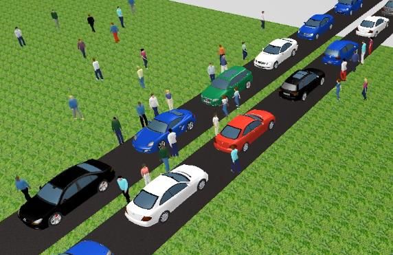
Figure 19 Left-hand side: interaction pedestrians-vehicles when dynamic potential is disactivated, the pedestrians are
waiting in front of the standing vehicles; right-hand side: interaction pedestrians-vehicles when dynamic potential is
activated, the pedestrians are actively looking for and using the gaps between the standing vehicles
Link for vehicles
Conflict area
Multilane link
used as
pedestrian area
Figure 20 Left-hand side: link dialog: activation of “consider vehicles in dynamic potential”; right-hand side network
objects needed
The parameter G for vehicles in dynamic potential affects the general strength of vehicles (default
value: 3). This attribute also influences the oncoming lane.
3.2.8 Platooning
Platooning as a parametrized feature in PTV VISISM GUI is planned to be implemented in the last
quarter of 2018 and should available for PTV Vissim users with a service pack in 2019. A script-
This project has received funding from the European Union’s Horizon 2020 h2020-coexist.eu Page 20 of 29
research and innovation programme under grant agreement No. 723201based platooning example is available already within the PTV Vissim installation.
3.3 Driving parameters
The tables in the following subchapters recommend the direction of change for the driving behaviour
parameters to model CAVs. Specific numeric values proposed within CoEXist, which can be used
as a starting setting, are available as three additional driving behaviours directly in the default
network file, so they appear in the driving behaviour list after opening PTV Vissim or creating a new
file, if you did not save your own default network file before without these new driving behaviours.
Note: The specific parameter values available within cautious, normal and all-
knowing driving behaviour are not the only possible values. The development
on the field of automated vehicles is fast and the resulting driving behaviour if
influenced by many factors like legislation, legal aspects, hardware and
software equipment, weather and visibility conditions.
3.3.1 Following behaviour
Because of deterministic behaviour of automated vehicles and to reflect much smaller oscillation in
vehicle following:
• CC2 can be reduced up to zero
• CC4 and CC5 can be significantly reduced
• CC6 can be reduced up to zero
Table 3 General recommendations for the Wiedemann following behaviours and the rail safe, cautious, normal
and all-knowing driving logics
control logic
model parameter** rail safe cautious normal all knowing
CC0 def def def smaller
CC1 def/higher* def/higher* def smaller
CC2 def/smaller def/smaller smaller smaller
Wiedemann 99
CC3 def/higher def/higher def def
following behavior
CC4 Smaller def/smaller def/smaller smaller
CC5 Smaller def/smaller def/smaller smaller
CC6 def/smaller def/smaller def smaller
CC7 def/smaller def/smaller def/smaller smaller
CC8 Smaller smaller def def
CC9 Smaller smaller def def
ax def def def smaller
W74
bxadd def/higher* def/higher* def smaller
bxmult def/higher* def/higher* def smaller
* if EABD is on, brick wall stop distance is guaranteed ** see PTV Vissim manual for detailed description
This project has received funding from the European Union’s Horizon 2020 h2020-coexist.eu Page 21 of 29
research and innovation programme under grant agreement No. 723201Note: Although the table above also contains the parameters for the
Wiedemann 74 model, it is recommended to use Wiedemann 99 to simulate
automated vehicles because of more options to control the behaviour through
the driving parameters.
3.3.2 Lane change behaviour
For the lane change behaviour, the most important parameter is the Safety distance reduction
factor, which is set to 0.6 by default in PTV Vissim. That means vehicles accept smaller gaps for
lane change as for following.
Note: For automated vehicles, this parameter might be higher or lower in
value in comparison to the default value based on the driving logic or
assumed behaviour in lane change manoeuvres. There are different default
values for urban and freeway driving behaviours. To include automated
vehicles in a model, we recommend using two driving behaviours: one for
urban roadways and another for freeway type of infrastructure.
Table 4 General recommendation for lane changing behaviours
Table 5 General recommendation for lane changing behaviour functionalities
3.3.3 Lateral behaviour
There are no suggestions regarding lateral behaviour from CoEXist. Automated vehicles will likely
try to keep the lateral position in the middle of the lane. There might be requirements for lateral
distance to other road space users, especially to vulnerable road users. These can be defined class
dependent on the tab Lateral in the driving behaviour dialog according to expected behaviour of the
automated vehicle.
This project has received funding from the European Union’s Horizon 2020 h2020-coexist.eu Page 22 of 29
research and innovation programme under grant agreement No. 7232013.3.4 Signal control behaviour
For the signal control behaviour, defining the reduced safety distance factor in an appropriate way
is important. This parameter is set to 0.6 by default. For automated vehicles, this can be set to 1 if it
is expected that they do not change the safety distances in the proximity of a signalized intersection.
On the other hand, if it is expected that automated vehicles will also reduce the safety distances in
proximity to signalized intersections, then set this value lower than 1. The proximity itself is described
by reduced safety start (end) up (down) stream of stop line.
Table 6 General recommendation for signal control behaviour
3.4 AV – Penetration rates
While testing the future scenarios with automated vehicles, different penetration rates of different
kinds of automated vehicles or driving logics are often of interest. To address this, it is possible to
simply change the vehicle composition with the corresponding share of automated vehicle types. For
example, to model 50% conventional, 30% cautious, and 20% normal, the settings should be:
Figure 21 Example of the settings for a model with the following share of driving behaviour: 50% conventional,
30% cautious, and 20% normal
3.5 Future adaptation of human drivers
With a growing share of automated vehicles in the traffic flow, the behaviour of other human drivers
might also change. Because of lack of empirical data and real experience with higher penetration
rates of automated vehicles as of 2018, specific recommendation cannot be provided, except that
this aspect should not be overseen and should be taken into account when listing the assumptions
of the model..
3.6 Safety aspects
For conventional vehicles with human drivers, the safety aspects can be investigated using the
This project has received funding from the European Union’s Horizon 2020 h2020-coexist.eu Page 23 of 29
research and innovation programme under grant agreement No. 723201SSAM model (Surrogate Safety Assessment Model6). According to the SSAM software user manual,
“it provides guidance on the installation and use of the software, which is used to perform
surrogate safety analysis of a traffic facility, such as a signalized intersection. It does so by
processing vehicle trajectory data from a given microscopic traffic simulation to identify the
frequency of conflicts-where two vehicles are on a collision course and one vehicle must make
an evasive maneuver to avoid a collision. Such surrogate measures have been shown to correlate
to some degree with the historical frequency of crashes at intersections.”
Unfortunately, due to the lack of data on the frequency of crashes at intersections with automated
vehicles, there is no experience in applying such techniques for automated vehicles and the results
should be handle with precaution. It is not clear whether the thresholds used in SSAM for defining
conflicts and severity of conflicts are also valid for automated vehicles, especially for the all-knowing
driving logic, which might be able to drive with short safety distances without being unsafe or at least
not as unsafe as a human driver would be in the same situation.
3.7 Examples
All AV-related examples are available in …\EXAMPLES TRAINING\AUTOMATED VEHICLES (AV)
folder. Each example is described in detail in a PDF document explaining the goal and modelling
technique.
Base network AV
This file can be used as a template to start a new model or read additional network object types for
basic automated vehicle settings and three CoEXist automated vehicles driving logics.
Lateral Space
Demonstration of possible consequences of automated vehicles on road capacity at signals and
weaving sections. A simplistic approach where a typical driving behaviour of automated vehicles
(AV) can be described based on some basic AV characteristics.
Simple Intersection
Demonstration of possible consequences of automated vehicles in simple intersection in terms of
delay and queue length. Automated vehicles are modelled in a simple way as a vehicle class with
modified driving behaviour parameters. Driving behaviour parameters were modified with couple of
simple assumptions about the behaviour of automated vehicles.
4 Simulation with PTV Vissim externally
Simulation with PTV Vissim externally means using PTV interfaces. This approach is needed when
one wants to use its own or third-party algorithms and/or tools, e.g.:
6 See https://www.fhwa.dot.gov/publications/research/safety/08049/ for additional information
This project has received funding from the European Union’s Horizon 2020 h2020-coexist.eu Page 24 of 29
research and innovation programme under grant agreement No. 723201• couple PTV Vissim to a driver/cyclist/pedestrian training simulator
• control vehicle(s) with own driving logics algorithms
• simulate vehicle dynamics
• simulate sensors
4.1 PTV Vissim interfaces
4.1.1 COM
The Component Object Model (COM) describes how binary components of different programs
collaborate. COM gives access to data and functions contained in other programs. Since Vissim
version 4.0, data contained in Vissim can be accessed via the COM interface using Vissim as an
automation server. The Vissim COM interface is automatically included when the software is
installed. Since Vissim version 4.30, COM scripts can be called directly from the Vissim main menu.
Note: The Vissim COM interface is not included in the Demo version.
COM does not depend on a certain programming language. COM objects can be used in a wide
range of programming and scripting languages, including VBA, VBS, Python, C, C++, C#, Delphi,
and MATLAB. In the following examples, VBA is used most often. Exceptions using the programming
language Python are marked explicitly.
• Advantage: The COM script has access to all data inside Vissim which can be made visible
in a list window (and some more).
• Restriction: The COM script cannot affect the lateral movement of the vehicle. No direct
lane change can be performed (only a desired lane change). And COM may be slow.
Executing a script
There are two options to execute a script directly within Vissim, if it is written in VBS (Visual Basic
Script), Java-Script or Python:
• Direct, single call of a script file: SCRIPTS - RUN SCRIPT FILE...
• Event-based scripts: SCRIPTS - EVENT-BASED SCRIPTS
Further information
For further information about COM, see these information sources:
• VISSIM 11 - COM INTRO.PDF in the Doc directory
• COM-Help in the PTV Vissim menu: Help > COM-Help
• COM-webinar in the webinar archive: http://vision-traffic.ptvgroup.com/en-
us/community/webinar-archive/
• COM BASIC COMMANDS ENG.PDF in …\EXAMPLES TRAINING\COM\BASIC COMMANDS
This project has received funding from the European Union’s Horizon 2020 h2020-coexist.eu Page 25 of 29
research and innovation programme under grant agreement No. 7232014.1.1.1 Examples
All COM examples can be found in: …\EXAMPLES TRAINING\AUTOMATED VEHICLES (AV)
Path Addition + Assignment.COM
A taxi vehicle serves random requests from an origin (pick-off) to a destination (drop-off). Once there
is a new request (randomly created), the vehicle will first be sent to the pick-up point and then drive
to the drop-off point.
Platooning.COM
Vehicles on a highway may form platoons, which means they travel at an identical speed and
maintain a short and steady headway. This example includes the generation of platoons at the edge
of the network as well as platoon operations such as vehicles closing the gap if a vehicle leaves the
platoon and vehicles opening a gap to allow another vehicle to enter the platoon.
Speed At Signals - C2X.COM
Vehicles to infrastructure communication (C2X) for adjusting driving speed to arrive at signals at
green. Connected automated vehicles (CAVs) receive the information about the upcoming signal
and adjust their speed to arrive at green without stopping.
4.1.2 DriverModel
The External DriverModel DLL Interface of Vissim provides the option to replace the internal driving
behaviour by a fully user-defined behaviour for some or all vehicles in a simulation run. The user-
defined algorithm must be implemented in a DLL written in C/C++ which contains specific functions,
as specified below.
During a simulation run, Vissim calls the DLL code for each affected vehicle in each simulation time
step to determine the behaviour of the vehicle. Vissim passes the current state of the vehicle and its
surroundings to the DLL and the DLL computes the acceleration/deceleration of the vehicle and the
lateral behaviour, mainly for lane changes and passes the updated state of the vehicle back to
Vissim.
The external driver model can be activated for each vehicle type separately in the dialog box Vehicle
Type by checking the checkbox Use external driver model on the tab page External Driver Model
and selecting a driver model DLL file and optionally a parameter file to be used. If this option is
checked, the driving behaviour of all vehicles of this vehicle type will be calculated by the selected
DLL. A subdirectory DRIVERMODELDATA\ must exist in the directory of VISSIM.EXE to avoid a
warning message when Vissim is started.
• Advantage: Vissim passes only information of the nearby vehicles and about the upcoming
road along the vehicle's route to the DLL, so the DLL doesn't need to know the network.
• Restriction: Information about priority rules and conflict areas is not passed to the DLL, so
behaviour at intersections cannot be modelled. Routing cannot be changed but lateral
behaviour and lane changes must be decided by the DLL.
This project has received funding from the European Union’s Horizon 2020 h2020-coexist.eu Page 26 of 29
research and innovation programme under grant agreement No. 723201For additional detail see INTERFACE_DESCRIPTION.PDF in: …\PTV VISION\PTV VISSIM
11\API\DRIVERMODEL_DLL
Figure 22 Diagram of the exchange of information between Vissim and the drive model dll
4.1.2.1 Examples
There is not a full example available, but PTV provides supporting project files in …\PTV VISION\PTV
VISSIM 11\API\DRIVERMODEL_DLL
DRIVERMODEL.H
Header file for a driver model DLL. This file should not be changed. It contains the definitions of all
type and number constants used by Vissim in calls of the DriverModel* DLL functions which are
declared here, too.
DRIVERMODEL.CPP
Main source file of a driver model DLL. This file is the place where calculations or calls of functions
of the driving behavior model algorithm should be added.
DRIVERMODEL.VCPROJ
Visual C++ 2010 project file for a driver model DLL. This file can be used if the DLL is to be created
with Microsoft Visual C++.
4.1.3 DrivingSimulator
The PTV Vissim add-on module Driving Simulator Interface allows to connect Vissim to a driving,
cycling or walking simulator (DS). That DS can either be a simulator hardware used by a human or
a piece of software representing the algorithms of a CAV or multiple CAVs.
Vissim provides the surrounding traffic (vehicles, bicycles, pedestrians) to be visualized in the DS,
and the DS passes back the current position and orientation of the simulator vehicle(s) (bicycle(s) /
pedestrian(s)). The vehicles and pedestrians in the Vissim network react to this simulator data as to
This project has received funding from the European Union’s Horizon 2020 h2020-coexist.eu Page 27 of 29
research and innovation programme under grant agreement No. 723201all other vehicles and pedestrians in the microscopic simulation model. In addition, Vissim passes
traffic signal states to the DS for visualization, and the DS can set detectors in Vissim explicitly to
affect the signalization.
The DS does not need to know the Vissim data model where the network is modelled from links,
connectors, areas, ramps and obstacles. The DS needs to have its own world model (for simulation
and visualization). As all vehicle and pedestrian positions are exchanged in cartesian world
coordinates (x/y/z), the DS must be able to provide/use such coordinates, and the coordinates of the
networks on both sides (Vissim / DS) must match precisely.
For additional details, see PTV VISSIM API - DRIVING SIMULATOR INTERFACE.PDF in …\PTV
VISION\PTV VISSIM 11\API\DRIVINGSIMULATOR_DLL\DOC
Figure 23 Diagram of the exchange of information between Vissim and the driving simulator dll
4.1.3.1 Examples
All examples can be found in: …\PTV VISION\PTV VISSIM
11\API\DRIVINGSIMULATOR_DLL\EXAMPLE
Driving simulator text client
A simple example DrivingSimulatorTextClient is provided with the API package, including the
example network file DRIVING_SIMULATOR_TEST.INPX and some additional files.
Unity (game engine)
This example demonstrates how PTV Vissim can be used to receive realistic traffic in Unity from
PTV Vissim. When starting the Unity application, PTV Vissim opens, a network defined in PTV Vissim
opens in Unity and vehicles controlled by PTV Vissim are displayed in Unity. In addition, one vehicle
can be controlled by Unity like in a driving simulator.
This project has received funding from the European Union’s Horizon 2020 h2020-coexist.eu Page 28 of 29
research and innovation programme under grant agreement No. 7232014.2 Vehicles Dynamics & sensors (nano-simulation)
Simulation of detailed vehicle dynamics like power train, suspension, gear box, etc. or/and any kind
of sensors is possible using a coupling (using DRIVINGSIMULATOR.DLL) with some external
software providing such capabilities like PreScan, CarMaker, CarSim, dSPACE, or others.
5 Next steps
Within the CoEXist project, the new Vissim features will be demonstrated in five use cases in three
CoEXist partner cities (Gothenburg, Milton Keynes and Helmond). For a detailed overview of the use
cases, please check ‘D3.1 Completed experimental setup templates for eight use cases and AV-
ready alternative design’ available on www.h2020-coexist.eu.
This project has received funding from the European Union’s Horizon 2020 h2020-coexist.eu Page 29 of 29
research and innovation programme under grant agreement No. 723201You can also read