ADVIA 2120i Hematology System - Quick Reference Guide
←
→
Page content transcription
If your browser does not render page correctly, please read the page content below
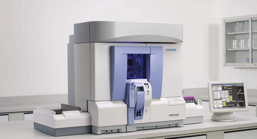
ADVIA® 2120i Hematology System
Quick Reference Guide
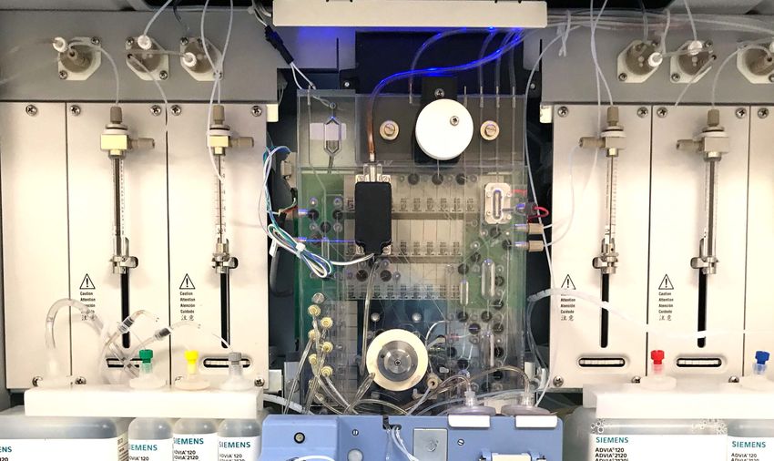
Table of Contents
System Overview.....................................3

Starting Each Shift...................................6

Quality Control.......................................11

Sample Processing.................................17

Methods................................................27

Scheduled Maintenance.........................32

Calibration.............................................41

Troubleshooting.....................................43

*Software Version 6.10.9/6.11.7 onwards

T 02006.001 | Effective date: 02/22/21
02-2021 | ©2021 Siemens Healthcare Diagnostics Inc.
                                                             2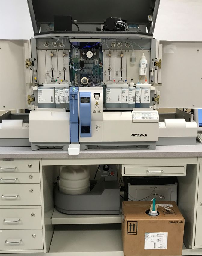
System Overview
 1. Laser Optical Assembly
 2. Perox Optical Assembly
 3. UFC (Unified Fluids Circuit)
 4. Overflow Bottle
 5. Manual Open-Tube Sampler (MOTS)
 6. Manual Close-Tube Sampler (MCTS)
 7. Touchpad
 8. Autosampler
 9. Waste
 10. Sheath/Rinse

                                       3

System Overview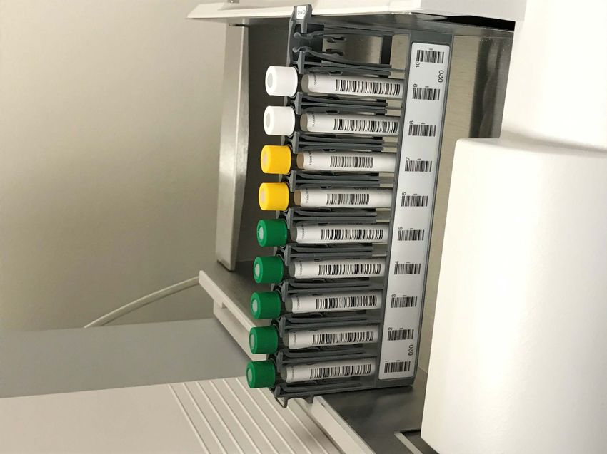
Unified Fluids Circuit (UFC)
1. Hgb Optical Assembly
2. Perox Reaction Chamber
3. Sample Shear Valve
4. 1000 µl Syringe
5. 50 µl Syringe
6. Baso Reaction Chamber
7. RBC Reaction Chamber
8. Retic Reaction Chamber

                               4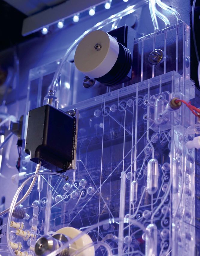
Software Overview
1. Status Line 1
   Sample ID, sample type, species
   (if applicable), selectivity and icons
2. Status Line 2
   Displays analyzer status and status-line
   messages
3. Menu Buttons
   Select to display a dropdown of system
   functions
4. Tabs
   Correspond to items on active menu
   button
5. Main Display Area
   Displays active screen
6. Shortcut Keys
   Customized quick links to frequently used
   menu items
7. Icons
   Service Log, Status Messages, Help,
   Notepad, Automation status (if
   applicable), and Autoslide status (if
   applicable)

                                               5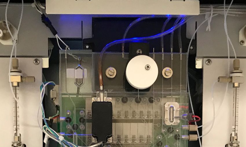
Starting Each Shift Tasks
1. Empty the Waste (if applicable).
2. Check the Overflow Bottle.
3. Check the Reagents.
4. Verify Background Counts are in range (green)
   on the Startup screen

      Note:
      If Background counts are out of range (red),
      select Refresh; if still out, perform System
      Wash followed by another Refresh.

                                                     6

                           Starting Each Shift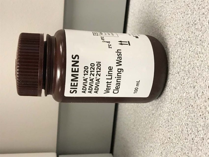
Empty Waste
Automatic Waste Removal
Important: The Autowaste assembly mode selector knob set to the automatic
mode eliminates the need to manually empty waste when it is connected to
waste disposal system.

If emptying of waste is needed with Autowaste Assembly, perform the following:

1. Turn the mode selector knob on the waste removal assembly tray from
   Automatic to Manual (this will take 2–5 minutes to empty).
                                                                                               Mode
2. Look for air bubbles in the discharge line. The air bubbles indicate the
                                                                                               selector
   container is empty.                                                                         knob
3. After the waste container is empty, turn the mode selector knob
   to Automatic mode.
                                                                                  Waste line   Vacuum
                                                                                               line
Manual Waste Removal
1. Make sure that the analyzer is not sampling.
2. Disconnect the waste line and the vacuum line. To do this, press the buttons                Level
   on the quick-release connectors and pull the lines straight up.                             switch
3. Disconnect the level switch sensor connector by pressing its button.                        sensor
                                                                                               connector
4. Empty the full container by opening the spigot into a drain in accordance
   with laboratory policy.
5. When the waste container is empty close the spigot.
   Verify spigot is closed securely.
6. Connect the waste line, vacuum line and level sensor                           Spigot
   to the emptied container.
                                                                                                     7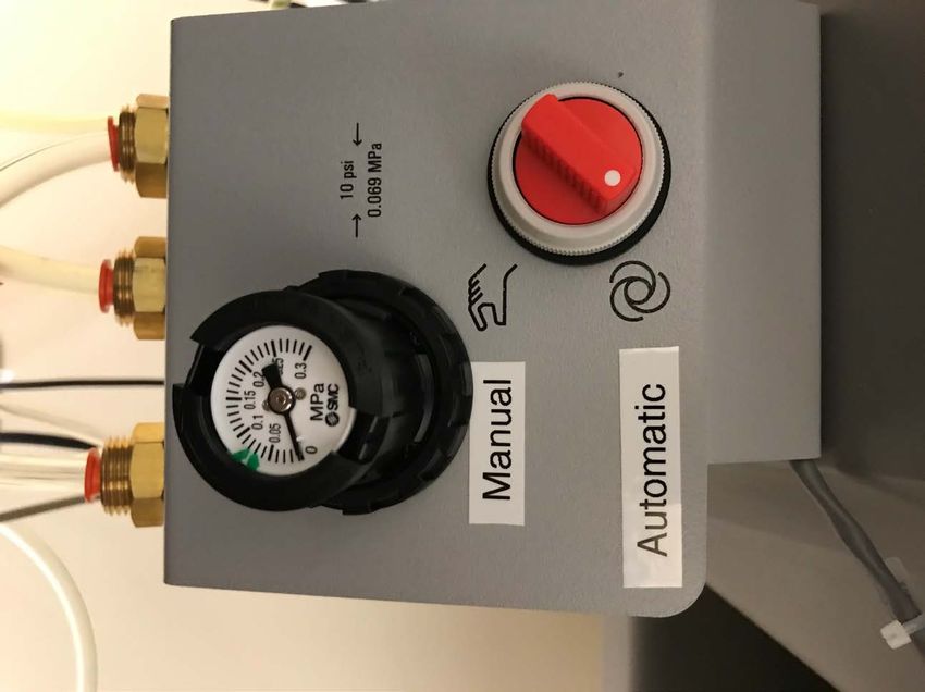
Check Overflow Bottle
1. Visually check the fluid level in the small
   overflow bottle (1).
2. Snap the bottle out of the clip, then remove
   the bottle cap (2). The lines (3) with the cap
   can hang loosely.
3. Empty the contents in accordance with
   laboratory policy.
4. Replace the cap, then snap the bottle in
   place.
5. The ends of the tubes should be at least 1.5
   inches (3.81 cm) from the bottom of the
   bottle.

                Note:
                If fluid consistently accumulates in
                the overflow bottle contact Siemens
                Healthineers Customer Support.

                                                       8
Reagent Installation
1. Select Logs menu
2. Select Reagent Log
3. Select Reagent Installation
4. Scan barcode of each reagent
   to be replaced.
5. Load reagents on the instrument.
6. Select Import Barcode
7. Select OK
8. Select Yes
9. Run Quality Control as per
   laboratory policy.

 ■ Green Adequate supply
 ■ Yellow Low supply
 ■ Red    No reagent

                                      Note:
                                      Must visually check the supply of ADVIA Defoamer.

                                                                                          9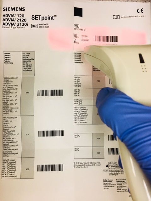
System Wash
1. Select Utilities menu
2. Select Hydraulics Functions
3. Select System Wash
4. Select Number of Cycles: default is 1
5. Select Start

      Note:
      System Washes have been automatically
      configured in the software.

                                              10
Processing Quality Control From the Autosampler
1. Analyzer Mode: Ready to Run.
If the Standby indicator is lit, press Standby on
the touchpad to bring analyzer out of standby.
2. Insert tube into rack with the Quality Control
product barcode label visible above the rack
barcode.
3. Load rack onto input queue with label facing
forward.
4. On the touchpad press Start/Stop Sampler.
11
Quality ControlProcessing Quality Control From the
Manual Closed-Tube Sampler
1. Analyzer Mode: Ready to Run.
If the Standby indicator is lit, press Standby on the
touchpad to bring analyzer out of standby.
2. Scan the control product barcode label.
3. Verify the control name is displayed on Status Line 1
before aspirating the sample.
4. Mix control well.
5. Insert tube upside down and push the tube into the
manual closed-tube sampler. Hold the tube parallel to
the sampler well wall.
6. The control will be automatically aspirated and the
sampling light will flash.
7. When the sampling light stops flashing, aspiration is
complete. Remove the tube.
12Processing Quality Control From the
Manual Open-Tube Sampler
1. Analyzer Mode: Ready to Run.
If the Standby indicator is lit, press Standby on the
touchpad to bring analyzer out of standby.
2. Scan the control product barcode label.
3. Verify the control name is displayed on Status Line 1
before aspirating the sample.
4. Mix control well.
5. Position the tube so that the sampler probe is
immersed into the sample.
6. Press the aspirate plate.
7. Sampling light will flash during aspiration. When the
sample light stops flashing, remove the tube from the
probe.
13Review / Edit and Validate Quality Control
1. Select Data Manager menu
2. Select Sample Control Panel
3. Select the Control from the Sample List
4. View Test Table Grid
Green: within +/- 2 SD
Yellow: > +/- 2 SD, < +/- 3SD
Red: > +/- 3 SD
5. Select Rev / Edit
6. Review results using the scrollbar to display all results.
7. Select Validate icon from right side toolbar
to validate results.
14Importing a New Lot of QC
1. Select Customize > System Setup (or Analyzer Setup) > Tools Modify > Control Dictionary
2. Insert the mini CD into the computer or scan barcoded package insert.
3. Select Import
4. A list of controls will display. Select the first control to import by clicking on the control name and select OK.
If a control file already exists with the same name, a window will display. Select Create.
5. In the Import Data screen, enter a code name for the control. The code name may be up to 6 characters and must be a unique
identifier. Select OK.
6. To activate the use of colors as indicators on the Sample Control Panel test panel, place a check mark next Test Panel. Select OK.
7. Continue process for all remaining controls. When all controls are imported, select Cancel to end importing.
8. To view a list of controls already defined in the Control Dictionary, type a ? In the Code box and select Enter.
Note:
If scanning barcoded package insert, scan the lot
number barcode located in the upper right hand
corner first followed by the rest of the parameters.
15Configuring the System to Print Final Control Reports
1. Select Customize menu
2. Select Tools View
3. Select Routine Parameter
4. Select Final Control Report
5. Select OK
16Sample Processing From the Autosampler
1. Analyzer Mode: Ready to Run.
If the Standby indicator is lit, press Standby
on the touchpad to bring analyzer out of
standby.
2. Insert tube into rack with the barcode label
visible above the rack barcode.
3. Load rack onto input queue with label facing
forward.
4. On the touchpad press Start/Stop Sampler.
17
Sample ProcessingSample Processing From the
Manual Closed-Tube Sampler
1. Analyzer Mode: Ready to Run.
If the Standby indicator is lit, press Standby on the
touchpad to bring analyzer out of standby.
2. Scan the sample barcode label or enter the sample ID in
Manual Sample ID.
3. Verify the correct Sample ID and Selectivity are displayed
on Status Line 1 before aspirating the sample.
4. Mix sample well.
5. Insert tube upside down and push the tube into the
manual closed-tube sampler. Hold the tube parallel to the
sampler well wall.
6. Sample will be automatically aspirated and the sampling
light will flash.
7. When the sampling light stops flashing, aspiration is
complete. Remove the tube.
18Sample Processing From the
Manual Open-Tube Sampler
1. Analyzer Mode: Ready to Run.
If the Standby indicator is lit, press Standby on the
touchpad to bring analyzer out of standby.
2. Scan the sample barcode label or enter Sample ID in
Manual Sample ID.
3. Verify the correct Sample ID and Selectivity are displayed
on Status Line 1 before aspirating the sample.
4. Mix sample well.
5. Position the tube so that the sampler probe is immersed
into the sample.
6. Press the aspirate plate.
7. Sampling light will flash during aspiration. When the
sample light stops flashing, remove the tube from the
probe.
19Processing a Sample in Manual Sample ID
1. Select Operations > Manual Sample ID
2. Enter Sample ID Number in Next Sample ID field.
3. Select Sample Type
4. Select Selectivity
5. Select Species (if applicable)
6. Select OK
7. Process sample in Manual Closed-Tube Sampler or Manual
Open-Tube Sampler mode.
20Creating Sample Workorder using Order Entry
1. Select Data Manager > Order Entry > Access
2. Enter SID # (additional sample identifier and
demographics may be entered if desired).
3. Select Tests to be processed.
4. Select OK
5. Select Cancel to complete Order Entry.
6. Barcoded sample can be scanned and processed.
Non barcoded sample will need to be processed using
Manual Sample ID.
21Run Screen Overview
1. Run Screen Menu Bar
Open, Configure, Hide, Display Off,
Arrange, Print and Help
2. Run Screen Header
Sample and Patient Identification
3. Routine WBC Differential
Including 6 Part Differential, nRBC, and
WBC Perox Count
4. Routine CBC Results
Complete Blood Count results
5. Histograms
Displays the uniformity of the cell-
counting rate
6. Cytograms
Graphic representation of two light scatter
measurements plotted along x axis and y
axis
7. Sample / System Flags and
Morphology Flags
22Sample Control Panel: Sample Status
1. Pending: A workorder has been created but
has not been resulted
2. Incomplete: Samples with no workorder, no
Sample ID, or results waiting to validated
3. C. Complete (Current Complete): Results
not yet printed or sent to the LIS
4. Complete: Validated sample records that the
system has printed and/or transmitted to the
host computer
5. All Complete: Sample ID numbers released
by the SID Reset in the End of Day window
6. Unmatched: Sample records with test
results which are not matched to a workorder
To Perform an SID Reset:
1. Select Customize > Tools View > End of Day
2. Select Yes to confirm workload is finished.
3. Select or verify the SID Reset checkbox is checked.
4. Select or verify the Moving Average Close Out check box is
checked if desired.
5. DO NOT select the QC Closeout checkbox unless directed by
laboratory policy.
6. Select OK to confirm and start SID Reset.
23Review / Edit and Validate Sample Results
1. Select Data Manager menu
2. Select Sample Control Panel
3. Select Sample ID Number
4. Select Rev / Edit
5. Review results using the scrollbar to display
all results.
6. Select Validate icon from right side tool bar
to validate results.
24Configuring Run Screen Report Options
1. Select Customize menu
2. Select System Setup (or Analyzer Setup)
3. Select System Options
4. Select Run Screen Options
5. Select Auto Print option
Print All
Print None
Print by Exception
6. Select Print by Exception option
All Morphology Flags
All Sample / System Flags
All High / Low Flags
All Flags
7. Select Save
25Configuring the System to Print Final Patient Reports
1. Select Customize menu
2. Select Tools View
3. Select Routine Parameter
4. Select Final Patient Report
5. Select OK
26RBC / Plt / Retic Methods
High Angle Scatter Detector
Measures: Density / HGB conc / Refractive Index
Zero Angle
Laser Measures: Retic Absorption / Staining
Low Angle Scatter Detector
Measures: Size / Volume
27
MethodsRBC / PLT/ Retic Methods
Large
Platelets
RBC
Low Angle / Volume (fL)
Low Angle / Volume (fL)
Ghosts
s
et
el
at
Pl
RBC
Fragments
High Angle / Hgb Concentration High Angle / Refractive Index
Coincidence
Scatter / Volume (fL)
Retics
RBC
Platelets
Absorption / Staining
28Hgb Transmission
1. Sheath / Rinse from previous cycle
2. Draining and refilling with sample and HGB reagent
3. Sample reading
4. Draining and refilling with Sheath/Rinse
Transmission
% Light Transmission
LightTransmission
5. Sheath / Rinse Baseline reading
%%Light
00 10.5
10.5 2525 2727
Time
Time (seconds)
(seconds)
29Baso Lobularity
1. Noise
2. Blast Cells
3. Mononuclear WBCs: Monocytes and Lymphocytes
4. Basophils
5. Baso Suspect
6. Saturation
7. Polymorphonuclear WBCs: Neutrophils and Eosinophils
Low Angle / Volume
High Angle / Density / Lobularity
30Perox Method
1. Noise
2. Nucleated Red Blood Cells
3. Platelets Clumps
4. Lymphocytes and Basophils
5. Large Unstained Cells (LUCs)
6. Monocytes
7. Neutrophils
8. Eosinophils
Scatter / Volume
Absorption / Staining
31Scheduled Maintenance
Weekly Maintenance
• Turn off the system.
• Wipe the outside of shear valve.
• Automatic Hydraulic Pathways Wash.
• Inspect Autosampler Centering Collar, clean if necessary.
Two Weeks Maintenance
• Clean Autosampler Centering Collar.
Monthly Maintenance
• Semi-automatic Vent Line Wash.
Two Months Maintenance
• Replace the RBC/Baso and Perox Sheath Filters.
6 Months Maintenance
• Clean the air-circulation filter.
Important:
In addition to these scheduled procedures, periodic inspections of the UFC pathways, vacuum shuttle, and reaction chambers are essential. If you
find buildup or dirt in any of the lines or chambers, clean the line or chamber in question.
32
Scheduled
MaintenanceWeekly Maintenance
Turn Off the System Wipe the Outside of
1. Select the Operations menu
Shear Valve
2. Select Log On / Off 1. Analyzer Mode: Off
3. Select Shut Down PC; computer will automatically power down. 2. Place paper towels under shear valve to
catch dripping water.
4. On the ADVIA touchpad, press OFF.
3. Rinse the outside of shear valve with squirt
5. Power Off the printer.
bottle filled with DI water.
4. Using a soft lint-free tissue, gently wipe
outside of shear valve.
Turn On the System (after maintenance
performed) 5. Remove paper towels and proceed with next
weekly maintenance task.
1. Restart system by powering on the computer first.
2. At the Windows Log On screen, enter the User Name and Password.
Select OK
3. The system opens the ADVIA 2120/2120i shell; select ADVIA 2120
4. On the ADVIA touchpad, press ON.
5. At the Log On/Off screen, enter the User Code and Password.
Select Log On
6. Power On the printer.
33Weekly Maintenance
Automatic Hydraulic Pathways Wash
1. Let two vials of ADVIA 2120/2120i RBC Flow Cell Wash
and five vials of ADVIA 2120/2120i Aspiration Pathway
Wash stand for 15–20 minutes to come to room
temperature.
2. Analyzer mode: Ready to Run
3. Load five vials of ADVIA 2120/2120i Aspiration
Pathway Wash onto the sampler rack.
4. Load two vials of ADVIA 2120/2120i RBC Flow Cell
Wash onto the sampler rack.
5. Load two vials of ADVIA 2120/2120i Perox Flow Cell
Wash onto the sampler rack.
6. Ensure the barcode labels on each tube are facing out
and are accessible to the autosampler barcode reader.
7. Press Start/Stop Sampler on the touchpad.
8. The system will automatically advance the sample rack
and begin the automated pathway washes.
9. Sample rack will be ejected out of the system.
10. Run QC as per laboratory policy.
34Weekly / Two Weeks Maintenance
Weekly Maintenance: Inspect Autosampler Centering Collar, clean if necessary
Two Weeks Maintenance: Clean Autosampler Centering Collar
Warning: The analyzer must be off; otherwise, personal injury from the needle may occur. To avoid personal injury and exposure to a
potential biohazard, cover the needle with the red needle cover immediately after it is removed from the centering collar. Be careful not
to bend the needle.
1. Analyzer Mode: Off
2. Inspect autosampler centering collar for debris and salt buildup.
3. Tilt the front cover down and remove the sample line from the bottom of the selector valve.
4. Loosen the thumb screws and tilt the autosampler aspirator assembly forward.
5. Pull up the spring-loaded knob, turn it a ¼ turn, then remove the centering collar by pulling it up and out.
6. Place the red needle cover over the needle.
7. Remove V43, V44 and V45 tubing from centering collar.
8. Place centering collar in 25% solution of 6% sodium hypochlorite and DI water for five minutes.
9. Remove any remaining residue with cotton swab and rinse with DI water.
10. Using a stylet, clean the fittings and the center bore of autosampler centering collar. Flush each port of the centering collar using DI water in a
syringe with 0.030 inch tubing attached.
(continue on next page)
35Weekly / Two Weeks Maintenance
Clean Autosampler Centering Collar (continued)
11. Reconnect V43, V44, and V45 tubing to centering collar.
12. Apply a small amount of Parker Super O-lube to the bottom of the centering collar taking care not to apply to ports or needle base.
13. Remove the needle cover and carefully replace the collar over the needle. On the autosampler centering collar, be sure to turn the spring-
loaded knob back to its original position.
14. On the autosampler, reposition the autosampler aspirator. Make sure that it drops firmly in place over the guide pins.
15. Finger-tighten the thumb screws and then reconnect the sample line to the selector valve.
16. Close the analyzer cover.
17. Turn analyzer power on, verify Background Counts, and run whole blood primers to verify system performance.
Parker Super O-lube
36Monthly Maintenance
Semi-Automatic Vent Line Cleaning Wash
1. Allow one bottle of ADVIA 120/2120/2120i Vent Line Wash to
stand for 15-20 minutes to come to room temperature.
2. Open the bottle of ADVIA 120/2120/2120i Vent Line Wash and
remove the vent overflow tubing from overflow bottle.
3. Insert two pieces of 12 inch (300.5 mm), 0.081-ID tubing onto
the RBC and Perox shuttle chamber vent line fittings.
4. Fully immerse each vent line tubing into the ADVIA
120/2120/2120i Vent Line Wash bottle.
5. Select Utilities > Hydraulic Functions > Clean UFC Vent Perox VSC vent line fitting RBC VSC vent line fitting
Lines and Chambers
6. Select All
7. Select Start
8. When the cleaning event is completed, place the tubing into a
container with 100 mL of DI water then select Start
9. Remove the tubing from the RBC and Perox shuttle chamber
vent line fittings.
10. Place all other tubing back into the overflow bottle then select
Start
11. Perform a background counts by selecting Operations >
Startup > Refresh. Verify background counts are within
range (green).
12. Run QC as per laboratory policy.
37Two Months Maintenance
Replace Sheath Filters
1. Analyzer Mode: Ready to Run
Locate filters by opening the system’s doors and refer to Location of the perox (1) and the
image on the right. RBC/baso (2) sheath filters
2. Remove the sheath filter from the mounting clip. Place
paper towels under the filter to absorb fluid from filter.
3. Disconnect the reagent line attached to the barbed fitting
and the input (top) port on top of filter.
4. Disconnect the luer fitting from the connector at the
output (bottom) port .
5. Hold the replacement filter by body and attach the luer
fitting connector at output port.
6. Connect the reagent line to the barbed fitting of input port
7. Insert the sheath filter into the mounting clip with the
input port up.
8. Prime the reagent lines by selecting Utilities > Hydraulic
Functions > Reagent Prime.
9. Select the Perox Sheath and Sheath/Rinse checkboxes.
10. Change Number of Cycles to 5
11. Verify filter is approximately 90% full; run two additional
prime cycles if needed.
12. Perform a background count by selecting Operations >
Startup > Refresh. Verify background counts are within
range (green).
38Six Months Maintenance
Clean the Air-Circulation Filter
1. Remove the filter by sliding the filter out of the frame.
2. Remove excess dust or lint from the filter by tapping it against
a clean, hard surface or by vacuuming.
3. Flush each side of the filter with a strong stream of water.
4. If the filter remains dirty, rinse the filter in a container filled
with warm water and mild detergent.
5. Rinse the filter with clean water, then allow it to air dry.
6. Replace the filter by sliding it back into its frame.
39Document Scheduled Maintenance
Update the Service Log
1. Select Logs > Service Log or select
2. Select the procedure performed.
3. Select Update Log
4. Review the information in dialog box.
5. Type User Code and/or add comments if desired.
6. Select OK
Export Service History
1. Select Logs > Service Log > Service History
2. Enter the Start Date and End Date from dropdowns.
3. At Intervention Type dropdown, select Scheduled
4. At Category dropdown, verify All is selected.
5. Select OK
6. Select Export
7. At the Export window, select a drive followed by Start
Note:
Do not attempt to export a log while the system
is processing samples.
40Calibration Wizard
Important:
Perform weekly maintenance before calibration procedure.
1. Select Procedures > Calibration > Calibration Wizard
2. Enter password and select OK (if required).
3. On Calibration Definition screen verify:
Type of Calibration
Primary Sampler Type
Calibration Parameters
4. Select Next and verify materials required.
5. Select Next and scan SETpoint™ Calibrator package insert, beginning with
the lot number barcode.
6. Select Import Barcode
7. Select Next and follow instructions on screen.
For Autosampler: Place rack on input queue and press Start/ Stop
8. When Autosampler is complete select Next
9. Follow directions on screen:
• Run calibrator 11 times with MCTS mode.
• Run calibrator 11 times with MOTS mode
10. Select Next to proceed to Calibration Acceptance screen.
(continue on next page )
41
CalibrationCalibration Data Review and Acceptance
1. The Calibration Acceptance screen will display Passed or Failed
2. For a Failed calibration, select grey box under Reason column.
3. Select Cal Data Review to review data and print reports
4. Select radio button to review each parameter:
• WBC
• RBC/PLT
• Retic
5. If calibration Passed, review Statistical Summary for each parameter.
Select Print Report for each parameter.
6. Select Back then select Accept Calibration
7. If calibration Failed, review and omit data points for parameter(s) that
failed in Cal Data Review screen. Omit outliers by removing red checkmark.
A minimum of 8 data points must be used in order to pass a calibration.
8. Select Back to view if calibration is Passed. Repeat omitting outlier data
point(s) if necessary.
9. If Passed, select Cal Data Review. Select Print Report for each Note:
parameter. Print Report for all parameters before selecting
Accept Calibration.
10. Select Back then select Accept Calibration
11. Run QC as per laboratory policy.
42Troubleshooting Probe Clog / Aspiration Failure Messages
Probe Clogs or Aspiration
Problems
Is problem sample-related?
YES NO
1. Check for sample clots Is problem in all modes?
2. Check for insufficient sample volume
NO
YES
1. Check for clogged needle or probe
1. Check vacuum (Utilities > Analyzer Status)
2. Check for clogged or kinked tubing to selector valve
2. Check / replace clot filter
3. Check for loose needle and/or connection at bottom of
3. Check for clogged or bent tubing to UFC from selector valve needle base or top of sample probe
4. Clean sample shear valve
5. Clean sample shear valve pathways
43
TroubleshootingReplace Clot Filter
1. Analyzer Mode: Standby 7. Orientation of the filter is not important.
2. Unscrew the filter tube fitting and tube assembly from the front 8. Reconnect the filter adapter fitting to the selector valve. Finger
of the selector valve. tighten.
3. Gently push the silicone sleeve to release the clot filter from the Important: Be very careful not to misthread the fitting.
filter adapter fitting. Misthreading could strip the valve which will prevent proper
4. Visually check the filter adapter fitting and the input port of the operation.
selector assembly for any debris or small particles. 9. Press Standby to return analyzer to Ready to Run mode.
5. If you find some debris, use a piece of lens tissue moistened with 10. Run a sample and visually check for air bubbles in the sample
water to remove it. line between the selector valve and the UFC block.
6. Wet the new clot filter with water and place it into the filter
adapter fitting.
Normal Clot Filter Overtightened Clot Filter
Selector
valve
Filter tube
fitting
44System Flags Troubleshooting Chart
RBCIFR /BIFR / RTCIFR PXIFR PX-NO
Combined with Combined with
1. Check reagents volumes / delivery 1. Check reagents volumes / delivery Other Flags nRBC flags
2. Check pressure and vacuum 2. Check pressure and vacuum
3. Check Sheath/Rinse delivery 3. Check perox sheath delivery
4. Perform RBC/Baso/Retic flowcell wash 4. Clean perox reaction chamber Troubleshoot
Other Flags
5. Check integrity of sample syringe 5. Perform perox flowcell wash
6. Backflush RBC/Baso/Retic flowcell 6. Check integrity of perox sample syringe
7. Clean shuttle pathways 7. Backflush perox flowcell
1. Check perox reagents
8. Clean perox shuttle pathways
volumes / delivery
2. Check pressure and vacuum
HGBIFR 3. Perform system wash
4. Perform perox flowcell wash
5. Check perox sheath delivery
1. Check reagent volumes / delivery 6. Check delivery of sheath/rinse
IF PROBLEM CONTINUES:
2. Check pressure and vacuum Call Technical Support 7. Check perox reaction
3. Check sheath delivery 1-877-229-3711 chamber temperature
4. Clean sample shear valve 8. Check perox hydraulics
and sample delivery
5. Clean shear valve pathways
9. Clean perox chamber
6. Clean reaction chamber vent line
45Clean the Shear Valve
1. Analyzer mode: Off
Important: Place paper towels directly under the shear valve to prevent fluid from dripping down into the analyzer.
2. Remove the knurled nut by turning counter-clockwise (1).
3. Remove the compression spring (2).
4. Remove the rotor (3).
5. Separate and remove shear face (4) by gently rotating front shear face.
Caution: Do not loosen or remove with sharp object
6. Place the front shear face in 6% sodium hypochlorite solution and soak ten
minutes. Rinse with DI water.
7. Rinse the rear shear face using a wash bottle filled with distilled water.
Caution: Do not use paper towel, gauze or cotton swabs on shear faces
8. Reassemble the shear valve with the faces wet. Verify the black line on the front
face aligns with the black line and A on back face. Smaller loops are at 9 and 11
o’clock and the large loop is at 5 o’clock.
9. Install the rotor by installing the drive pin in the hole on the right side of the front face.
10. Replace the spring and knurled nut.
11. Hand tighten nut.
12. Turn analyzer power on and verify Background Counts.
13. Run a whole blood primer and QC as per laboratory policy.
46Adjust Gains Wizard
Important:
Perform weekly maintenance before Adjust Gains procedure.
1. Select Procedures > Adjust Gains
2. Select Gains Wizard
3. Enter password and select OK (if required).
4. Select the radio button for the procedure to be performed. Perox and Baso can done with or without the Autosampler.
5. The software will default to the required number of aspirations.
6. Select Next
7. Verify materials required to perform gain adjustment.
Perox: ADVIA SETpoint™ Calibrator or TESTpoint™ Normal Control
RBC/Retic: ADVIA OPTIpoint™
Baso: Five Whole Blood Samples (less than 8 hours and must be from different donors)
Multispecies Users Only: Must select Dog or Human radio button for donor blood species used. MNx and MNy default values will display
later on Gain Reference Data screen.
8. Select Next
9. Gain Reference Data screen: For Perox and RBC/Retic, scan package insert barcode and select Import Barcode
10. Select Next
11. On the Run / Data Review screen, begin processing until the required number of aspirations are displayed.
12. Select Next
47Accept/Reject Gain Factors
1. On the Run/Data Review screen result. A
red check mark in the Apply column will
display on each row of data included in the
statistical analysis; to omit data, deselect
box.
For manual modes only, run additional
samples by selecting Run More and
following instructions on screen.
2. Select Next and review information on
the Gain Acceptance screen. To proceed,
Note:
select Accept Gains
For documentation, print
3. Before final gain acceptance, a final all raw data from Run /
verification is required; perform the Data Review screen
required verification run.
4. Review Verification Run data. For final
acceptance select Next and Finish.
5. Select Gain Factor Log to view and print
gain factors.
6. Select Exit to close.
7. Run QC as per laboratory policy.
48Troubleshooting CHCMCE Sample / System Flag
Is CHCMCE occurring on only one sample?
YES NO
Investigate SAMPLE
Investigate SYSTEM
related cause of flag
related cause of flag
Lipemia? Hemolysis? • Was a maintenance procedure just performed?
Cold Agglutinin?
• What was the last thing done on the instrument?
Hgb MCV MCHC RBC MCHC RBC MCV MCHC • If other flags appear with CHCMCE flag troubleshoot
Follow laboratory RBC parameters are not valid. Warm sample and rerun other flags first
procedure Follow laboratory procedure
Run controls to isolate the problem
Hgb
RBC MCV, CHCM
Low Results High Results
with bumpy mattress
Clean sample shear valve
Backflush the RBC/Baso/Retic flowcell
Prime HGB reagent line with Clean sample shear valve Clean Shuttle and Reaction Chamber
1. EZ Wash
Pathways
2. DI water
3. Hgbreagent (see next page)
49Troubleshooting CHCMCE Sample / System Flag
Backflushing the RBC/Baso/Retic Flowcell Clean the Shuttle Pathways and Reaction
1. Select Utilities > Exerciser > Valves
Chamber
2. Unscrew the white fitting of Valve 23 1. Select Utilities > Exerciser > Valves
(upper middle valve above the RBC syringe). 2. Unscrew the white fitting of Valve 23
3. Attach the white fitting to a flowcell cleaning syringe filled with a 3. Open V9 and then push the syringe to fill the RBC chamber with
25% solution of 6% sodium hypochlorite and DI water. 25% solution of 6% sodium hypochlorite and DI water; open V10 to
4. Disconnect the sample tubing fitting from top of sample syringe drain.
and place into a beaker to catch the fluid. 4. Close V9 and V10.
5. Gently push the plunger on the syringe to flush the 25% solution 5. Repeat steps 3 and 4 with DI water.
through the flowcell.
6. Refill the syringe with the 25% solution.
6. Repeat with DI water.
7. To flush the RBC Vacuum Shuttle Chamber (VSC), open V20
7. Reattach the sample tubing fitting and the Valve 23 white fitting. and V22. Fill the chamber then empty the chamber by opening
V21. Close V21.
V23 Fitting 8. Repeat step 7 with DI water.
9. Reattach the Valve 23 white fitting.
Sample
tubing 10. Select the Analyzer Status tab to exit Exerciser.
fitting 11. Perform one System Wash and run QC as per lab policy.
50Siemens Healthcare Diagnostics, a global leader in clinical ADVIA, SETpoint, TESTpoint and OPTIpoint are trademarks of
diagnostics, provides healthcare professionals in hospital, Siemens Healthcare Diagnostics Inc. All other trademarks are
reference, and physician office laboratories and point-of-care the property of their respective owners.
settings with the vital information required to accurately
diagnose, treat, and monitor patients. Our innovative portfolio 02-2021 | All rights reserved
of performance-driven solutions and personalized customer ©2021 Siemens Healthcare Diagnostics Inc.
care combine to streamline workflow, enhance operational
efficiency, and support improved patient outcomes.
T 02006.001 | Effective date 02/22/21
This quick reference guide, and the software described within,
are copyrighted. No part of this may be copied, reproduced, Note: This document is for supplemental
translated, or reduced to any electronic medium or machine- use only, and not meant to be used in
readable form without the prior written consent of Siemens place of primary technical materials.
Healthcare Diagnostics.
Global Siemens Headquarters Global Siemens Healthcare Global Division
Siemens AG Headquarters Siemens Healthcare Diagnostics Inc.
Wittelsbacherplatz 2 Siemens AG 511 Benedict Avenue
80333 Muenchen Healthcare Sector Tarrytown, NY 10591-5005
Germany Henkestrasse 127 USA
91052 Erlangen www.siemens.com/diagnostics
GermanyYou can also read