CBC - Cable Release Operating Manual - MannTek
←
→
Page content transcription
If your browser does not render page correctly, please read the page content below
Operating Manual
CBC - Cable Release

                      Version 200817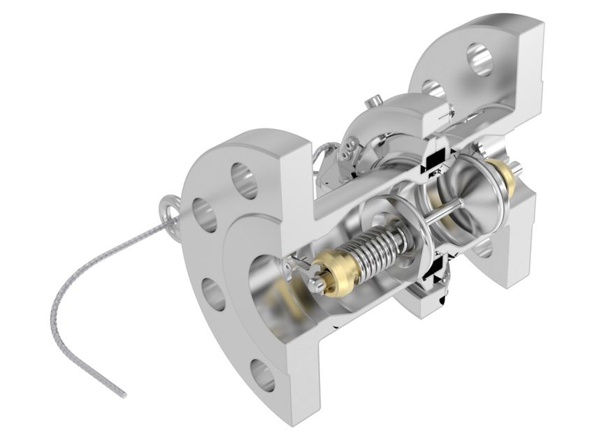
FOREWORD
This operating manual applies to the persons using the Cryogenic Breakaway Couplings.
It is very important to read and understand this operation manual before use of this coupling.
Become familiar with the unit’s operation, applications and limitations. Be particularly aware of
its specific hazards. Store this manual in a clean area and always at a readily available location.
Additional copies at no charge can be obtained through written requests.
READ THE COMPLETE DOCUMENTATION
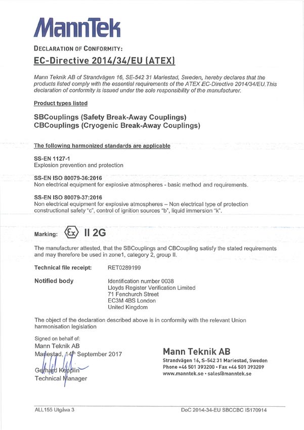
The base for this manual follows the EU-Directives:
Pressure Equipment Directive 2014/68/EU of 15 May 2014
Potentially Explosion Atmosphere Directive 2014/34/EU of 29 March 2014
• Do not make modifications that are not authorized by the manufacturer.
• Read and respect all warnings and instructions provided to you.
• Use only original MannTek spare parts for maintenance.
SUMMARY OF REVISIONS
Date of Change Description
2020-08-17 1st edition
Version 200817 2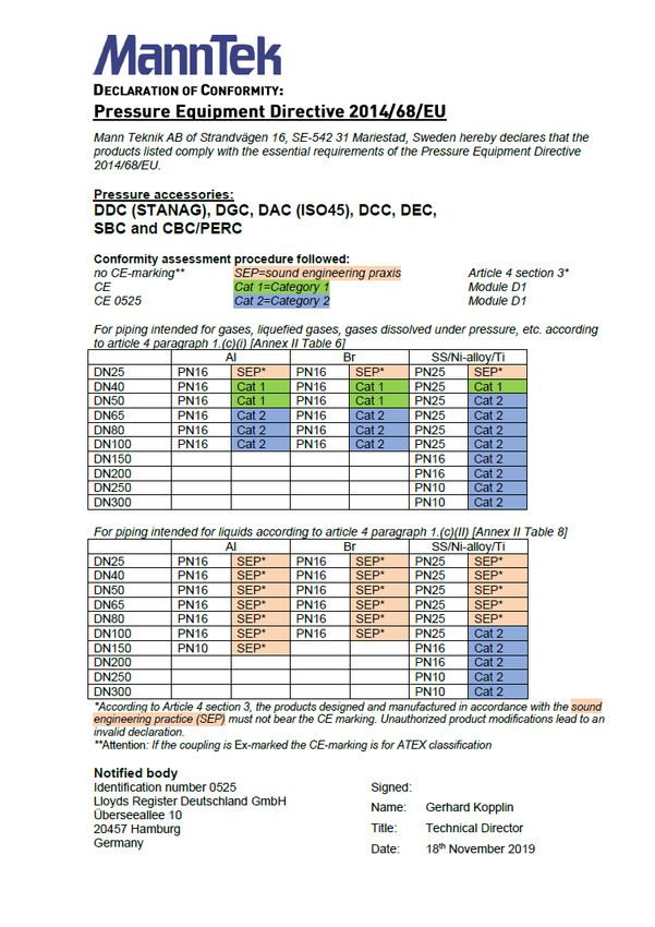
TABLE OF CONTENT

     Foreword
               								2
     Summary of Revisions						    2
     Table of content							3
     1 Introduction								4
     2 General Safety Rules						  7
     3 Transport and Storage						 8
     4 Installation								9
     5 Operation								11
     6 Maintenance and Repair						12
     7 Applicable Documents						17

Version 200817                          3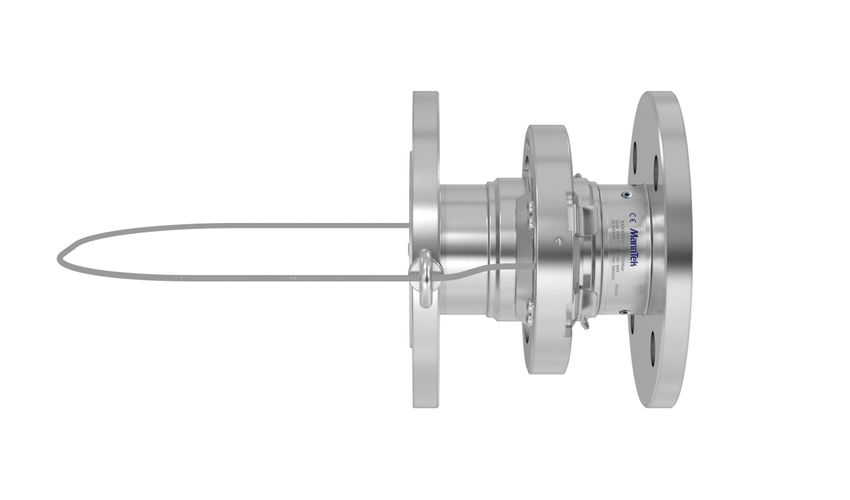
1      INTRODUCTION

     INTENDED USE
     The Cryogenic Break-Away Coupling (CBC) acts as a safety
     component in the supply line of mobile systems, preventing
     damage to personnel and environment, instead of a supply hose or
     pipe rupture during filling or emptying due to a change in location
     of the tank. The coupling valves on the tank and on the supply line
     immediately close whenever the CBC halves separates.

     The CBC is specially designed for trouble free operation in
     cryogenic service conditions down to -196ºC. Reliable and safe
     operation is dependent upon the correct installation and handling of
     the equipment. Regular and appropriate maintenance is essential
     to ensure both safety and reliability over the life of the equipment.
     Take care that the product is only used inside the limits of the
     following product specification.

     PRODUCT SPECIFICATION
      Product Name:            Cryogenic Breakaway Coupling
      Sizes:                   2“, 2½“, 3“, 4” and 6”
      Thread Connection:       NPT-Thread ANSI B1.20.1
      Flange Connection:       Flange EN 1092, ANSI B16.5
      Other Connection:        On request
      Material:                EN 10272 – 1.4401/1.4404+AT
                               ASTM A479 – S31603 (316L)
      Working pressure:        10 bar / 16 bar / 25 bar / 150 psi / 300 psi
      Max test pressure:       16 bar / 25 bar / 40 bar / 240 psi / 450 psi
      Temperature range:       -196ºC to +80ºC

Version 200817                                                                4
TECHNICAL DATA
     Table 1: Nominal Widths, Weight and Dimensions [mm]

       Nominal width       Connection         kg (stainless)        D [mm]           L [mm]
                            2“ Thread               2,6               114              178
                 2“
                            2“ Flange               7,3               165              178
                           2½“ Thread               7,4               140              251
                 2½“
                           2½“ Flange              13,2               191              214
                            3“ Thread               8,5               174              279
                 3“
                            3“ Flange              15,1               210              222
                            4“ Thread              15,5               211              320
                 4“
                            4“ Flange              20,7              254               239
                            6“ Thread              46,8              304               400
                 6“
                            6“ Flange              57,6               318              384

     Table 2: Materials

         Component         Material no.            Standard              Operating temperature
          Housing            1.4401           EN 10272 – 1.4401+AT
                                                                             -200°C to 250°C
         Check valve         1.4401           EN 10272 – 1.4404+AT
           Spring            1.4401            EN 10270 – 1.4401             -200°C to 250°C

     TRIGGERING FORCES
     Table 3: Forces on the pull cable (calculated)

                   Nominal width                      DN 50    DN 65    DN 80    DN 100   DN 150
       Release force at 25 bar nominal pressure       0,5 kN   0,6 kN   0,8 kN   2,0 kN   3,6 kN

Version 200817                                                                                     5
IDENTIFICATION PLATE
E.G. for CBC 2” - 2” ANSI Cl.300
Industrial Type
Article no: OC258D44*
Seal: PTFE
Mtrl: Stainless Steel
Size: DN50 – 2“
*For key of article no. please ask for explanation list.
SCOPE OF DELIVERY
1 pcs OC258D44 Cryogenic Wire Release Coupling
In case of flange connection gaskets and bolts to mount the coupling into the application is
not part of the delivery. For NPT thread use PTFE tape for sealing (see chapter 4.2).
Version 200817 62 GENERAL SAFETY RULES
PLEASE NOTE!
For a safe operation, read this manual completely before operating this
product.
Failure to follow the warnings may result in serious personal injury, property
damage, leakage or unexpected separation.
Before you install any MannTek equipment it is essential to check that the material and
performance specifications are acceptable for your specific application. The pressure ratings
and primary materials of the couplings are clearly indicated on the identification plate of each
MannTek product. A drawing showing the materials of construction relating to each individual
component is available upon request. Specification checks should always be carried out
before the product is supplied, but if unsure, ask!
As with all equipment, a check should be made to ensure that the installation fulfils the
requirements of applicable prevailing industry, local, national and international standards.
Particular attention should be paid to pressure ratings, safety factors and the position of
upstream and downstream affiliated closures.
SAFETY INSTRUCTIONS
Wear proper safety clothing consists of thermal gloves, full face shield
approved for cryogenic use and solid shoes capable to withstand cryogenic
spill whenever operating Cryogenic Break-Away Couplings.
Make sure the operating space is clear to avoid accidental contact with others
and the coupling interface is clean and dry. Use dry air or nitrogen to blow out
the coupling interface.
Do not use the CBCoupling in any way, not described in the specification.
The user is responsible to comply with all applicable federal, state and local
laws and regulations.
Do not operate the CBCoupling if there is any visible damage. Stop
immediately if leakage occurs.
Make sure that there is no trapped liquid or excessive pressure.
Authorized and qualified personnel must carry out all assembly and
maintenance operations as described in this operating manual.
Version 200817 73 TRANSPORT AND STORAGE
The product may only be transported or stored absolutely clean. Suitable protection must
be used for both openings to ensure no damage occurs to the surfaces/sealed areas.
The storage location must guarantee adequate protection from corrosion or extreme
temperatures.
DELIVERY CHECK
• Check for any transportation damage. If so report this immediately to the forwarder.
• Check that the products and quantities are in accordance with the delivery note.
COMPLAINTS / RETURN OF GOODS
• If returning goods please contact Mann Teknik AB to receive a Complaint Report form.
• Complete the form with as much details as possible.
• Return the goods with the Complaint Report attached on the outside of the package!
STORAGE
Store coupling in a dry, dust free, dark place, in ambient temperature.
Version 200817 84 INSTALLATION
INITIAL OPERATION
The correct installation of all MannTek products is essential to ensure safe and satisfactory
operation. Checks should be made to ensure that the fitting of MannTek products does not
interfere with the correct operation of affiliated equipment (i.e. isolation valve, excess flow
valves, etc). Before securing the flange or thread connections to mating equipment (i.e. hose,
loading arm and storage tank) ensure that no foreign objects, dirt, grit, water (moisture) etc.
are present in the coupling.
All flange and thread connections should be made without imparting excessive strain to the
equipment. All gaskets and sealing materials used to make the permanent connection should
be of suitable material.
Each MannTek product is designed to take reasonable axial loads associated with good
handling practice but is not designed to accept continuous excessive load values associated
with maladjustment or poor installation. Continuous excessive strain will equate to increased
component wear and possibly premature failure if not corrected.
When MannTek equipment is used with hoses, attention should be paid to hose length to
ensure correct handling characteristics. The hose assembly should be designed such that
the minimum hose length is supported by the coupling or the operator. Hoses should be of
sufficient length to ensure operation well within the stipulated hose minimum bend radius up
to the maximum operation envelope.
INSTALLATION
When installing MannTek equipment to new pipe work, tanks, etc. ensure the system is free
from debris that may be transferred through the coupling. Where the hose or loading arm
assembly is the primary static dissipation or earth route, the electrical continuity value of the
assembly shall be checked to ensure regulatory compliance. Special attention should be paid
to the balancing of loading arms. It is usual for loading arm balance settings to account of
weight variations due to differences in the full / empty cycle. The loading arm should be set to
balance in the condition present at the time of connection.
PLEASE NOTE!
Note when installing
Direction of release
Max deciation of pull direction is 50° from center
Version 200817 9Before mounting the CBCouplings ensure that trapped liquid never can occur in the
installation. In combination with a Dry Cryogenic Coupling or Emergency Shut Down Valve
measures shall be taken to ensure that no liquid can be trapped in any operating mode.
Then the CBCoupling can be installed directly in the product line and is ready for use after
removing the transport protection.
The installation is as follows:
• Remove the packaging.
• Check the coupling for damages before mounting.
• Ensure that the product line is empty and all valves are closed before you assemble the
✓ ×
coupling into the line.
• To prevent damages during mounting a suitable wrench should be used for the intended nut
flats on the coupling (threaded connection) or the bolts (flanged connection).
Use always a fitting wrench to mount the coupling to Torque forces should
a hose, a pipe or a tank. Tighten the fitting using the never be transferred via
wrench on the respective side where the connection is the CBCoupling and the
made. breaking pins.
The start-up may take place only when the CBCouplings has been mounted as instructed and
the necessary function tests and leak tests have been conducted by the approved authorities.
Version 200817 105 OPERATION
GENERAL NOTES
Operators are obliged to provide qualified and trained personnel familiar with the handling of
supply pipes, safety couplings, any fluid being pumped as well as its danger potential. Such
staff must also be familiar with the applicable safety regulations and the regulations of the
employer’s liability association.
DAILY VISUAL INSPECTION
All couplings should be inspected at the start of each day’s operation. Check for leakage and
any obvious physical damage (such as impacts, etc.).
DISMANTLING
When the CBCoupling is taken out of service, the risk of liquid or gas spurting out should be
taken into consideration. Special protective measures such as personal protection equipment
must therefore be adopted.
HOW TO DISMANTLE:
a. Wear suitable personal safety equipment.
b. Make sure that the coupling is depressurized and empty.
c. Unscrew coupling always with a wrench fit for purpose.
IMPROPER USE
The equipment should never be used in the case of visible damage or where there is prior
knowledge of damage that may lead to malfunction.
Version 200817 116 MAINTENANCE AND REPAIR
6.1 GENERAL INFORMATION
The CBCoupling consists of two housing halves with a check valve in each. The housings are
held together by two pressure clamps and a support ring during normal operation. The two
check valves support each other during normal operation and keep the conduit open.
2 Positioning body halves
3 1 Release cable
8 2 Outer support ring
1 3 Pressure clamp
4
4 Coupling flange
5 5 Outer Sealing
6 Spring-activated piston
7 Piston Sealing
8 Body; coupling halves
7
6
In case the tank wagon rolls away or someone forgot to disconnect the supply line before the
truck drives off, the CBC is activated as follows:
Before the supply line is stressed by undue external forces the support ring is pulled out
by a pull cable running parallel to the supply line which releases the pressure clamps.
The coupling halves are separated from each other and the spring-loaded check valves
instantaneously close both ends of the line. One half of the coupling remains firmly connected
to the tank wagon while the other half of the coupling re- mains connected to the supply line.
This prevents the outflow of liquids or gases from both product carrying ends of the line.
Maintenance tasks, to put the released coupling back into service, may be performed only
by trained personnel from an authorised professional workshop. All measures necessary
for inspection, maintenance and repair must be carried out in accordance with the national
regulations of the country where the system is installed
Version 200817 12MAINTENANCE AND SERVICE INSTRUCTION
Always depressurise the system and rinse off the parts before beginning any
maintenance work. Use protective goggles.
Use tweezers and wear gloves which are sufficient for cryogenic applications.
Do not touch adjacent parts with unprotected hands. Rinse off the parts once
again before starting the “daily inspection”
DAILY INSPECTION
All couplings should be briefly inspected at the start of each day’s operation. Check for dirt,
seal damage and any obvious physical damage (such as impacts, etc.).
REGULAR SERVICE
Regular service interval is very much depending on local regulations and application
conditions. If nothing else is specified and it is a new application with unknown parameters
we recommend to make a first service after one year and decide then depending on the
inspection result about further intervals.
The service procedure shall be as follows:
1. Exchange seals.
2. Replace worn or damaged components.
USE ONLY ORIGINAL MANNTEK SPARE PARTS FOR MAINTENANCE.
SPARE PARTS AND TOOLS
Example for a 3” coupling (NC4…)
Seal kit (O-NC4-06)
Bolt kit (S-NC4-44-xx)
xx means the break force on the bolt. The break force can be found on the ID plate and on
each bolt.
Version 200817 13AFTER RELEASE
When the coupling should go into service there is a danger that the
fluid will spurt out. Special protective measures such as personal
protection equipment must therefore be adopted. Always ensure
the system is cleaned in the proper manner. After cleaning, remove
any residue from the cleaning agent.
a. Wear suitable personal safety equipment.
b. Make sure that the coupling is depressurized and
empty.
c. Clean coupling before disassembly (use cleaning
agent suitable for the pumped fluid).
DISASSEMBLE
Unscrew the three screws that lock the spindle steering.
There is a distance pin in the piston protruding from the
housing.
For disassembling a support plate with a hole in
the middle will avoid any damage of the piston.
Tool: Screwdriver
DISASSEMBLE
Press down the spindle steering and turn it free. Release it
carefully
Piston guide is spring loaded. Risk of injury.
Using our special tool makes work easier and therefore increases
safety.
Tool: TOOL-020
Repeat the same procedure with the second half.
DETAILD PARTS AFTER DISASSEMBLING
Take out all the parts from the body
Pos.2 – Piston
Pos.4 – Spindle steering
Pos.5 – Spring cap
Pos.7 – Spring
Pos.18 – Body
18 4&5 2 7
Version 200817 14MOUNTING PISTON
The piston is bigger in diameter than the three brackets for
the piston guide.
Introduce the piston as shown. Put it into a relaxing position
in the valve seat. Take care; the piston is sticking out on the
other side.
For assembling a support plate with a hole in the middle will
be helpful.
REASSEMBLE
Set both halves onto each other and press them carefully
together.
It is important that the bodies align to each other
when pressing the halves together. Do it carefully,
not to destroy the lip-seal.
Using a press and a fixture makes work easier.
FIX THE CLAMPS AND RING
Place the clamps (b) over the coupling flanges smaller
c diameter (d) and put the ring (a) over the clamps to hold
a them in place. Make sure that the bolts (c) are placed on
either side of the clamps. After the coupling is completely
reassembled provide a pressure test according to test
procedure on page 8.
b
d
c
NOTE WHEN INSTALLING
The direction of pull is marked on the release ring.
The max deviation of the pull direction is 50° from
center.
Loctite® is registered trademark of Henkel.
Version 200817 15PRESSURE AND TIGHTNESS TEST
After each service a tightness test of each coupling is mandatory.
The following test parameters are in accordance with EN12266, EN14432 and ISO5208:
Shell tightness test (air/N2): 6 bar +/- 1bar stop time 60 s.
Instead of dry air / N2 we recommend making the tightness test with liquid nitrogen or with
LNG.
If a pressure test should be achieved for the coupling mounted in an assembly, follow the
respective test instructions for the equipment but do not exceed our recommended maximum
test pressure of the coupling which you will find in the following table. If testing with higher
pressure is necessary, please ask our sales department for a special test bolt kit.
It is not recommended to use liquids for the tests which will freeze under operation with LNG.
If so, it must be guaranteed that the coupling is completely free of liquid before it will be used
in operation.
Approved couplings get stamped on the piston.
Number tested: 100%
STORAGE
Store coupling in a dry, dust free, dark place, in ambient temperature.
Version 200817 167 APPLICABLE DOCUMENTS
EU Guideline 2014/68/EU PED, 2014/34/EU ATEX
International Transport of Dangerous Goods ADR, RID, IMDG
Test standards EN12266, EN14432, ISO5208
Thread standards ISO 228, ANSI B1.20.1 - Flange standards EN 1092, ANSI B16.5
For use in other countries:
Respective national requirements and guidelines
DECLARATION OF CONFORMITY
Mann Teknik AB
Strandvägen 16, S-54231 Mariestad, Sweden
Phone +46 501 393200 Fax +46 501 393209
www.manntek.se sales@manntek.se
© Copyright 2020 Mann Teknik AB. Mann Teknik AB reserves the right to make changes at any time in prices,
materials, specifications and models and to discontinue models without notice or obligations.
Version 200817 17You can also read