Instruction Manual - Cozy Cabin Heater Propane Bottom Assembly - Dickinson ...
←
→
Page content transcription
If your browser does not render page correctly, please read the page content below
Cozy Cabin Heater Propane Bottom Assembly
                             #10400

              Instruction Manual
This manual must be read and the requirements carried out
          to ensure satisfactory performance.

DICKINSON MARINE RESERVES THE RIGHT TO MAKE CHANGES TO PRODUCTS
                   OR DOCUMENTS AT ANY TIME

                     Serial#___________________

           www.dickinsonmarine.com ~ info@dickinsonmarine.com
                         Form#7.2-69 Issue#2
WARNING!
   THIS IS A LOW PRESSURE
   PROPANE GAS APPLIANCE.

   YOU MUST HAVE A
SEPARATE 11” W/C LOW
 PRESSURE REGULATOR
INSTALLED CORRECTLY
  OR OPERATION WILL
      RESULT IN A
 DANGEROUS FIRE AND
  WILL DAMAGE YOUR
         UNIT.
**PLEASE READ YOUR INSTRUCTION MANUAL
     BEFORE USE OF THIS APPLIANCE**
 DICKINSON MARINE PROPANE BOTTOM ASSEMBLY
        www.dickinsonmarine.com ~ info@dickinsonmarine.com
                      Form#7.2-69 Issue#2
Keep your proof of purchase and product serial number for warranty

INTRODUCTION

Thank you for selecting the Dickinson Marine Cozy Cabin Heater. Your unit was
carefully inspected and tested at our factory. We take pride in producing one of the finest
heaters manufactured for marine use.

Because of the continuing refinement of our product designs, your heater may possess
features that are not discussed in this manual. We have tried to supply all the information
you might need, so please take time to read this manual before installing and using your
Cozy Cabin Heater.

Dickinson Marine advises strongly against unauthorized modification of this product, but
we do encourage you to correct problems which may arise by undertaking the simple
repairs and maintenance described in this manual.

The most important reason to carefully read this manual is that many of its instructions
are essential to the safe operation of your Cozy Cabin Heater.

Any recommendation or advice by Dickinson Marine, or any of its employees, is
given with the understanding that it is solely as an accommodation to the customer,
and should not be relied upon by the customer without an independent verification
of its applicability to the customer’s particular situation.

SAFETY AND INSTALLATION

General
The Cozy Cabin Heater, Bottom Assembly #10400, is designed to be fuelled only by
propane (LPG). If compressed natural gas (CNG) is used in this heater the burner flame
will be inadequate for heating.

Propane is an excellent and convenient fuel if used in accordance with rules, safety and
common sense. If these rules are ignored, there is a danger of fire and explosion. We
have done our best to design and construct your Cozy Cabin Heater with safety in mind.
You can do your part by following these rules.
Propane (LPG) Fuel System

1.     Buy your cylinder, gauge, master solenoid valve and hose from a reputable marine
       dealer, or your local LPG service center. We specifically recommend that only a
       high quality regulator be used with your Dickinson Marine Cozy Cabin Heater. It
       must be set at 11” water column. (In Europe this is sometimes expressed as
       .0274bar and is close to .5psi).

                     www.dickinsonmarine.com ~ info@dickinsonmarine.com
                                   Form#7.2-69 Issue#2
2.      Locate the cylinder and regulator in a locker vented to the open air (preferably on
        the deck or cabin top) isolated from the hull interior by a vapor tight enclosure.
        Refer to local codes or Coast Guard requirements for details.

3.     Propane is heavier than air. Therefore, the locker in which the cylinder is
       installed must be vented at the bottom. Position the vent above the water line, and
       at least two feet from any hull opening to the boat interior or engine exhaust.
We recommend the installation of a vapor monitor on your boat with all propane fueled
devices.

4.      Propane is a two-phase (liquid/vapor) fuel, and only vapor withdrawal from the
        tank is safe. Firmly mount the cylinder, right side up, to ensure that liquid
        withdrawal does not occur.

We recommend that a solenoid valve, which can be controlled by a switch located in your
cabin, be installed next to the manual cylinder valve. The cylinder valve outlet and the 12
VDC solenoid valve should be clean and dry when they are connected to each other.

5.      Use Teflon tape or Loctite to seal these connections being very careful to not
        introduce any foreign materials into the system that can plug the tiny appliance
        orifices.

6.      A 0-300 psi (0-20 bar) pressure gauge may be installed between the bottle and the
        regulator to give bottle pressure.

7.      Install the regulator downstream from the pressure gauge with its vent port
        pointing downward, which prevents the pressure vent from getting plugged.

     ** In some cases the solenoid valve is installed on the low pressure side of the
        system (i.e. after the LPG regulator). See solenoid manufacturers' instructions
        for proper installation.

                     www.dickinsonmarine.com ~ info@dickinsonmarine.com
                                   Form#7.2-69 Issue#2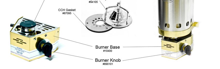
Recommended LPG System Installation

8.     Starting from the propane tank itself, the fuel line attachments should occupy the
       following positions: (a) the tank shut-off valve, (b) the pressure gauge, (c) the
       regulator, (d) the solenoid valve.

9.     Affix the caution label plate supplied with your Cozy Cabin Heater in the
       immediate vicinity of the gas cylinder in a place where it will be plainly visible.

10.    The LPG supply line should be 3/8” (10mm) soft copper line, on which your
       plumber will install the flare nuts when you tell him how long to make it. It can
       also be a flexible fire-resistant hose, UL or CGA approved hose for use with
       propane, complete with 3/8” (10mm) flare nuts on each end. A single continuous
       line or hose without couplings or tees is a must. Every connection is a potential
       leak.

11.    Because every connection is a potential leak, the fuel line should be one
       continuous length of hose or tubing. Do not make a “T” off and fuel line between
       an existing appliance and the gas cylinder to feed another appliance. (You may
       install a “T” connection only within the fuel tank’s enclosure, so any leakage is
       dissipated overboard)

12.    Be sure you do not kink the hose or piping connecting the regulator with the
       heater by bending it too sharply during installation.

13.    Protect the hose against vibration and damage by securing it tightly to bulkheads
       and hull side with non-corrosive ties or clamps which will not cut, abrade or pinch
       it.

14.    Fuel lines must be protected by close-fitting grommets and sealants where they
       pass through decks or bulkheads, and the passage must be made vapor-tight. They
       should be installed so that they are readily accessible to inspection.

Fuel System Testing

If you install a low pressure Guage (0 to 15 PSI) after the pressure regulator you can
check for leaks by watching the pressure guage. To do this open the manual cylinder and
solenoid valves and make a note of the reading on the pressure gauge. Now close the
manual cylinder valve. The pressure should remain constant for at least 10 minutes. If it
does not, gas is leaking out of the system.

The leak(s) should be located by applying a mixture of liquid detergent and water to all
connections and other suspect points and checking for bubbles.

                    www.dickinsonmarine.com ~ info@dickinsonmarine.com
                                  Form#7.2-69 Issue#2
Do not attempt to locate leaks by using an open flame. Repair and re-test the system
before putting it into operation.
For more detailed general instructions on the installation of Propane systems on boats,
please refer to the American Boat and Yacht Council’s pamphlets #A-1 and #A-22
respectively. These pamphlets may be ordered directly from A.B.Y.C.
If you are replacing an older diesel/kerosene or an older propane version you may need to
drill out the old pop rivets with ( 1/8” drill ) connecting the burner bottom base to the
heater. Place the new base so the bottom of the base is flush with the bottom of the heater
and mark 2 holes on each side of the heater flanges. Drill with 3/16” and use 8-32 or M6
size screws and nuts. Some versions may have the 4 holes already tapped to fit 8-32
thread screws.
OPERATING INSTRUCTIONS
1. The first time you use your heater you will have to purge the air out of the supply
lines before it will light. Turn the knob to the “pilot” position and push in. You
may hear a hissing sound. Keep the knob pushed in until you smell gas, then
immediately turn the knob to the “OFF” position. Wait a few moments before
lighting to allow any excess propane to dissipate. Purging air can take quite a
while if you have a long supply line. This is only necessary when fuel supply is
disconnected.
2. Do not forget to remove any plastic before using.
3. Push control knob in, hold it in and turn counter-clockwise to pilot position. If this
is the first time or the first time in a while that the heater is being used, push in the
knob on the pilot setting for 60 second or until you smell gas. This will purge the
pilot light parts of air. Then, with the knob depressed on pilot, push in the black
spark-ignition button to ignite pilot. Once ignited, hold control knob in for 10 to
20 seconds. If it does not light, repeat this procedure. If it still does not light,
purge the line some more or hold match over pilot.
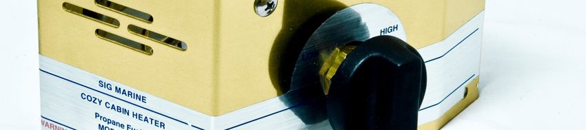
4. When the oxygen depletion pilot flame comes on, you must hold the knob in for
10 to 20 seconds. During this time the pilot flame heats up the thermocouple.
When the thermocouple is hot it generates a small amount of voltage, which will
energize a small solenoid coil inside the gas valve. This energized coil permits the
valve to regulate propane into the burner.
5. Adjust the burner by turning counter-clockwise to Low. To extinguish, turn the
knob all the way clockwise to Off.
www.dickinsonmarine.com ~ info@dickinsonmarine.com
Form#7.2-69 Issue#2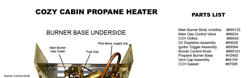
Caution: This heater consumes oxygen. You must supply sufficient outside
       air to replace the oxygen used by the heater. This unit is equipped with an
       oxygen depletion device which will turn off the pilot flame when the oxygen
       level drops to 95% of normal. This, in turn, cools off the thermocouple,
       which shuts off the main valve.

TROUBLESHOOTING

Contact Dickinson Marine directly, or consult your dealer, if the following suggestions do
not resolve the difficulty.

Gas Smell

1. Extinguish all open flames and smoking materials, close both manual and solenoid
   cylinder valves immediately. Make sure that the appliance valve is closed.

2. Ventilate all interior compartments thoroughly. Maintaining as much ventilation as
   possible, open cylinder valves. Make sure that the appliance valve is still closed.
   Apply a mixture of liquid detergent and water to all connections, checking for bubbles
   indicating a leak. Do not use a flame to check for leaks.

3. When repair of the leak(s) has been completed, test the system with the aid of the
   pressure gauge.

Inadequate Heat - Flame Burning Low or Gas Out

1. Your system may be low on fuel - check your tank pressure gauge.

2. The gas cylinder valve may not be fully open - make sure the handle is turned as far as
   it will go in the counter-clockwise direction.

3. The burner orifice may be obstructed. Let the burner cool, then remove the 4 machine
   screws (2 each side) which secure the burner and valve assembly to the heater body.
   Remove burner assembly, take off the burner cap, and remove the orifice ( you will
   require a long 7mm or 9/32” socket or nut driver). Clean out the orifice and reinstall
   the part.

4. LPG gas will not flow as readily if the outside temperature is very low, ie. below
   freezing. There is not much you can do about this condition until the propane
   cylinder locker warms up.

                     www.dickinsonmarine.com ~ info@dickinsonmarine.com
                                   Form#7.2-69 Issue#2
5. Ignition System Fails to Spark

   Check that the ignition lead is connected to the spark plug.

   Inspect the ignition lead from the valve to the spark plug, ensuring that the lead is not
   shorting out before reaching the spark plug.

   Clean the spark plug electrode to ensure a strong spark is evident. Brass wool or light
   grit sandpaper work well.

Burner Does not Stay Lit

1. Check to make sure the pilot is still on. If it has been accidentally extinguished,
   voltage will no longer be generated, and the valve will have snapped back to the
   closed position by the stainless steel spring.
2. There could be a problem with the thermocouple. The small bulb-like attachment
   protruding into the pilot flame is one end of the thermocouple.
3. Check first that the thermocouple is screwed into the valve tightly enough. A loose
   connection will not transfer the 1.5 millivolt. If it has been tightened too much, the
   insulating washer will have been crushed, shorting out the thermocouple, and so will
   not generate the 1.5 millivolt. It must, therefore, be replaced.
4. Heaters are tested at the factory and thermocouple failure problems should be very,
   very rare. If necessary, however, remove the valve end of the thermocouple from the
   valve as described on the following page. Lightly sand the end which has been
   removed from the valve with very fine sandpaper. Replace in the valve and test. If
   this does not work, the thermocouple must have failed and will have to be replaced
5. The electromagnet (solenoid) inside the valve may have failed and will have to be
   replaced.

PILOT - THERMOCOUPLE ASSEMBLY
Replacing the Thermocouple

Tools Required
1- Phillips screwdriver
1- Flat screwdriver
1- 5/16”(8mm) open wrench or small crescent wrench
1- 3/8”(10mm) open wrench
1- 1/2”(12mm) open wrench
1- 5/8”(16mm) open wrench
1- 3/4”(19mm) open wrench

                     www.dickinsonmarine.com ~ info@dickinsonmarine.com
                                   Form#7.2-69 Issue#2
General Information
1. Thermocouples are made out of two dissimilar metals. One end of each metal is
fastened together. When this connection is heated up, a small amount of electricity is
created (1.5 millivolt) and can be measured between the other two ends of these wires.
2. The outside of the thermocouple is a copper tube, which acts as a conductor and the
inside is an insulated nickel wire, which at the other end, is separated from the copper
wire by a very small insulating washer. This end of the thermocouple screws into the gas
valve, which contains an electromagnet(solenoid).
3. When the thermocouple is heated, the electricity generated attracts the electromagnet in
the valve and holds the valve open. If the flame is accidentally extinguished, the
thermocouple cools, causing the electromagnet to spring back and closes the valve,
therefore, no flow of gas.
4. If the thermocouple is not holding the valve open, check first that it is screwed into the
valve tightly enough, as a loose connection will not transfer the 1.5 millivolt. If it has
been tightened too much, the insulating washer will be crushed, shorting out the
thermocouple, and so it will not generate the 1.5 millivolt, and must therefore be
replaced.
Replacement Instructions
1. Turn off the gas supply. Remove the main gas supply line to the heater. using 2
wrenches (5/8” & 3/4”, or 16mm & 19mm). Take the heater off the bulkhead.
2. Loosen the 1/2” (13mm) compression nut on the valve which connects the copper line
leading to the pilot flame assembly. Remove line from valve.
3. Remove the 2 phillips screws on the outside of the heater which hold the pilot
assembly.
4. Now carefully pull out the pilot flame assembly so that you can undo the screws
which hold the thermocouple in place. Remove the other end of the thermocouple
from the valve (5/16”, 8mm, crescent wrench), and you have the thermocouple out.
5. Replace the thermocouple, reversing the above procedure, but being extremely careful
when you first put the end of the thermocouple into the valve. If you tighten too
much, you will crush the insulating washer and need another new thermocouple.
Finger tight plus a 1/4 turn with a wrench is enough. When replacing the
compression fitting on the pilot fuel line, tighten firmly with the wrench. Be careful
not to over-tighten.
6. Once your heater is completely reassembled and connected, mix some liquid soap and
water and perform the standard test for leaks with your fuel system. Test in a well
ventilated area, with no open flames.
www.dickinsonmarine.com ~ info@dickinsonmarine.com
Form#7.2-69 Issue#2To Replace the Electromagnet (Solenoid)
When you remove the thermocouple from the control valve, remove the larger nut with a
9/16” (14mm) wrench. The electromagnet should fall out - if not, push the valve stem
where the knob should be and it will come out easily. Install the new electromagnet, with
the spring end first. Replace the
PARTS LIST
www.dickinsonmarine.com ~ info@dickinsonmarine.com
Form#7.2-69 Issue#2LIMITED WARRANTY
Dickinson Marine warranties new products to the original consumer to be free from
defective material(s) and workmanship while under normal use and service. This limited
warranty extends for one year.
Terms and Conditions
During the warranty period, Dickinson Marine will, at its option and without charge,
repair and/or replace but not remove or re-install the faulty product
The buyer will return defective products to the address stated below. No product will be
accepted by Dickinson Marine without prior written or verbal authorization, and in
accordance with instructions from Dickinson Marine. The authorization number must
accompany returned merchandise. Return of defective products must be accompanied by
written details of the problems and proof of purchase.
The buyer shall be responsible for shipping and insurance charges, if any, on the products
returned for repair under the terms of this warranty. Dickinson Marine will pay shipping
of products returned to the buyer.
This limited warranty applies only to products that have been installed and used in
accordance to printed instructions of Dickinson Marine and does not cover improper use,
vandalism, negligence or accidents.As some states do not allow limitations on the length
of an implied warranty nor limitations or exclusions of incidental or consequential
damages, the above limitations or exclusions may or may not apply. This warranty gives
you specific legal rights and you may also have other rights that vary from state to state.
WARRANTY REGISTRATION FORM
Purchaser’s Name:
Address:
City: State/Province:
Country: Zip/Postal Code:
Telephone:
Model No: Cozy Cabin 10000 Propane Serial No.:
Date Purchased:
Purchased for (Boat Model):
Purchased from (Dealer):
Dealer’s Address:
City: State/Province:
Country: Zip/Postal Code:
Telephone:
Purchaser’s Signature: Date:
www.dickinsonmarine.com ~ info@dickinsonmarine.com
Form#7.2-69 Issue#2Dickinson Marine
#101-17728 66 Ave, Surrey, BC
V3S 7X1 Canada
Tel: 604-574-8641
Fax: 604-574-8659
E-mail: info@dickinsonmarine.com
Website: www.dickinsonmarine.com
All rights reserved. No part of this manual may be reproduced without permission in writing from
DickinsonMarine. Dickinson Marine also reserves the right to modify or change without notice, any
materials, applications, equipment, accessories, and/or prices. All measurements and weights are
approximate.
www.dickinsonmarine.com ~ info@dickinsonmarine.com
Form#7.2-69 Issue#2You can also read