Giotto-Top USE AND MAINTENANCE INSTRUCTIONS
←
→
Page content transcription
If your browser does not render page correctly, please read the page content below
USE AND MAINTENANCE INSTRUCTIONS

          Giotto-Top®

                            GB-IST-GIOT-1113
INDEX 1. Symbols used..............................................................................................................3 2. Safety instructions.......................................................................................................3 3. Structure and functions of Giotto Top®........................................................................4 4. Technical data..............................................................................................................5 5. Installation...................................................................................................................7 6. Pneumatic connections...............................................................................................8 7. Disassembling Giotto Top®..........................................................................................10 8. Assembling Giotto Top®...............................................................................................12 9. Electrical connections..................................................................................................15 10. Installing solenoid valves...........................................................................................18 11. Trouble shooting........................................................................................................20 12. Maintenance..............................................................................................................21 13. Parts list.....................................................................................................................22 Warranty..........................................................................................................................25 Recommendations..........................................................................................................25 Foreword The instruction manual herein is an integral part of the Giotto Top® supply. - To be able to use the ATEX models, it is mandatory to consult their specific manual - Always read carefully before using Giotto Top® - Always keep with care for future consultation All rights reserved. It is forbidden to reproduce or transfer any part of the instruction manual herein, by any means, neither electronically or mechanically – including photocopies, recordings or any other system of saving or re-using it for purposes other than the use exclusively by the buyer’s personnel – without written authorisation in advance from the manufacturer. This instruction manual has been written explicitly for technical personnel. For this reason, some of the information that is easily deducible by reading the text and by examining the illustrations and drawings has not been specified further in detail. The editor is not responsible for any consequences resulting from incorrect operations by the user. The data and the information supplied in this manual are subject to modifications or updates without written notice or other obligations for the manufacturer. The Company BARDIANI VALVOLE reserves the right to modify its products at any time without prior notice. (GB-IST-GIOT-1113) 2/25
1. Symbols used.
General WARNING symbol pointing out that special instructions MUST be
observed to avoid serious personal injuries.
General CAUTION symbol pointing out that special instructions MUST be
observed to avoid damages to equipment and the environment.
NOTA! NOTE! It points out IMPORTANT information required to better compre-
hend the instructions.
2. Safety instructions
ALWAYS read the technical data before starting any installation, operation
and maintenance work.
ALWAYS employ authorised personnel to install, operate and service
Giotto Top®. All personnel shall be perfectly familiar with Giotto Top® and
the instruction manual.
ONLY use Giotto Top® for its designed and intended purpose.
ALWAYS handle heavy valves with care and using the required lifting
equipment.
ALWAYS pay utmost attention to any loose parts supplied with Giotto Top®
when unpacking.
ALWAYS connect the air supply with utmost caution and disconnect it after
use.
ALWAYS connect the electrical supply with utmost caution and disconnect
it after use.
NEVER touch the moving parts of Giotto Top®
NEVER touch a hot valve.
ALWAYS handle detergents with utmost caution.
NEVER remove a valve from a hose, or disassemble it, while the valve or
the hose are pressurized.
We decline all forms of responsibility for incorrect installation, use
and maintenance!
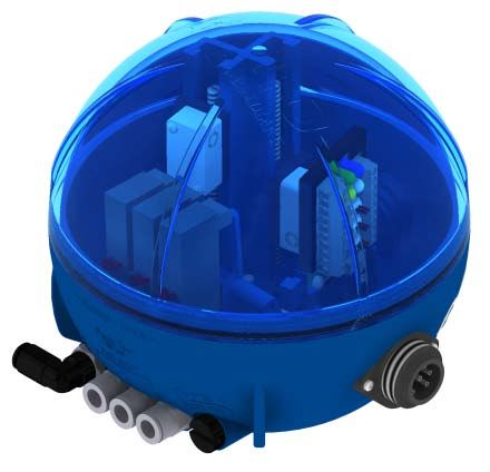
The Company BARDIANI VALVOLE reserves the right to modify its products at any time without prior notice. (GB-IST-GIOT-1113) 3/253. Structure and functions of Giotto Top®
The control unit is designed to control pneumatically-operated process valves. Giotto Top® can
be equipped with a maximum of three solenoid valves to control the process valve and up to a
maximum of three inductive sensors, the third one external, to control the position.
Position sensor
Solenoid valve LEDs terminal board
Vent valve
Pneumatic connections
Electrical connection
Anti-condensate membrane
AS-i card
There are three different configurations for the electrical connections inside the control unit:
• LEDs terminal board: The LEDs indicate the status of the valve, in presence of the respective
sensor: green light, valve open; yellow light, valve closed; white light, lower lift activated; blue
light, upper lift activated.
• AS-i card: the LEDs indicate the status of the corresponding solenoid valve.
The Company BARDIANI VALVOLE reserves the right to modify its products at any time without prior notice. (GB-IST-GIOT-1113) 4/254. Technical data
Number of solenoid valves
Number of solenoid
Type of application
valves
Single acting valves 1
Double acting valves (1 normally open and 1 nor-
mally closed), Mixproof and Twin-stop valves with 2
opening and upper lift
Mixproof valves with air supply for opening, upper
3
and lower lift
Electrical connections
7-pole connector or M12 5 or 8 pole.
Threaded union for cable gland PG11 or M20X1.5
Field bus connections
Actuator sensor interface (AS-i)
UL standards
Inside the control unit there are LOW VOLTAGE LIMITED ENERGY
CIRCUIT. Circuit protections must be sized accordingly to UL508A stan-
dard.
Class 2, 4, 3 pursuant
Air supply
to ISO 8573-1
Working temperature -10...+50°C
Always MAKE SURE the electrical and pneumatic connections are
NOT activated while working on Giotto Top® and that the power sup-
ply voltage is always and only 24 Vdc.
The Company BARDIANI VALVOLE reserves the right to modify its products at any time without prior notice. (GB-IST-GIOT-1113) 5/254. Technical data
Technical data of the control unit
from 0.55 kg to 0.65 kg in
Weight accordance with the
configuration
Shock proof PMMA
(methacrylate) and PA6-
Casing material
GF30 (Nylon reinforced
with fibreglass)
Gasket material NBR
Protection class IP67
Air inlet and discharge con-
1/8” (BSP)
nections
Air hose connections 6 mm / Ø6.35 (1/4”)
1mm amplitude,
Vibration
f=10..55Hz
Storage temperature -25..+70°C
Technical data of the solenoid valves
Electrical power supply 24 Vdc
max. 7bar
Air supply pressure
min. 6bar
Technical data of the Inductive sensor
Technical data of the Inductive sensor
Electrical power supply 24 Vdc
For further information concerning the component,
please consult the relevant manuals.
The Company BARDIANI VALVOLE reserves the right to modify its products at any time without prior notice. (GB-IST-GIOT-1113) 6/255. Installation
21b
25
22
114c
21a
2. To fit the cable gland (114c), remove the
1. Open Giotto Top® and make sure the gaskets are positio- enclosing disc of the cable gland sleeve using a
ned correctly (21a and 21b). Screw the two screws in place screwdriver and a mallet. Refer to the following
(25). Screw the cam (22). pages for the connection instructions.
3. Make sure the sensors are in the correct position,
otherwise adjust their height by means of the screws
on the double guide. 4. Connect the electrical and pneumatic supplies.
5. Always make sure all the wires are connected and tight in the terminals, that the solenoid valves, their sup-
port, the AS-i card and the LEDs terminal board (where installed) and other parts inside Giotto Top® are secured
firmly and assembled.
Always MAKE SURE the electrical and pneumatic connections are NOT
activated whilst working on Giotto Top® and that the power supply voltage
is always and only 24 Vdc.
The Company BARDIANI VALVOLE reserves the right to modify its products at any time without prior notice. (GB-IST-GIOT-1113) 7/256. Pneumatic connections
TYPE B
Compressed air inlet 1/8” (BSP) Connections for 1/8” air Air vent 1/8” (BSP)
fitting
TYPE S
Compressed air inlet 1/8” (BSP) Connections for 1/8” air Air vent 1/8” (BSP)
fitting
Use exclusively hoses with outside diameter of 6 mm.
Cut these hoses exclusively using a pipe cutting pliers to avoid damaging the ho-
ses, which could cause Giotto Top® to malfunction.
Select the appropriate length of the hoses so that Giotto Top® can be removed by
unscrewing the anchoring screws.
The Company BARDIANI VALVOLE reserves the right to modify its products at any time without prior notice. (GB-IST-GIOT-1113) 8/256. Pneumatic connections
Examples of pneumatic connections
S.E.N.C.: Valve with single B925: Valve open “AIR OUT 1”
D.E.: Valve with double acting
acting actuator (spring closes/ Upper seat flushing “AIR OUT 2”
actuator (air opens/air closes).
air opens). Lower seat flushing “AIT OUT 3”
ZVF, ZVS S.E.: Valve with sin- ZVF, ZVS D.E.: Valve with dou-
gle acting actuator ble acting actuator
The Company BARDIANI VALVOLE reserves the right to modify its products at any time without prior notice. (GB-IST-GIOT-1113) 9/257. Disassembling Giotto Top®
26
21b
22
25
21a
1. Disconnect the electrical and pneumatic sup- 2. Unscrew the cover (26), the cam (22) and the two
plies. screws (25). Remove the gaskets (21b and 21a).
TYPE B TYPE S AS-i
192d
283
21c 21c
3. Disconnect the inductive sensors and power supply cables from the LED board (21c). With AS-i card discon-
nect the solenoid valves board (192d), the sensors and the AS-i card. Be very careful not to do this with the
electrical power supply still connected.
The Company BARDIANI VALVOLE reserves the right to modify its products at any time without prior notice. (GB-IST-GIOT-1113) 10/257. Disassembling Giotto Top®
27d
27a
21d
4. Unscrew the double guide (21d), the inductive sensor block (27d) and the inductive (27a).
21c
21c
192
192 192b
192b
192e
192e
192c
192c
TYPE B TYPE S
192d
283
192
192b
192e
192c
AS-i
5. TYPE B; TYPE S
Remove the solenoid valve support (192b) making sure not to lose or damage the relevant seal rings (192e),
disassemble the solenoid valves (192) and the caps (192c) with the relevant gaskets, remove the terminal board
(21c) or the solenoid valve board (192d) and the AS-I card (283).
The Company BARDIANI VALVOLE reserves the right to modify its products at any time without prior notice. (GB-IST-GIOT-1113) 11/257. Disassembling Giotto Top®
114a 114c
21f 21g
21i
21e
6. Remove the air fittings (21e and 21g), the air caps (21i) and the air vent (21f). Unscrew the connector (114a)
or the cable gland sleeve (114c).
8. Assembling Giotto Top®
114a 114c
21f 21g
21i
21e
1. Fit the air fittings (21e and 21g), the air caps (21i) and the air vent (21f). Screw the electrical connection in
place (114a) or the cable gland sleeve (114c).
The Company BARDIANI VALVOLE reserves the right to modify its products at any time without prior notice. (GB-IST-GIOT-1113) 12/258. Assembling Giotto Top®
21c
21c
192
192 192b
192b
192e
192e
192c
192c
TYPE B TYPE S
192d
283
192
192b
192e
192c
AS-i
2. TYPE B; TYPE S
Fit the solenoid valves (192) being careful not to damage or lose the relevant gaskets. Fit the solenoid valve
support (192b) back in place with the board (192d), if present, and the seal rings of the support (192e). Insert the
terminal board (21c) or the AS-i card (283).
27d
27a
21d
3. Screw the double guide (21d), the inductive sensor block (27d) and any
inductive sensors (27a)
The Company BARDIANI VALVOLE reserves the right to modify its products at any time without prior notice. (GB-IST-GIOT-1113) 13/258. Assembly of Giotto-Top®
21c 21c
TYPE B TYPE S
4. Connect the inductive sensors, the power supply cables and the solenoid valves to the LEDs terminal board
(21c) or to the solenoid valve board. If present, connect the AS-I card to the solenoid valve board. Be very care-
ful not to do this when the electrical power supply is connected.
26
21b
22
25
21a
5. Insert the gaskets (21a and 21b). Screw the two
screws (25) to secure Giotto Top® to the cylinder and
screw the cam (22) in place. Screw the upper cover
on (26). 6. Connect the electrical and pneumatic supplies.
Always MAKE SURE the electrical and pneumatic connections are NOT
activated whilst working on Giotto Top® and that the power supply voltage
is always and only 24 Vdc.
The Company BARDIANI VALVOLE reserves the right to modify its products at any time without prior notice. (GB-IST-GIOT-1113) 14/259. Electrical connections The Company BARDIANI VALVOLE reserves the right to modify its products at any time without prior notice. (GB-IST-GIOT-1113) 15/25
8. Electrical Connections

The Company BARDIANI VALVOLE reserves the right to modify its products at any time without prior notice.   (GB-IST-GIOT-1113) 16/25
8. Electrical Connections

The Company BARDIANI VALVOLE reserves the right to modify its products at any time without prior notice.   (GB-IST-GIOT-1113) 17/25
10. Installing solenoid valves

Giotto Top® may have up to three solenoid valves and their number can be changed at any time.
To install additional solenoid valves use the following instruction.

                                                                                                              192b
                                                              192

                                                                                                              192e

                                                            192c

                                                             21g

  1. Remove the solenoid valve support (192b) from the base, remove the caps (192c) making sure not to damage or lose the
  relevant gaskets and seal rings of the support (192e) and remove the air connection plug (21g).

                                                                                                                   192
                                                                                                                     192
                        192                                                 192b                                                         192b
                          192

                                                                               192e
                                                                                                                                           192e

                  TYPE B                                                                                   TYPE S
                     21i                                                                                     21i

  2. TYPE B TYPE S
  Fit the additional solenoid valves (192) being careful not to damage or lose the relevant gaskets. Fit the solenoid valve
  support (192b) and the seal rings of the support (192e). Fit the air fitting (21i) and connect the additional solenoid valve to the
  LEDs terminal board.

The Company BARDIANI VALVOLE reserves the right to modify its products at any time without prior notice.                   (GB-IST-GIOT-1113) 18/25
10. Installing solenoid valves
Installing the external inductive sensor
2. Insert the cable gland (PG7 or M12x1.5) in the hole and block it
1. Drill Giotto Top® by the pre-arranged in place with the ring nut, insert the cable of the external inductive
imprint. sensor and block the pressure dome of the cable gland.
21c 21c
TYPE B TYPE S
4. TYPE B TYPE S
Connect the inductive sensor following the instructions from page 15.
4. Connect the external inductive sensor, inserting it in the dedicated slot in the assembling part and adjust the
vertical and horizontal position by means of the two adjustment screws.
Make sure the distance from the stem is less than 1.5 mm to ensure correct operation.
The Company BARDIANI VALVOLE reserves the right to modify its products at any time without prior notice. (GB-IST-GIOT-1113) 19/2511. Trouble shooting
PROBLEM POSSIBLE CAUSE POSSIBLE SOLUTION
Air leak from solenoid val-
ve support Gaskets missing or screws Check the seal of the ga-
Air leak from the safety not tight skets and tighten the screws
valve
Electrical board damaged
Replace the electric board
LEDs damaged
The LEDs do not switch
on Check the connections on
Electrical connections not the terminal board on the
connected correctly electrical board and tighten
the screw
Solenoid valve damaged Replace the solenoid valve
Electrical board damaged Replace the electrical board
Supply air pressure not Consult the Technical Data of
correct the manual
The solenoid valve does
not activate Solenoid valve support Replace the solenoid valve
damaged support
Check the connections on
Electrical connections not the terminal board on the
connected correctly electrical board and tighten
the screws
Inductive sensors or mi- Replace the inductive sen-
croswitches damaged sors or microswitches
Check the connections on
The inductive sensors of Electrical connections not the terminal board on the
the microswitches do not connected correctly electrical board and tighten
work the screws
Distance between the cam
Check if Giotto is centred
and the inductive sensor
and secure the double guide
more than 1.5 mm
ALWAYS MAKE SURE the electrical and pneumatic connections are
NOT live or pressurised while working on Giotto Top® and that the power
supply voltage is always and only 24 Vdc.
The Company BARDIANI VALVOLE reserves the right to modify its products at any time without prior notice. (GB-IST-GIOT-1113) 20/2512. Maintenance
MAINTENANCE
When used correctly, Giotto Top® does not need any maintenance in particular. Feasible
repairs shall be carried out exclusively by authorised personnel and making sure to DI-
SCONNECT the electrical power supply before starting any work inside Giotto Top®.
Before using any cleaning products, MAKE SURE they are compatible with the
constructional material of Giotto Top®, both its cover and its gaskets.
If solvents or cleaning agents containing acids or alkaline substances are used,
always make sure Giotto Top® is rinsed straight afterwards with clean water.
In doing so, be careful around zones where there are orifices or hollows.
During maintenance work or cleaning NEVER open the breather valve as this
could cause damage to the installation or personnel.
Every time the cover is opened make sure the various wires are re-positioned as
not to interfere with the movement of internal parts.
If any component of Giotto Top® should need replacing, contact Bardiani valvole
s.p.a. to purchase the spare part required, because the feasible use of a product
that is not supplied by our company could compromise correct operation and
could cause hazards for personnel.
The Company BARDIANI VALVOLE reserves the right to modify its products at any time without prior notice. (GB-IST-GIOT-1113) 21/2513. Part list The Company BARDIANI VALVOLE reserves the right to modify its products at any time without prior notice. (GB-IST-GIOT-1113) 22/25
13. Part list

The Company BARDIANI VALVOLE reserves the right to modify its products at any time without prior notice.   (GB-IST-GIOT-1113) 23/25
13. Parts List
                    POS.                          DESCRIPTION                                  POS.        DESCRIPTION

                       21         Base
                      21a         Seal ring
                      21b         Seal ring
                      21d         Double guide
                      21k         Terminal board + support
                       22         Cam
                       26         Cover
                      114         Cable with plug
                     114a         Male connector
                     114b         Female connector
                     114c         Sleeve for cable gland
                      192         Solenoid valve
                      283         AS-i cards

The Company BARDIANI VALVOLE reserves the right to modify its products at any time without prior notice.             (GB-IST-GIOT-1113) 24/25
Foreword This “Instruction, Use and Maintenance Manual” forms an integral part of the valve. Before proceeding with installation, use or maintenance of each type of valve it is compulsory to read and understand this manual. Keep this manual for future reference. When using valves which comply with ATEX Directive 94/9/EC (ATEX) it is compulsory to read the relative manual. This “Instruction, Use and Maintenance Manual” has been drawn up expressly for expert technical personnel. Consequently any information which can easily be deducted from reading the text and/or examining the illustrations and/or drawings provided herein shall not be the object of further explanation. It being understood that the essential characteristics of the valve type described herein shall remain the same, the manufacturer reserves the right to amend and/or integrate and/or update the data and/or information relative to use of the valve provided in the “Instruction, Use and Maintenance Manual”, at any time and without prior notice. The latest, updated version of the “Instruction, Use and Maintenance Manual” is always available at www.bardiani.com . The manufacturer shall not in any way be held liable for any consequences resulting from failure to observe all the prescriptions provided in the relative manual concerning installation, use, maintenance and care of the product. All rights are reserved. It is forbidden, without due written authorization from the manufacturer, to copy totally and/or partially and /or transfer and/or record any part of this “Instruction, Use and Maintenance Manual” using any means and/or support, including IT and/or electronic and/ or mechanical and/or paper form or any other means or system for recording and/or reusing the information contained herein for any purposes other than for the purchaser’s personal use. Warranty 1. VALIDITY Bardiani Valvole S.p.A. guarantees its own products against any design and/or construction and/or material defects and/or faults for a period of 12 (twelve) months from the date of delivery. Notification of any product defects and/or faults must be sent in writing to Bardiani Valvole S.p.A. within 8 (eight) days of coming to light, providing adequate documentation of the defect/fault encountered can be provided as evidence. Any repairs made during the warranty period do not extend said period over the stipulated 12 (twelve) months which remains definite. 2. CONTENTS OF THE WARRANTY This warranty it to be intended as limited, at the discretion of Bardiani Valvole S.p.A., to the repair and/or replacement of the product and/or part of the product and/or its components which is/are found to be defective due to design and/or manufacturing and/or material faults. In the event of repair and/or replacement of the product and/or any one of its parts and/or components, any returned item/s shall become the property of Bardiani Valvole S.p.A and the relative shipping costs shall be at the expense of Bardiani Valvole S.p.A. Bardiani Valvole S.p.A., shall be under no obligation to compensate for any immaterial and/or indirect damages and shall in no way be held liable for consequential damages and/or losses, such as (by way of example only), damages due to loss of business, contracts, opportunities, time, production, profits, goodwill, image etc.. No retailer or distributor or dealer or agent or representative or employee or person appointed by Bardini Valvole S.p.A. is authorized to make any amendments and/or integrations and/or extensions to this warranty. 3. EXCLUSIONS FROM THE WARRANTY All purchaser rights, as established and recognized by law being understood and unaffected, elastomers and electrical components are expressly excluded from this warranty. This warranty does not cover design faults whenever a product is built by Bardiani Valvole S.p.A. based on designs and/or technical specifications provided by the purchaser. This warranty also does not cover: - faults and/or defects resulting from incorrect and/or unsuitable and/or improper transport, - faults and/or defects resulting from installation of the product which fails to observe the indications provided in the “Instruction, Use and Maintenance Manual” or in any case caused by incorrect and/or unsuitable and/or improper installation, - faults and/or defects resulting from use and/or maintenance operations and/or storage of the products which fail to observe the prescriptions provided in the “Instruction, Use and Maintenance Manual” or in any case which are incorrect and/or unsuitable and/or improper, - faults and/or defects ascribable to normal wear and tear of the product and/or its parts and/or its components, - faults and/or defects in the product and/or its parts and/or its components whenever interventions and/or repairs have been performed by persons not authorized by Bardini Valvole S.p.A. and/or who are not suitably qualified, - faults and/or defects in the product and/or its parts and/or its components ascribable to it being dropped and/or banged and/or dented and/or misuse and/or tampering and/or breakage and/or accidents caused by negligence and/or lack of care by the purchaser and in general for any causes not ascribable to design and/or manufacturing and/or material defects, - faults and/or defects in the product and/or its parts and/or its components ascribable to negligence and/or carelessness and/or lack of care by the purchaser, - faults and/or defects in the product and/or its parts and/or its components caused by other events outside the control of Bardiani Valvole S.p.A. or determined by force majeure or mishap. Recommendations 1. All the information, indications, statements and technical details provided herein are based on test data which Bardiani Valvole S.p.A. holds to be reliable but which cannot be expected to cover every possible use of the product. 2. The illustrations and drawings provided are all indicative and are not binding, consequently they may not fully match the real appearance of the products. 3. Being as the conditions of product use and applications cannot be controlled by Bardiani Valvole S.p.A., the purchaser must ascertain suitability of the use he intends to make of the product beforehand and assume all risks and liabilities which may result from the same. 4. Customers are strongly advised to consult Bardiani Valvole S.p.A.’s technical-commercial collaborators to request any specific information concerning the technical characteristics of the products. 5. The information provided in this document refers to standard production Bardiani Valvole S.p.A. products and therefore cannot be considered a basic reference for products built to meet specific requirements. BARDIANI VALVOLE S.P.A. - Via G. di Vittorio 50/52 43045 - FORNOVO TARO - PR - Tel.: +390525/400044 - Fax.: +390525/3408
You can also read