Chilled ceiling system - Type WK-DK-S L-11-4-07e
←
→
Page content transcription
If your browser does not render page correctly, please read the page content below
L-11-4-07e

Chilled ceiling system
Type WK-DK-S
Thermally activated chilled ceiling panels
Content · Description
Content
Description ____________________________________ 2
Dimensions · Design ___________________________ 3
Ambient air · Design · Technical data _____________ 4
Functions · Performance ________________________ 5
Perforation · Sound absorption __________________ 6
Lighting _______________________________________ 7
Order Details __________________________________ 8
Description
A pleasant indoor climate with a high level of comfort Modular design
Everyone has a varying level of sensitivity and different TROX HESCO Schweiz AG has created a high-quality chilled
expectations with regard to temperature and ventilation in ceiling panel, which can be expanded in the simplest way to
the workplace. Therefore, one person may find it too warm, include lighting, ventilation and thermo-active concrete con-
another too cold and yet others may complain of draughts or nections.
too high a noise level. The comfort of a room is determined The WK-DK-S chilled ceiling panel brings together the indi-
by ambient temperature, moisture in the air, speed of flow vidual requirements of a room – cooling, heating, aesthetics,
and architectural factors such as lighting and colouring. acoustics, lighting and fresh air supply – into a single prod-
uct.
External effects, such as daytime temperature and solar
radiation, as well as indoor factors, for example people, Functional principle
computers, machines and lighting, have an influence upon From a technical perspective, a cooling panel is a large heat
the thermal indoor climate. The atmospheric environment is exchanger fitted beneath the main ceiling. The cooled water
seldom consciously perceived. A deviation of the relevant flows through the copper pipe meander with a supply flow
parameters beyond the comfort range leads to unpleasant temperature of approximately 16°C. The entire ceiling sur-
conditions. This in turn may have an effect upon perfor- face is cooled via the heat conducting rails made of alumin-
mance, the onset of illness or an increased risk of accidents. ium, which cover the copper pipe meander. All heat sources
Chilled ceiling technology counters these negative factors in in the room now give their excess heat energy to the cooled
an intelligent way. ceiling area via radiation exchange and convection.
Thermally activated chilled ceiling panels
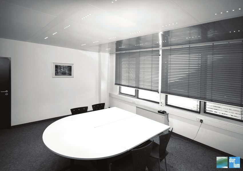
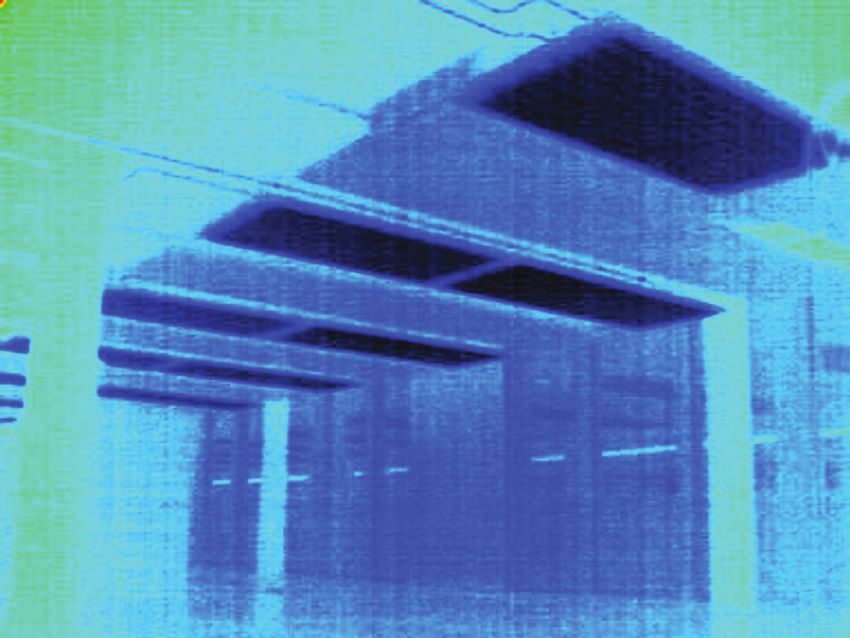
Cooling ceiling panels in an office building Thermographic image
2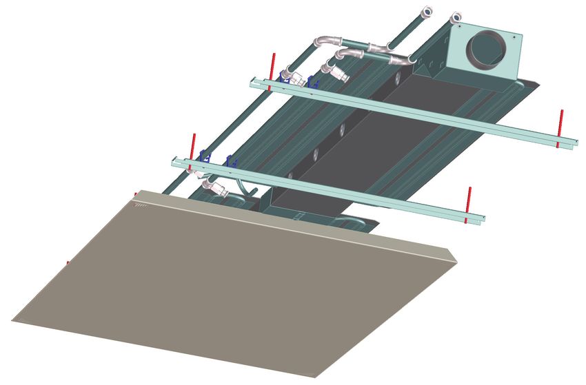
Dimensions · Design

Dimensions and design of cooling ceiling panels                                                  Single element: maximum length 3.00m
The chilled ceiling panel is produced to a maximum length of
2.25m and can be connected to form a multi-part panel.

Maximum dimensions for multi-part ceiling panels: 6.75 m

Chilled ceiling panels are supplied as standard in three
widths and two different outer edges of 90° and 55°.

           20                                                           15        29.7   14                                 12             29.7

                =                                                   =
50

                                                                             45

                                                                                                                            55°
                                                                                    55
                                                                                     °

                            Width: 800/1000/1200 mm                                               Width: 800/1000/1200 mm

Design variants                                                              Passive chilled ceiling panel
The chilled ceiling panels can be designed with or without air
or concrete activation as required.                                                                                              min. 109 mm

                                                                                          600/800/1000/1200 mm

Active chilled ceiling panel with                                            Active chilled ceiling panel with
200mm supply air duct                                                        400mm air supply duct
                                                                                                                                 min. 109 mm
                                                      min. 109 mm

                       200 mm                                                                     400 mm

                600/800/1000/1200 mm                                                          800/1000/1200 mm

Active chilled ceiling panel with 200mm                                      Active chilled ceiling panel with 400mm
supply air duct and concrete activation                                      supply air duct and concrete activation
                                                                                                                                 109 mm
                                                      109 mm

                       200 mm                                                                     400 mm

                    800/1000/1200 mm                                                            1000/1200 mm

                                                                                                                                                  3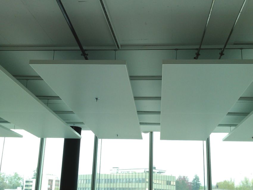
Ambient air · Design · Technical data
Ambient air                                                        Design

TROX HESCO supply air modules for optimum delivery of              The TROX HESCO supply air module has been specially de-
prepared air indoors according to the mixed air principle. An      veloped for optimum air intake of prepared air in association
even flow profile is ensured through built-in special jets with    with a thermally activated chilled ceiling panel.
shaped blades.                                                     It has the best ventilation efficiency, i.e. the lowest possible
                                                                   pollutant load as well as optimum thermal comfort in the
To achieve optimum ventilation, the supply air must be             workplace or living area.
brought in at a lower temperature than the room.                   The supply air channel is made as standard from galvanised
Ideally, the temperature difference between the supply air and     steel sheet and is maintenance-free, as no filter material is
exhaust air will be -2 to -6 K.                                    used.
                                                                   The geometrically arranged siphoning jets with shaped
                                                                   blades, X30, made of PP plastic, siphon off an equal partial
Advantages:                                                        volume flow per jet and guide these evenly to the side via the
- Thanks to the integrated supply air channels, the fresh air is   ceiling panels.
  optimally distributed in the room without causing draughts.      The supply air module also has specially arranged undulating
- Due to increased convection via the ceiling panel, the           air passage apertures, which support the discharge of the
  cooling capacity can also be raised.                             thermal mass.
- The module is very simple to install due to channel
  connections that are designed to be plugged in.
                                                                   Technical data
                                                                   In the standard design, the supply air module is delivered as
                                                                   a ready-to-install unit with an air duct connection, as well as
                                                                   1 or 2 connection nozzles (with seal) of Ø80 mm or Ø100 mm
                                                                   for a spiral duct or hose mounting.

                                                                   Detail of air connection

                                                                   Detail of air supply duct with concrete activation

Volume flow per panel
                                                                     Pipe entry speed
                                          1.5 m/s            2.0 m/s      2.5 m/s     3.0 m/s                      3.5 m/s
    Air supply         Pipe-Ø
    module
     Width [mm]           [mm]         m3/h       l/s     m3/h     l/s     m3/h       l/s     m3/h       l/s     m3/h       l/s
             200             80         26        7.2       34      9.4       43     11.9       52      14.4       60      16.7
             200            100         41      11.4        54     15.0       68     18.9       82      22.8       95      26.4
             400          2x80          52      14.4        69     19.2       86     29.1      103      28.6     120       33.3
             400        2x100           82      22.8      109      30.3     136      37.8      163      45.3     190       52.8
                                                                          Ideal range
4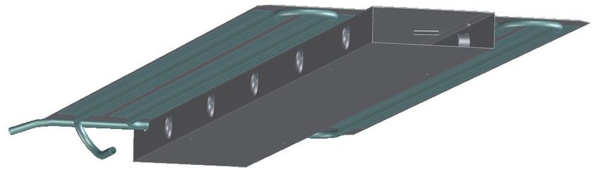
Functions · Performance
Functions
Cooling supply air is brought into the room by a row of plastic sipho-
For cooling, the energy saved in the concrete is used first. ning jets above the cooling module on both sides. Above it,
If this is no longer sufficient, then the active cooling ceiling against the ceiling are additional air outlet apertures, which
plates will be switched on. The various daily peaks can then ensure optimum heat exchange and better heat transfer to the
be dissipated. concrete ceiling. This enables efficient usage of the con-
crete. The air goes through a special connection box into the
Heating module.
For heating, warm water is fed through the module in place
of cold water. In this case, only the lower circulation (ceiling Sound absorption
plate circulation) is used. The exchange with the room is The ceiling plates are fitted with acoustic fleece as standard.
carried out via the warm radiant surface. The component Based on insulation requirements, additional acoustic mats
activation is thereby uncoupled and does not heat up the can also be laid in the plates. The module can then be indivi-
concrete unnecessarily. dually equipped based on requirements.
Concrete activation Lighting
The performance capacity of the concrete mass is usually Various types of lighting can be built into the module. Strip
specified using 10-20 W/m2. However, this volume cannot lights, spots or LED lights can be used. For each type of
be taken directly from the overall capacity required. Loading installation the module heights are specific to the lighting.
and unloading of the concrete ceiling is time-delayed in terms
of the heat loads and has to be considered across a whole Aesthetics
24 h of the energy requirements. The structure itself is also The use of different perforations and colours ensures a wide
taken into account in the energy management of the build- spectrum in the design of the module. The shaping (right-an-
ing. The load removal is carried out via the whole day / night gled 90° or angled 55°) of the plates can be used as required.
cycle. Throughout the day the heat quantity developing is
only partly discharged, and the rest is stored in the concrete Additional parts
ceiling. At night this heat quantity is withdrawn from the con- The integration of complementary parts, such as fire alarms,
crete once again so that the “concrete storage” can optimally sprinklers, warning devices, etc. can be carried out specifical-
gather the heat produced for the next day. ly for the project.
Ventilation
The integrated air channel serves as a primary air input as
well as a hanging bracket for the cooling ceiling plates. The
Functional drawing of a chilled ceiling panel with concrete activation
E E
C = convection
E E R = radiation
R primary air
R E = energy flow
R R
primary air primary air
C C
R R R
C C C C
Temperatur-
Example of a dynamic und Lastverlauf
load calculation
35
Temperatur- und Lastverlauf 90 - Variable room temperature
33 80
- Load peaks are covered by stored energy
35 90
31
- Maximum load dissipation up to 80 W/m2 BF
70
33 80 - Constant water inflow
29
60
W/m2BF W/m2BF
- Capacity via the amount of energy over the
Temperature °C
31 27 70
50 course of the day
Load distribution
29 25 W/m2 BF
Load distribution
60
40
Temperature °C
27 23 External temp.
50
30 Load distribution
21
25 W/m2
Room BF
temperature
Load distribution
20
19 40
23 External temp.
17 10
Total hourly head load 30
21 15 0
1 2 3 4 5 6 7 8 9 10 11 12 13 14 15 16 17 18 19 20 21 22 23 24
Room temperature
20
19
17 10
5
15 0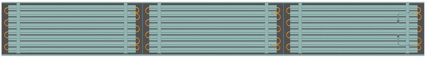
Perforation · Sound absorption

  Perforation

    Besides the standard perforation, there is a selection of other
    perforations. Request our perforation range brochure.

    RG-L15                                                                                      RD-L30

    Hole diameter               2.5 mm                                                          Hole diameter               1.5 mm
    Free profile                 16.2%                                                          Free profile                   22%
    Maximum perforation width 1397 mm                                                           Maximum perforation width 1250 mm
    Maximum panel width       1400 mm                                                           Maximum panel width       1400 mm

  Sound absorption

  The long-lasting acoustic fleece bonded into the cooling pa-
  nel has a positive effect on the acoustics of the room.
  Absorption is also independent of the selected perforation
  and the height of the ceiling hollow space.

  Sound absorption values of Durlum panel with fleece
  L30, 1.5-2.38-22%
  Degrees of absorption
                                     Without activation          70% activation

                       1.20
                       1.10
                       1.00
Degree of absorption

                       0.90
                       0.80
                       0.70
                       0.60
                       0.50
                       0.40
                       0.30
                       0.20
                       0.10
                       0.00
                              125   250               500           1000          2000   4000
                                                Frequency [Hz]

    6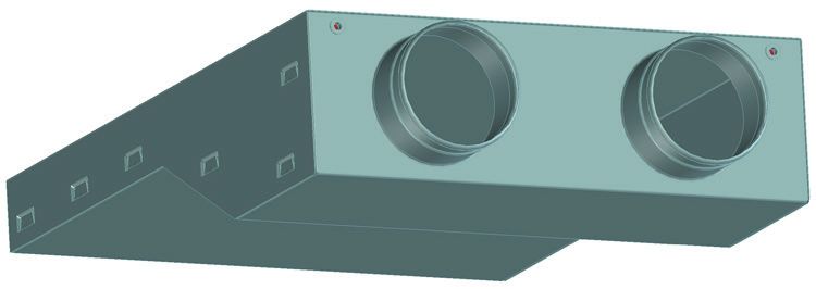
Lighting

Lighting (optional)                                   LED point lights integrated into the ceiling
                                                      PUNTEO®-N are LED point lights, which can be individually
                                                      adapted to the room design. With an efficiency level of more
                                                      than 80%, PUNTEO®-N fulfil all the requirements of an eco-
                                                      logical lighting system.

                                                      PUNTEO®-N can be integrated optimally into the durlum
                                                      ceiling systems. Thanks to the LED-based PUNTEO®-N
                                                      technology, no lights can be seen but only small 8mm aper-
                                                      tures in the frames or plates of the metal ceiling, through
                                                      which the light shines. The light flux of the LED is directed
                                                      through the small opening in the metal ceiling plate via a
                      Variant 1x5                     lens system.

                                                      Advantages:
                                                      - Extensive lighting through cross-over radiation
                      Variant with long hole:
                      adjustable radiator, e.g. for
                                                      - Can be evenly distributed across the room
Variant 5x5                                           - Independent workplace organisation
                      wall lighting
                                                      - Heat is not radiated in the room itself but in the space
                                                        above the ceiling

                                                              PUNTEO®-N 1x1           500 1000    cd/klm

                                                      We will be pleased to support you, from the initial idea to the
                                                      commissioning of your system.

                                                                                                                      7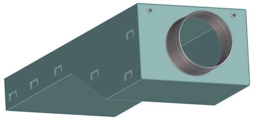
Order Details

Order codes
                                     No information for basic designs

      WK-DK      -   S   -   A   -   0   -   0   -   0   -   90   /   B×L   -   n x d x ...   /     0   /    0    /   RAL... , ..%

Typ
WK-DK = water-cooled
                                                                                                            RAL 9010 matt,
		 ceiling panel
                                                                                                            Approx. 25% gloss level

S = Steel ceiling plate                                                                       0  = Powder-coated RAL 9016 matt,
		(standard)                                                                                       according to 25% gloss level
                                                                                                   (standard)
                                                                                              P1 = Powder-coated RAL...
A     = activated (standard)                                                                       (more RAL colours and gloss
I     = inactive                                                                                   levels upon request)

0 = without concrete                                                                          0      = RG-L15 ceiling panels
		 activation (standard)                                                                               perforation (standard)
B = with concrete activation                                                                  RD-L30 = RD-L30
                                                                                                       More upon request
0 = without air channel (standard)
		 (not possible with concrete activation)                                                    0     = without connection nozzles
K = with air channel                                                                          n x d = No. nozzles x
                                                                                                      nozzle diameter x
                                                                                                      channel width
                                                                                                      1 x 80 x 200 mm
0     = without lights (standard)                                                                     2 x 80 x 400 mm
L     = with lights                                                                                   1 x 100 x 200 mm
                                                                                                      1 x 100 x 400 mm
                                                                                                      2 x 100 x 400 mm

                                                                                                  B x L = Width x total length
                                                                                                                                     We reserve the right to make design and shade of colour changes (02/2015)

                                                                                                  90    = 90° bend (standard)
                                                                                                  55    = 55° bend

Order examples
15 units   WK-DK-S-A-B-K-55 / 1200x1000 - 2x80x400 / P1 / RAL9010, 25%
20 units   WK-DK-S-A-55 / 1200x1000

8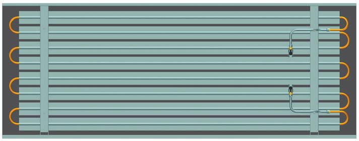
You can also read