Developers Guide Working Standards, Groundworks, Installation and Metering - Energy Assets
←
→
Page content transcription
If your browser does not render page correctly, please read the page content below
Developers Guide Working Standards, Groundworks, Installation and Metering
2                                                                          3

Our Guidelines
                                                               Emergency
                                                               Numbers
We have put these
guidelines together to                 Our Core
give our customers
clear information about                Values
Working Standards,
Groundworks, Multi
Utility installation and
Metering.
Please read these guidelines to
make sure you understand what

                                                  Electricity
is required before any Utility works
commence.

We are striving to offer our
customers Platinum Customer                       Telephone:
Service and any feedback from
you on how we can improve
the service, communication
                                                  0333 800 2016
and information we currently
offer, would be appreciated
and acted upon.

                                                  Gas
                                                  Telephone:

                                                  0800 111 999
4 5
Developers Responsibilities Essential Requirements
At a Glance
Marker tape indicating ‘Gas Main Below’
must be installed a minimum of 150mm
above the crown of the gas pipe.
Trenches must be backfilled with fine fill. Mechanical
compaction equipment must not be used within
200mm of the crown of the gas service pipe. Layers of
• Notify EAU of any contaminated land, site • For gas mains the trench must be excavated to a backfill material must be hand rammed until the depth
located in flood plain or subsidence concerns depth of 750mm + the diameter of the pipe in carriage of cover is achieved.
way/verge and 600mm + the diameter of the pipe in
• Let EAU know of any variation that might have an footpath
impact on the design due to layout changes such as
moving, adding, or deleting properties or any changes • The service trench must be excavated to a depth of
to the types of properties being constructed 600mm + pipe diameter (for the last 2 metres) at the
property end and must be between 200–300mm wide
• Provide safe, secure areas for storage to fit 32mm black bends
of materials
• Appoint shipper/supplier
• Ensure other utility plant is installed correctly In accordance with the Pipeline Safety Regulations, the services
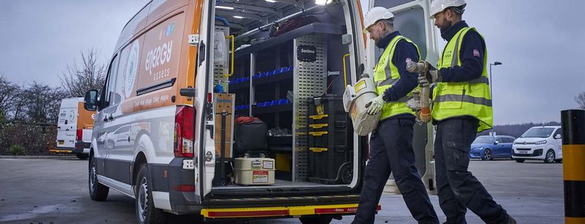
as per NJUG requirements to avoid • All wall piercings must be sealed to the relevant should be perpendicular to the property and then take shortest
standard or any cavity in the wall and space around route possible to the gas main. Services should be laid at a
• The pipe route should avoid drains, manhole covers the outlet spigot /sleeve pipe to be sealed with fire depth of 450mm, dropping to a depth of 600mm (for the last 2
and other obstructions resistant compound to prevent gas escaping into the metres at the service termination.
premises
• The route must not be excavated inside premises or
underneath any building, including garages, sheds, • The backfill and reinstatement requirements include
porches and conservatories etc restoration of the trench and any associated surfaces.
During the backfill process “Gas Pipe Below” warning
• EAU will install the main in a pre-excavated tape must be installed a minimum of 150mm above
trench that must be available prior to attendance on the crown of the gas mains and service pipe
site if you are down to dig. Any unplanned additional
visits required to install the main will be subject to • Shear bolts from the meter bracket must be kept in
additional charges where part day working is required place and must not be removed by a third party or Trenches must have a soft trench bed, must be free from
damaged due to soldering bricks, rubble sharp stones, etc. For gas mains the trench
• Outer limits of footpaths must be defined and finished must be excavated to a depth of 750mm + the diameter of
levels indicated • The developer must ensure that Ground Workers the pipe in carriage way/verge and 600mm + the diameter
receive a copy of this guide and are properly of the pipe in footpath. Exposed gas pipes should not be
• Remove scaffolding that will affect the works instructed. commissioned. All mains need to be sanded prior to pressure
that have been booked in testing and this should be done as soon as we request it so
that it does not cause delays.
6                                                                                                                                                                                       7

Permeable Surfaces                                           Gas Meters and Boxes

                                                                            Gas Meter Box                                                  Gas Meter
                                                                            Installations                                                  Installations

                                                             • It is a legal requirement that only competent people            The completed installation pipework should be
                                                               shall carry out any work in relation to gas fittings.           suitably protected and must be soundness tested in
                                                               Employers have a responsibility to ensure that all              accordance with BS6891
                                                               employees undertaking work on any gas fitting are
                                                               competent                                                      • The emergency control valve will be sited no higher
                                                                                                                                than 1.8 metres from floor level
                                                             • Gas sleeves and boxes must be a minimum
                                                               of 150mm away from any air bricks                              • On installation of the meter a sealing disc will be
                                                                                                                                placed in the outlet union of the meter, the meter
                                                             • When delivered to site the meter box becomes the                 installation soundness tested, purged and the
                                                               responsibility of the Developer. On delivery they                installation left ready for the final outlet connection.
                                                               should be inspected for transit damage a damaged                 Installation purging and commissioning is to be carried
                                                               box must not be used. Any defective boxes should be              out by the Developer’s Gas Safe Registered Installer
Some developments incorporate                                  reported immediately to EAU, who will arrange for a
                                                               replacement                                                    • When carrying out the final connection the meter
permeable surfaces to allow the infiltration                                                                                    MUST be removed before any soldering takes place.
of surface water through the surface.                        • During the brick washing process around meter boxes,             The end of the outlet pipe should then be cut back
If your development contains areas of                          please ensure meter boxes are covered as the acid                to suit the final connection. Care must also be taken
land where permeable surfaces are being                        can damage meter anacondas. This could delay your                when using a blowtorch near the meter box
                                                               works and you will be charged for repairs if it occurs.
constructed, EAU should be notified as
soon as possible.                                            • Meter boxes that are replaced due to on site damage
                                                               and any associated works required to replace the box
It is recommended that new gas infrastructure should           will be charged to the Developer
not be installed within these areas as the water retaining
surface/membrane could become compromised if the             • Each meter box will be supplied with a key that must
highway has to be excavated in the future to access the        be passed onto the householder. There are typically
main for repair and/or maintenance.                            three types of meter boxes available for use with new
                                                               properties, they are: – i) Uni-box ii) Built-in iii) Surface
Early identification and notification is extremely             mounted
important as it allows both the developer and EAU at
an early stage of the process of design to determine         • On some sites there may be a requirement for
the most optimum solution of overcoming the difficulties       gas infrastructures termed as ‘Medium Pressure
associated with supplying properties that front highways       Installations’, this will be clearly marked on the
with permeable surfaces.                                       construction drawing. These types of installations
                                                               operate at a higher-pressure tier than the more
This can sometimes involve specifying designated               common Low Pressure infrastructures. Only the
service strips/easements and/or additional technical           Uni-Box can be fitted on these sites. In a situation
considerations for the safe installation of gas apparatus.     where the development is a refurbishment project,
                                                               surface-mounted boxes can be used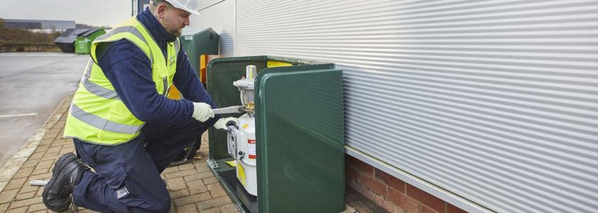
8                                                                                                                                                                                                  9

Universal Meter Box

All meters, where possible should be                        • This type of meter box may be partially buried up to
installed in meter boxes and be easily                        an absolute maximum of the base of the box being
                                                              75mm below ground from the finished ground level.
accessible to allow them to be maintained                     (Evidence of the height/position of the box will be
and the supply isolated when necessary.                       required after private/final reinstatement has been
                                                              completed). Any subsequent remedial works that may
It is the developer’s responsibility to identify and          be required to re-locate the meter box and associated
show the required meter positions on the site plans           infrastructure would be solely the responsibility of the
all in accordance with current meter location guidelines.     developer. Remedial works carried out by our service
Meter boxes to be fitted by the Developer, unless             provider will be chargeable
agreed with the Service Provider. All meter boxes
should be installed in accordance to the
manufacturer’s instructions.                                IMPORTANT NOTE                                                                   Fixing Instructions
                                                            Where Uni-boxes are to be partly buried at the foot of the house wall
The Uni-box has been designed as a relatively               they should only be located in areas that will be designated as flower
                                                                                                                                             1. Using the box as a template, mark the four
                                                            beds, an area of lawn or a border adjacent to a footpath of sufficient
unobtrusive installation partly buried at the foot of the   depth to ensure that the meter box does not impinge on the footpath.                fixing holes
house wall but protruding above ground level at the         If you choose not to comply with this instruction, then any alternative
wall. The depth of the box from the wall is 290mm. It       Developer meter locations that are considered to cause a trip hazard/            2. Drill the fixing holes and secure the box to the
houses the meter and the emergency control valve;           obstruction in the opinion of EAU, particularly when located on a                   wall using the plugs and screws provided
                                                            footpath, will be treated as unauthorised and the Developer will have to
access is via the hinged lockable lid.                      take full responsibility for any resulting trips, falls, incidents or injuries
                                                            that may occur and in addition to any subsequent required remedial               3. Fit the lid by passing the pins through the lid
• The Uni-box if so, required can be fitted as a            works that may be required to re-locate the meter box and associated                into the box and tap into position
  wall mounted surface box at a similar height              infrastructure.
  to a Built-in box                                         Before uni-boxes are installed careful consideration should be given
                                                                                                                                             4. The installation pipework should leave the
                                                            by the Developer to determine if the selected fixing position constitutes           box via the side or bottom knockouts
• The Uni-box must be located at the front of the and       a trip hazard/obstruction. The Developer will be asked to confirm if
  not on gable ends or at the rear of the dwelling          they still intend to locate uni-boxes in footpaths when accepting their          5. The installation pipe should enter the premises
                                                            quotation and, where this is the case, the Developer will be asked to
                                                                                                                                                as close as practical to the outlet of the
                                                            confirm in writing that they accept full liability for any future claims for
• The Uni-box must be positioned at least 150mm             trips or obstructions that the location of the box may have caused and              meter box, keeping the external pipework to a
  away from airbricks                                       subsequently any required remedial works that may be required to                    minimum. If at all possible, avoid running any
                                                            relocate the meter box to an alternative location.                                  pipework behind the box. The pipework entering
• Electricity service cables must not be installed                                                                                              the premises must pass through the wall using
                                                            In areas where the Developer predicts a trip hazard/obstruction, or is
  directly behind the meter box                             in any doubt of its safety, a Built-in meter box should be considered               a full-length sleeve. The annular space must
                                                            instead. In the majority of installations an earth bonding clamp should be          be sealed between the pipe and the sleeve with
• Please ensure that the finished position of the box is    evident as close as possible to the consumer’s side of the gas meter.               non-setting (mastic type) compound
  not a trip hazard/obstruction or exposed to damage
                                                            The clamp should also be connected to an earth bonding conductor
  from vehicles                                             which is subsequently connected to the consumer’s main earth terminal            6. The security of the installation is the
                                                            provided by the DNO. If the Universal box is to be partially submerged              responsibility of the owner/tenant therefore
• Reference should be made to the IMPORTANT                 the base of the box should be no more than 75mm below the finished                  please makes sure that the compartment door
  NOTE (below) with regards to meter positions that         ground level - an indication of this in a conventional build house, (i.e.           is secure, kept in the closed position and locked.
                                                            DPC 150mm above ground level,) 3 bricks below DPC/2 bricks below
  would constitute a trip hazard/obstruction in the
                                                            the air brick row
  opinion of EAU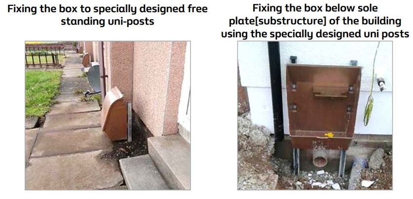
10                                                                                                                                                                                                                                                      11

Built-in/Recessed meter box

All meters where possible should be
installed in meter boxes and be easily
accessible to allow them to be maintained
and the supply isolated when necessary.
The Built-in / Recessed box is similar in
appearance to those provided by other
utilities.

• It is the developer’s responsibility to identify and
  show the required meter positions on the site
  plans all in accordance with current meter location
  guidelines. Meter boxes are to be fitted by the
  Developer, unless otherwise agreed with the Service
  Provider. All meter boxes should be installed in
  accordance to the manufacturer’s instructions

• The recessed gas meter box houses all domestic
  U6 and G4 meters and is designed to mirror the
  standard recessed electricity box. These boxes have
  been designed for insertion into the external leaf of
  a cavity wall and are suitable for conventionally built,   Fixing Instructions                                     6. Whilst building the box into the wall, it is
                                                                                                                        important that the sides are well bedded into
                                                                                                                                                                             Please note: Box dimensions may vary slightly from the manufac-
                                                                                                                                                                             turer’s information - please cross check installation dimensions with
  or timber frame dwellings                                                                                                                                                  those supplied with each meter box. In certain extreme circumstances,
                                                             1. The Developer prior to the service pipe                 the wall and that the outer edging architraves       it may be necessary to install the boxes into ready made openings.
                                                                being commissioned/connected installs the               are in close contact to the wall                     To facilitate a secure gas tight fixing, utilising a ‘Spit Hit’, Lightweight,
• Please ensure that where the outlet spigot/sleeve                                                                                                                          Hammer Set Anchor or similar. The following procedures should be
  at the back of the box is used to connect the                 boxes. THIS MUST BE DONE BEFORE WE                                                                           adhered to:– The cut out dimensions are 532mm high x 366mm wide
                                                                ATTEND SITE. The base of the box should be           7. The inner leaf should be built around the add
  installation/outlet pipework that the annulus between                                                                                                                      approximately, with a minimum depth between the outer face of the
                                                                located between 500mm and 1000mm above                  on extension spigot, ensuring that the space         inner leaf and the outside face of the outer leaf wall faces of 160mm.
  the pipework and the outlet spigot/sleeve is sealed
                                                                the finished ground level and above the D.P.C           between the sleeve and the wall is fully filled      After locating the box into the preformed opening, ensure the archi-
  with a flexible fire resistant compound to prevent gas
                                                                                                                        with mortar                                          trave is flush with the outer brick. If the box is to be fitted in this way, it
  ingress as shown in the above photograph.                                                                                                                                  must be fixed in place with a non corrosive adhesive.
  THIS MUST BE DONE BEFORE EAU CAN                           2. The meter box must be inspected for signs
                                                                of damage when delivery is made to site. Our         8. The outlet pipework can leave the box via the        Note: It must be emphasised that this is not the preferred method of
  CONNECT THE SERVICE AND METER.                                                                                        add-on sleeve at the back or via the lower right
                                                                personnel will not be permitted to install a gas                                                             installing recess type meter boxes and should only be undertaken
                                                                service pipe into a meter box that is damaged           hand front outlet. The spigot supplied will pass     when boxes are unavailable at the time of construction. An external
                                                                                                                        completely through walls up to 278mm thick           spigot on the rear of the box allows the outlet pipework to pass from
                                                                or insecure                                                                                                  the box into the building. The annular space between this pipework
                                                                                                                        and can easily be trimmed to length during           and the spigot must be sealed with a non-setting (mastic type)
                                                             3. The meter box to be positioned at the front of the      installation of the internal pipe work. The sleeve   compound. This is required to prevent any potential future leakage of
                                                                plot or no more than 2 metres from the gable end        must fully bridge the cavity                         gas entering the building. Where not already fitted, the spigot can be
                                                                                                                                                                             attached to the box using the three screws provided. Note: Failure to
                                                                down the side of the plot                                                                                    do this may result in a breach of the Gas Safety (Installation and Use)
                                                                                                                     9. Under no circumstances must any other holes
                                                                                                                                                                             Regulations 1998/ gas meter box installations.
                                                             4. For a secure installation, the box should               be made in the box for gas pipework or electrical
                                                                be built into the outer leaf as the building            cross-bonding cables. The box must be situated
                                                                progresses. Nails or spikes must not, under any         where it will not cause an obstruction or be
                                                                circumstances, be used to secure the box                exposed to damage from vehicles etc.

                                                             5. When the required height of brickwork is             10. Please ensure that where the outlet pipework
                                                                reached the box should be mounted onto a good            enters the property through the spigot/sleeve
                                                                mortar base. It is recommended that a polythene          at the back of the box that the annulus between
                                                                sheet be fitted as a damp-proof course above             the pipework and the outlet spigot/sleeve is
                                                                and behind the box                                       sealed with a flexible fire-resistant compound to
                                                                                                                         prevent gas ingress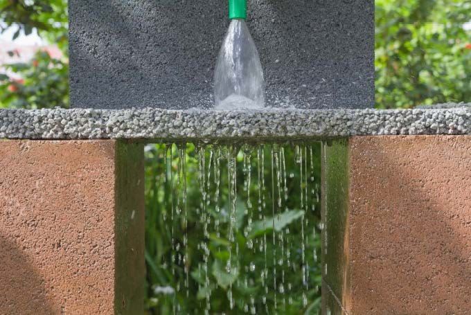
12                                                                                                                                                                                                                                          13

Surface Mounted Meter Boxes                                                                                             Non-Traditional Build
                                                                                                                        (Modular Construction/Cladding Dwellings)

                                                                                                                        • Non - traditional methods of construction, such as
                                                                                                                          modular construction methods are becoming very
                                                                                                                          popular in the UK construction industry. Specific
                                                                                                                          safety measures need to be carefully considered
                                                                                                                          before gas services are designed and installed
                                                                                                                          in non-traditional buildings. The Gas Installations
                                                                                                                          in timber framed and light steel framed buildings
                                                                                                                          procedures [IGEM/UP/7] states that meter boxes
                                                                                                                          shall not be inset into a structural timber panel

                                                                                                                        • Where a cladding of thickness less than 100mm of
                                                                                                                          masonry is used, EAU will not accept the installation
                                                                                                                          of any type of meter box installed within or directly on
                                                                                                                          to the structure of the building. Note: If the cladding    Fixing the box to specially designed free
                                                                                                                          is installed/affixed directly onto a traditional brick/    standing uni-posts
                                                                                                                          block internal skin wall, the use of a surface mounted
                                                                                                                          meter box (see Traditional Build – page 7) may be
                                                                                                                          acceptable, please consult with EAU before any
All meters where possible should be installed in meter boxes and                                                          works commence on site
be easily accessible to allow them to be maintained and the supply
isolated when necessary. It is the developer’s responsibility to                                                        • Alternative methods of supplying the dwelling can
identify and show the required meter positions on the site plans                                                          be offered by remotely installing the meter box away
                                                                                                                          from the structure.
all in accordance with current meter location guidelines. Meter
boxes to be fitted by the Developer unless otherwise agreed                                                             • Important: EAU advise to discuss the options
with the Service Provider. All meter boxes should be installed in                                                         available to you before any construction work begins
accordance to the manufacturer’s instructions.                                                                            where non-traditional methods of construction are
                                                                                                                          being used on your development

                                                                                                                                                                                     Fixing the box below sole plate (substructure) of
• This type of box is generally fitted to existing houses   • The box must be positioned at least 150mm away                                                                         the building using the specially designed uni posts
  undergoing conversion, older homes or where the             from airbricks
  Developer has specifically requested that they are to
  be utilized                                               • Electricity service cables or electric ducting must not
                                                              be installed directly behind the meter box
• The surface mounted meter box must be sited on the
  outer wall and the base should be 500mm from the            The lid of the box should be removed for fixing. The
  finished ground level and no more than 1500mm high          box should be positioned against the wall, levelled and
                                                              the four fixing holes marked and drilled. The box can
• The Box must be located at the front of the plot            then be fixed to the wall using suitable screws and
                                                              wall plugs. The lid should then be re-fixed and secured
• The box must not bridge the damp proof course               with bolts provided
  (D.P.C.), unless wall spacers have been installed
                                                            • The box should be fitted prior to EAU arriving on site
• The box should be positioned so that it is not exposed      to connect the gas service to the box
  to potential damage by vehicles or is a hazard to
  pedestrians. The box must not obstruct pedestrian         • Please ensure that the finished position of the box
  access or onto a driveway                                   is not an obstruction or exposed to damage from                                                                        Fixing the box to a nearby/designated dwarf wall or
                                                              vehicles.                                                                                                              similar structure capable of receiving the meter box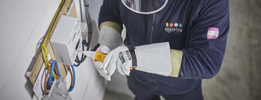
14                                                                                              15

Meter Locations &                                Non-Compliant Services
Compliant Services

In accordance with the                           Note 1: Spaghetti services, diverse routing
                                                 and services through third party land is not
Pipeline Safety Regulations,                     acceptable
the service should
                                                 Note 2: Mains passing through rear gardens
wherever practicable, be                         should not be considered an option. Note 3:
the shortest possible route                      Plots 4 & 51:

and wherever reasonably
practicable, perpendicular
to the nearest elevation of
the building to the main;
where meters are located
on an adjacent elevation,
it shall be no more than 2
metres from the nearest
elevation to the main.

Please see diagrams of compliant
services and non-compliant
services for further guidance.

Note 1: Plots 8 & 11 meter positions are
the satisfy Developer house type templates
and within the spirit of Note 1. As laid
must accurately reflect what is installed.
Convoluted routing is not acceptable.

Note 2: For plots 49 & 50, the service routing
can also be directly to the main, similar to
plots 32 & 33.
16                                                                                                                                                                      17

Internal (domestic) Gas Meter
Installation(s)

• All meters should be located in well-ventilated             • If it is necessary to install a new meter on an escape
  areas and be easily accessible to allow them to be            route (which isn’t under a stairway or landing) then the
  maintained and isolated when necessary. Electricity           following requirement needs to be met:
  service cables must not be installed directly behind
  a gas meter box. Any meter box, cupboard or                 • The pipe immediately upstream of the meter,
  compartment must be sealed to avoid any potential             or regulator if fitted, should be provided with a
  escape of gas entering other parts of the building.           thermal cut off device (TCO) which is designed to
  It is the developer’s responsibility to identify and show     automatically cutoff the gas supply if the temperature
  the required meter positions on the site plans.               of the device exceeds 95ºC.

• For single domestic properties gas meters should
  ideally be located in an approved built-in or surface
                                                                                Gas meter Installations
  mounted meter box, on the wall closest to the gas
  main. Meters can be installed in garages or inside
  the building the service entry will be above the damp
                                                                    !           must not be located:
  proof course using an above ground entry tee and
  will continue in steel pipe terminating at the meter
  control valve.                                              • In close proximity to any source of heat or where it
                                                                may be subjected to extremes of temperature
• Where a gas meter is to be located inside the building
  then it must be installed in a well-ventilated cupboard,    • Where food is stored
  as close as practicable to an external, above ground
  service entry point. The meter location shall be            • Where it might be exposed to accidental damage
  determined at the design stage and agreed with the
  developer. No deviation from the design is permitted.       • Where it might cause an obstruction

• Internal gas meter installation(s) can only be              • Where it might be affected by a damp or corrosive
  considered if the building is naturally ventilated in         atmosphere (e.g. within a bathroom)
  accordance with current building regulations. Gas
  meters must NOT be sited on or under a stairway,            • Where it will constitute a danger to any person
  or in any other part of the premises, where the               (e.g. in a bedroom)
  stairway or that other part of the premises forms
  the sole means of escape in event of fire.                  • At such a low level that there is significant risk of it
                                                                being submerged in the event of flooding                             Suggested minimum dimensions
                                                                                                                                     for internal enclosure are shown
• The maximum height of the consumer Control                                                                                         in the photograph.
  Valve cannot be greater than 1.8m from ground level.        • In an unventilated space
  The meter shall be located as near as practical to
  the point of entry where the service pipe enters the        • In an area that could be difficult to reach in an
  building. Service pipes cannot be routed through              emergency
  bedrooms or bathrooms. Meters fitted in a cupboard
  must be ventilated to 2% of its floor area, divided         • Any nearer to electrical wiring, switchgear than the
  equally between high and low level. Cupboards                 distances given below: - 150mm from an electricity
  can be ventilated to inside as long as the property           meter/apparatus or 25mm away from electricity supply
  is not sealed.                                                and distribution cables.

                                                              IMPORTANT: Where these proximities cannot be achieved then a
                                                              non-combustible partition made of an electricity insulating material
                                                              shall be placed between the electrical apparatus and the gas meter.
18                                                                                                                       19

Gas Meter Installations in Garages

It is acceptable for domestic meter installations to be situated
within a garage if the following requirements can be met:

• EAU preference is for the meter installation to be fed     • The maximum permissible height of the Emergency
  via an above ground entry with steelwork rising to high      Control Valve from floor level is 1.8 metres. Ideally
  level as shown in the diagrams below                         the meter installation should be left exposed within
                                                               the garage, however if installed within a purpose-built
• The meter installation should be sited behind the            meter cupboard supplied by the Developer then this
  pillar, through which the service enters the garage, to      cupboard will need to be ventilated to 2% of its floor
  provide adequate protection from any potential vehicle       area. This ventilation will need to be split equally
  damage this requirement needs to take account of the         with 1% of the ventilation at high level and 1% at low
  clearances available particularly for a roller or up and     level in accordance with the requirements of BS6400
  over type door. Where this cannot be achieved the            Part 1.
  meter has to be protected from collision damage by
  alternative means
20 21
Trench Excavation Water
Developers’ responsibility
• Installing 25mm blue service pipe from property to
boundary box and then from boundary box to main.
All ends need to have a plug fitted and a stop tap
needs to be installed in the property.
• Supply all ducting for road crossings.
It is the developer’s responsibility
to pre-excavate all trenches on site. EAU Responsibility
This must be done before EAU arrives
on site. • Providing and Installing any pipe over 32mm
(some services can be 32mm), pressure testing
The bottom of the trench must be prepared to provide and chlorination.
a bed for the pipe. The bed must be even and suitably
compacted so as to provide a firm support under the • Provide and installing the Boundary Boxes and meters
pipe and must be free of sharp objects such as bricks, (In Anglian’s region we coordinate the meter fit).
concrete and rocks. It may be necessary to import
backfill material such as sand for pipes laid in these
conditions. Wherever possible the service trench bed
must have a continuous downward gradient from the
building towards the main. Make sure trenches are safe
before any work is carried out in them. The developer
must not carry out any excavations that are in the Public
Highway without proper licensing.
Trench routes must be laid out as per the proposal
drawings agreed with EAU and it is the developers’
responsibility to provide suitable fine fill (sand) to cover
up to 100mm after installation.
Contract Dependant
Keep a clearance of at least 250mm between gas pipe/
fittings being installed alongside, or crossing, the known • Excavating/ Reinstatement
position of other utilities’ plant. Please refer to NJUG
Guidance for further information. • Provision of water service pipe and tape.
Please see diagram for minimum depths of cover.22 23
Electric Scaffolding & Abortive Visits
Developers’ responsibility
• Meter boxes to be installed
• Meter box doors to be fitted
• Install hockey sticks
• Install the ducting 32mm from the service
position to the mains connection point
• Onsite excavations including fitting the ducting
• Provide adequate joint bays
It is important to remove any scaffolding If EAU arrive on site and the site is not ready for us
for our visit. If there is no possibility of to start works (scaffolding still up and risk assessment
deems it not safe/people working on the scaffolding,
removing the scaffolding in time, then our
EAU Responsibility team will undertake a risk assessment.
trenches not excavated), then EAU charge an abortive
visit charge of £750 per day. E.g. if the works were
Only if the risk assessment deems it planned in for 2 days, then £1500 will be charged to
• To provide materials
safe to proceed will the team be able to recover some of our costs for mobilising a team.
• Lay main and service cable complete the works. No one must be on
Due to a high number of recent abortive visits, we need
the scaffolding while our team are working developers to take a photo and email the photo to
• Jointing under it. SiteReady@EnergyAssets.co.uk to show that the site
• Provide the plant and machinery is ready for our operatives to carry out the works.24 25
Requesting Works Onsite Works
To request works you can either call or EAU are striving to deliver a platinum customer
email us, with at least 5 working days notice. service for onsite construction
These service standards are based on the assumption that all trenches are
excavated and scaffolding removed
EauBirstallWorkRequests@EnergyAssets.co.uk
Lead Times Variations to work
EAU aims to achieve the following Any changes to the accepted quote must be
wherever possible: recorded on a project variation form, agreed and
0345 437 9202
signed by both parties.
• Installation of gas & electric services
- 10 working days (Minimum 5 services)
Damage to Plant
Please let your Customer Experience Advisor know if you need • Installation of gas & electricity mains When excavating in close proximity to installed gas
any pipe delivered or meter boxes when you call off your works. - 10 working days (Minimum 50 metres) mains, safe digging practice should be employed using
hand excavation in accordance with HSE publication
• Off-site works - up to 40 calendar days HSG47 “Avoiding danger from underground services.”
(Lead time depends on the status of the highways to
be worked on and the local authority’s requirements) Free information is available from the HSE
Info line on 0845 345 0055 or the HSE website
• Installation of Water services & mains www.hse.gov.uk.
- to be discussed on the call off request26 27
Complaints FAQ’s
We don’t like it when things haven’t gone as Q: Who will supply the materials? For gas services the excavation needs to be a minimum
of 482mm deep (32mm pipe + 450mm cover). The
Gas main, service pipe, meter boxes, associated
planned, so if you have a complaint, we are apparatus and gas meters by British Gas Service excavation needs to drop down to 600mm at the service
termination (for the last 2 metres) to allow for the
here to resolve it to your satisfaction. Provider. Service ducts, road crossing ducts, fine
installation of the black bend. Please refer to the figure
fill and back fill material by Developer. It is the
Developer’s responsibility to provide a secure below. Should it be needed your designated Service
storage facility for all gas materials delivered to site. Provider can provide you with a black bend so that you
can check that your excavations are suitable.
1 3
Talk to your Speak to the
Project Manager Customer Manager Q: Who is responsible for excavating
Q: Who is responsible for disposal of
the trench?
excavated material?
In the majority of cases the Developer has accepted
a quotation where they are responsible for all For onsite it is Developer’s responsibility and off site
Your Project Managers are there to make Our Customer Manager and has been appointed to excavation on site and in certain circumstances the it is Service Provider.
sure everything goes to plan. If you aren’t happy drive Customer Satisfaction. If you are unhappy with off-site excavation as well. Please check the drawing
with something, then your Project Manager needs something, please call Becky and she will attempt to issued as part of your acceptance pack.
to know. You should have already been introduced resolve your complaint to your satisfaction. Q: What’s the minimum separation required
to your Project Manager and have their direct between two utilities apparatus?
number (see Key Contacts pg33). If you haven’t > Becky Pickles 07712 431959 Q: What are the requirements for 250mm separation is required as per NJUG guidelines.
had any contact with your Project Manager, please excavating the trenches?
go to Step 2.
Excavated trenches must be clear of all obstructions. Q: Do I need to inform EAU of the
It is the Developer’s responsibility to ensure the bed
of the trench is free from bricks, rubble sharp stones,
permeable surfaces?
etc. For gas mains in a footpath, trenches need to be Yes, if there are any permeable surfaces on your site
excavated to a minimum of 600mm + the diameter of this must be identified to us ASAP as alterations to the
2 4
Talk to the Escalate to the the pipe. For gas mains to be laid in a road or grass design and/or service strips may be required for the
verge, the trench needs to be excavated to a minimum affected gas mains.
Operations Manager Operations Director
of 750mm + the diameter of the pipe.
> Ricky Everett is the Operations The Operations Director is the final point
Manager for the North 07860 823258 of escalation when Steps 1-3 have not
resolved your complaint.
> Sean Aldridge is the Operations
Manager for the South 07739 034851 > Karen Robinson 07590 22942228 29
FAQ’s
Q: Can we use the ducts for gas main? Q: What type of duct can be used for road Q: How do I call off work? Q: Does EAU test and chlorinate the water?
Yes, ducting for gas mains must be rigid (yellow crossing and service pipe? You can call us on 0345 437 9202 or email your EAU don’t personally do this, but we facilitate the
plastic) but can only be used for perpendicular Yellow rigid duct for road crossing and yellow perforated work request to EauBirstallWorkRequests@ process. Our Project Manager who specializes in water
carriageway/road crossings. The duct should be laid on for service pipe. To standard BS4962. EnergyAssets.co.uk will sit down and discuss timescales for this to happen
a prepared bed or soft ground, covered with 75mm of and what the process and requirements are.
suitable or imported fine fill and surround. Gas marker
tape is then to be placed minimum 150mm above the Q: What type of duct can be used for road Q: Which utility must go in first if you
duct. A suitable standard for plastic ducting is BS4962. crossing and service pipe? are installing Gas, Water and Electric? Q: How long does it take for you to
The Developer is responsible for the supply and Water needs to go in first, followed by Gas, come to site and do the works from me
installation of rigid ducting for mains road crossings. and then Electric. calling off the works?
PE PIPE SIZE MINIMUM We ideally need 5 working days notice for services and
Q: Can we use the ducts for gas service? DUCT SIZE 10 working days notice for mains. Water lead times
Q: Who do I contact if I’m not happy?
will be discussed with you, as there are other factors
Yes, ducting for 32mm services must be 60mm ≤ 32mm service 60mm (yellow We have a complaints procedure. Step 1 is to contact involved that may affect lead times. Offsite works can
diameter, yellow and perforated along its entire length. perforated) your Project Manager; if you aren’t happy with their commence as soon as we have the relevant permit and
Ducting for services can be used for perpendicular response you go to Step 2 and contact the Operations traffic management in place. Please note that major
carriageway/road crossings, can also be installed 63mm main 100mm Manager. If you are still not happy this can be escalated works can take up to 3 months for a permit.
between the meter position and the mains connection to the Customer Manger; finally, the Operations Director
in the footpath in accordance with the design drawing. 90mm main 150mm can be contacted if you have exhausted all 3 steps
The duct should be laid on a prepared bed or soft and are still unhappy. Please see ‘Key Contacts’ or Q: Can my ground worker install
ground, with a pull cord installed through the duct to Yellow rigid
125mm main 200mm
duct for road
‘Complaints Procedure’ for contact details. gas main and services?
enable the installation of the service and covered with
crossing only. No, only EAU can install gas main and services.
75mm of suitable or imported the fine fill and surround. 180mm and 300mm
It is recommended that you use 10mm rounded pea 250mm main Q: What happens if I am not going to be
gravel as fine fill around perforated service ducting. ready for the call off date I’ve asked for? Q: Can telecommunication chambers be
In wet weather, sand can seep into the perforated 315mm main 400mm Call us immediately on 0345 437 9202 to postpone the constructed directly over gas mains?
service duct causing a blockage. Gas marker tape is works. Please give us as much notice as possible,
then to be placed minimum 150mm above the duct. No, it is important to ensure a minimum clearance of
to help us re-plan our Operatives work- load. If we 250mm is maintained between the gas main and any
A suitable standard for plastic ducting is BS4962. turn up to site and you are not ready, then you will be
The Developer is responsible for the supply and telecommunication ducting or chambers. No work
charged £750 per day we were due on site. We are only should be carried out if this minimum clearance cannot
installation of ducting for services. too happy to work with you and try to accommodate be met or which results in a reduction of cover or
later dates, as long as you communicate with us in protection over the network, without first seeking advice
good time. from the Network Owner.
Q: What happens if I have offsite elements Q: Can I brick in the service
to my project? Who deals with that? installed in corbelled wall?
As soon as we are passed your new project from our No, service cannot be bricked in to avoid gas tracing
design team, we will send out your Project Manager to through fissures in the wall to the cavity and access
do a site visit. They will determine what offsite work is to GRP sleeve/black bend is required at all times for
required and what permits and traffic management are emergency works. Please contact EAU should you
needed. Our Customer Experience Advisors will contact require further guidance.
you to arrange a date for the offsite works to commence.
Your Project Manger and Customer Experience Advisor
will work closely with you to ensure you fully understand
next steps and timescales.30 31
FAQ’s
Q: Can universal box/surface mounted Q: What is the maximum height of
box be installed in the footpath? the emergency control valve from
Universal boxes cannot be positioned in footpaths or ground level?
walkways as this could cause a trip hazard. The maximum height of the valve cannot be greater
than 1.8 metre from ground level.
Q: Can universal box/surface mounted
box be installed in the drive? Q: Can meters be installed in garages?
No, if the meter box is exposed to damage from Yes, as long as it is brick construction.
vehicle. Suitable protection must be provided i.e. EAU preference is for the meter installation
bollards around the meter box or sufficient curb edge. to be fed via an above ground entry with steelwork
rising to high level. The meter installation should be
sited behind the pillar, through which the service enters
Q: What are the requirements the garage, to provide adequate protection from any
for fitting a recessed box? potential vehicle damage. This is subject to change
The base of the box should be located between 500mm based on the type of garage door that will be installed.
and 1000mm above the finished ground level and above For further details please refer to pages 15 and 16.
Q: Who is responsible for Q: Can universal box be fitted as the D.P.C (Damp Proof Course). The box should be
fitting the meter boxes? wall mounted surface box? mounted onto a good mortar base. It is recommended Q: What type of commercial
It is Developer’s responsibility to ensure meter Yes, universal box can be fitted as wall mounted at a that polythene sheet be fitted as a damp proof course
above and behind the box. It is important that the sides
meters do you install?
boxes and doors are fitted properly and secured similar height to a built-in box. The universal box must
are well bedded into the wall and that the outer edging EAU will only install U6 commercial meters. For
before the gas service is installed. be located at the front of the property and perpendicular
architraves are in close contact to the wall. The meter anything above a U6 meter EAU will design to the
to the main and not on the gable ends or at the rear
box must be sealed to the surrounding of fabric of the required demand and install the service up to the ECV
of the dwelling. If the Universal box is to be partially
Q: Where can meter boxes be fitted? submerged, the base of the box should be no more than dwelling with mastic or similar approved compound. to gas industry standards, this will apply to internal and
Meter boxes must be either positioned at the front of The inner leaf should be built around the add on external meters.
75mm below the finished ground level. Alternatively, the
the plot or no more than 2 metres from the gable end universal meter box can be positioned slightly above extension spigot, ensuring that the space between the
down the side of the plot. Where meters are to be ground level as below. sleeve and the wall is fully filled with mortar. Under
Q: Can meters be installed
located at the front of the property, the meter box shall no circumstances must any other holes be made in
the box for gas pipework or electrical cross bonding to mobile homes/caravan?
be perpendicular to the main. Important note: Recessed/
built in boxes can be positioned either at the front of Q: What is the minimum distance cables. Ensure that where the outlet pipework enters the Yes, as long as it is permanent residential
the plot or on side of the plot and universal boxes can between air bricks and meter? property through the spigot/sleeve at the back of the box accommodation and only the universal box can be used
only be installed on the front elevation. Universal boxes that the annulus between the pipework and outlet spigot/ for mobile homes/caravan. EAU will not undertake any
The meter boxes must be positioned at least 150mm
cannot be installed where they could cause trip hazard. sleeve is sealed with a flexible fire-resistant compound work beneath an unsupported caravan holiday home or
away from airbricks.
to prevent gas ingress. Please see manufacturer’s residential park home and also meters will not be fitted
These meter boxes can be installed in soft instruction for further guidance as dimensions can vary. until mobile homes/caravan is in situ. It is Developer’s
landscaped areas provided gas meter box: Q: Where can I obtain a key responsibility to provide a secure structure such as a
permanent wall or rigid structure to fit meter boxes.
• Is free from bark chips, stones etc for meter boxes? Q: What are the requirements for A meter shall not be installed in a position where it
• Lid closes fully to protect meter from rain/damage Each meter box will be supplied with a key obstructs a fire escape route or where it may suffer
fitting a surface mounted box?
• Is accessible for meter reading, maintenance and that must be passed onto the house holder. vehicle damage.
The surface mounted meter box must be sited on the
emergency isolation
outer wall and the base should be 500mm from the
• The area around the meter box must be free Q: What proximity do I need to keep finished ground level and no more than 1500mm high.
from any planting, hedgerows. The box must be located at the front of the plot and
between electricity meter and gas meter?
must not bridge the D.P.C. The box should be positioned
The gas meter installation must not be situated any
so that it is not exposed to potential damage by vehicles
nearer than 150mm from an electricity meter/apparatus
or is a hazard to pedestrians. The box must not obstruct
or 25mm from electricity supply and distribution cables.
pedestrian access or onto a driveway.Key Contacts
Regional Operations Director Project Managers
Karen Robinson 07590 229422 Martin Henshaw 07870 223258
Rachel Gray 07500 785114
Operations Manager - North Craig Wiggins 07980 320033
Ricky Everett 07860 823258 Rob Edgerton 07917 077339
Rob Vernon 07921 698817
Operations Manger - South
Richie Walsh 07786 894951
Sean Aldridge 07739 034851
Craig Danks 07889 703953
John Durkin (Project Delivery Manager) 07712 398735
Sean Brocklebank (Project Supervisor) 07702 509050
Steve Slinger (Operational Technical Support Manager)
07712 772520 Mark Chapman (Project Supervisor) 07702 260961
Paul Mason 07900 678388
Operations Supervisor Ciprian Jarnea 07566 287601
Mark Gelder 07919 694074
Customer Manager
Becky Pickles 07712 431959
Streetworks
Graham Fearnley 07760 294948
Reinstatement
Dave Baxter 07917 231738You can also read