Development of a wear test for the evaluation of cemented carbides used in rotary drilling applications - Carlos Filipe Afonso Moura Final Project ...
←
→
Page content transcription
If your browser does not render page correctly, please read the page content below
Development of a wear test for the evaluation of
cemented carbides used in rotary drilling applications

             Carlos Filipe Afonso Moura

                   Final Project – Mechanical Engineering Master

                               September 2008 – February 2009

                             Fagersta, Sweden – Porto, Portugal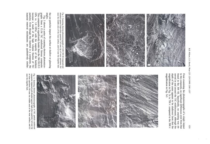
Development of a wear test for the evaluation of cemented carbides used in rotary drilling applications

Abstract

The appearance of cemented carbides has revolutionized the rock drilling industry. Nowadays,
virtually all the rock drilling bits use cemented carbide inserts. Their advantageous mechanical
characteristics enable the possibility of drilling extremely hard grounds at high penetration
rates.

Atlas Copco Secoroc AB is the world leader in the production of consumable rock drilling
equipment. Given its commitment to continuous research and development, the company is
constantly trying to find new ways to improve its products.

Within this ambit, the following project was done.

Its main purpose was the development of a half‐field test rig. This rig would be used to
simulate the real conditions found in rotary crushing drilling in order evaluate the wear
behaviour of different cemented carbide grades.

The dynamics of the rock drilling technique and its influence on wear mechanisms were
analyzed. The evaluation of worn drill bits was also done in order to gain understanding about
these mechanisms and how to simulate them most effectively.

Consequently, design specifications for the half‐field test were settled. With all the different
components duly chosen and designed, the project for the complete test rig was done.

Carlos Filipe Afonso Moura
Development of a wear test for the evaluation of cemented carbides used in rotary drilling applications

Acknowledgements:

In Sweden, I would like to thank

Atlas Copco Secoroc AB for this great opportunity

Lars M. Karlsson for supervising this project, for the constant availability and all the support

Claes Tigerstrand for choosing me for this position

The Materials R&D team for the daily company

The Top‐Hammer team for all the patience to answer my infinite questions

The workshop team for borrowing me all the tools I needed

The cemented carbides production team for showing me how things work

The human resources team for providing all the great conditions

In Portugal, I would like to thank

FEUP for the excellence of its education throughout all these years

Antonio Monteiro Batista for all the supervision at the faculty

Paulo Tavares de Castro for supporting this project

And finally the Eramus‐Internship program without which this project would not be possible

Carlos Filipe Afonso Moura
Development of a wear test for the evaluation of cemented carbides used in rotary drilling applications

Contents
                                                                                              Page:
1 ‐ Introduction                                                                                1

2 ‐ Cemented carbides                                                                           2
         2.1 ‐ Production                                                                       3
         2.2 ‐ Properties                                                                       6

3 ‐ Rotary rock drilling                                                                        9
         3.1 ‐ Rotary crushing drilling                                                        11

4 ‐ Rock drill wear and deterioration mechanisms                                               14

5 ‐ Cemented carbide testing                                                                   16
         5.1 ‐ Basic testing                                                                   17
         5.2 ‐ Intermediate testing                                                            20
                    5.2.1 ‐ Impact test                                                        20
                    5.2.2 ‐ Fatigue test                                                       20
                    5.2.3 ‐ Log test                                                           21

         5.3 ‐ Half‐field testing                                                              23
                    5.3.1 ‐ Dog‐collar test rig design and specifications                      23
                               5.3.1.1 ‐ Abstract                                              23
                               5.3.1.2 ‐ State‐of‐art                                          23
                               5.3.1.3 ‐ Requirements                                          24
                               5.3.1.4 ‐ First solutions – Vertical turret lathe               25
                               5.3.1.5 ‐ First solutions – Column shaping machine              26
                               5.3.1.6 ‐ In‐house solution                                     27
                               5.3.1.7 ‐ Frame                                                 28
                               5.3.1.8 ‐ Turntable                                             29
                               5.3.1.9 ‐ Size of the rock                                      31
                               5.3.1.10 ‐ Table cylinder                                       32
                               5.3.1.11 ‐ Floor guiding system                                 34
                               5.3.1.12 ‐ Tool guiding system                                  35
                               5.3.1.13 ‐ Tool cylinder                                        36
                               5.3.1.14 ‐ Dog‐collar                                           37
                               5.3.1.15 ‐ Tool holder                                          38
                               5.3.1.16 ‐ Complete rig                                         39

                    5.3.2 ‐ Impeller‐in‐drum test rig design and specifications                41
                               5.3.2.1 ‐ Abstract                                              41
                               5.3.2.2 ‐ Existing Drum                                         42
                               5.3.2.3 ‐ Test specimens attainment                             42
                               5.3.2.4 ‐ New press tool                                        42
                               5.3.2.5 ‐ Old press tool                                        43
                               5.3.2.6 ‐ Paddle holder                                         44
                               5.3.2.7 ‐ Whole assembly                                        45

         5.4 ‐ Field testing                                                                   47

6 ‐ Wear analysis                                                                              48

7 ‐ Conclusions                                                                                50

References                                                                                     51
List of figures                                                                                52
Attachments                                                                                    54

Carlos Filipe Afonso Moura
Development of a wear test for the evaluation of cemented carbides used in rotary drilling applications

1 ‐ Introduction

Ground drilling has been done for over 3000 years. Since the pulley system used in the ancient
China [fig1], the drilling technique has been constantly developing. The increasing demands of
mining and construction industries have stimulated this development. Nowadays, the state‐of‐
art makes it possible to drill oil wells in the middle of the ocean at high depths, to blast holes in
the extremely hard grounds of iron ore mines. Though, most of these capacities would not be
possible without the appearance of cemented carbides. These hard materials have made it
possible to build tools for drilling in virtually any sort of ground.

       [fig1] – Pulley percussive drilling system used in the ancient China 3000 years ago

Given its importance, these hard‐metals have been intensively studied in the last fifty years.
Several authors have contributed for this purpose, and extensive information about this
subject can be found in the literature. Despite this fact, a lot of work remains to be done in the
field of the wear testing. There is no standard wear test to simulate real drilling conditions,
thus, most of the companies have to rely on the basic material testing or develop their own
testing methods.

Carlos Filipe Afonso Moura
                                                                                                    1
Development of a wear test for the evaluation of cemented carbides used in rotary drilling applications

2 ‐ Cemented carbides

Cemented carbides (or hardmetals) are composite materials, obtained by powder metallurgy.
From a technical point of view, tungsten‐carbide (WC) based hardmetals are by far the most
important group [3]. One of the most common associations is the WC‐cobalt cemented carbide.
It is a metal matrix composite where tungsten carbide particles are the aggregate and metallic
cobalt serves as the matrix. The extremely hard tungsten carbide provides the overall hardness
and wear resistance whereas the ductile cobalt (Co), binder phase, will promote the
toughness.

Cemented carbide tools render quite useful when employed in rock drilling and metal
machining applications where other materials would wear away much faster. They can
withstand high stresses, high temperatures and maintain their shape after several working
cycles. For cemented carbides are more brittle than other tool materials, they are generally
used as small inserts to be assembled on the shank tool made of a more ductile material,
generally steel. This renders tools much cheaper, and damaged inserts can be replaced with
ease.

High speed steel tools and some rock drilling inserts are sometimes coated in order to improve
surface hardness and lubricity, as well to lower the working temperatures. Though the life time
is increased, these coated inserts are seldom used in rock drilling applications due to their high
price ‐ a diamond coated insert can cost up to four times more than a standard insert –
generally they are used in the oil industry where larger depths are to be achieved with one
single bit.

Being the dominant material in rock drilling tools [4], the WC‐Co cemented carbide will be
considered in the following sections.

                                 [fig2] – Cemented carbide tools

Carlos Filipe Afonso Moura
                                                                                                    2
Development of a wear test for the evaluation of cemented carbides used in rotary drilling applications

2.1 ‐ Production

Tungsten‐cobalt carbide is produced thru a sintering process. The WC powder with certain
grain size ‐ from 0.5 µm (fine grain) up to 5 µm (extra coarse grain) [1] ‐ is mixed with the
desired proportion of cobalt powder and milled together with press agents and milling fluid [2]
(other elements like VC, Cr3C2 or TaC can also be added as grain growth inhibitors) [6,8]. This
slurry mixture will then be spray‐dried, i.e. pumped thru an atomiser nozzle producing fine
droplets into a drying chamber. Here, a hot nitrogen atmosphere will dry the droplets
producing well mixed agglomerates [fig3].

 [fig3] ‐ Electron microscope image of the agglomerates resulting from spray drying. Metal and carbide
 powder with a grain size of 1‐3 µm was used, along with PEG (Polyethylene glycol) as press agent. The
                               agglomerates average a 100 µm diameter [6].

A powder compaction press is used to obtain the green bodies (pieces of compacted power
held together by the press agent). The agglomerate powder is poured into a vertical die cavity
with the required shape, pressed with a punch tool and finally ejected from the cavity.

The green bodies are sintered at 1350‐ 1500ºC after a preheating cycle at 300‐400ºC to burn
off the press agents [2]. At the highest temperature the cobalt melts and the WC carbide starts
to decompose to tungsten and carbon. During cooling this decomposition reverses leaving only
a small amount of dissolved tungsten and carbon that will strengthen the cobalt phase [2]. For
some rock drill inserts the whole sintering thermal cycle takes up to 15h. The duration of the
cycle is highly dependent on the insert size, geometry and composition.

Carlos Filipe Afonso Moura
                                                                                                         3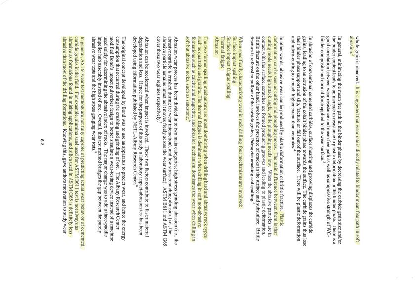
Development of a wear test for the evaluation of cemented carbides used in rotary drilling applications

                  [fig4] ‐ Simplified heating cycle used in cemented carbide sintering

A phenomenon that has to be taken in account during the project of new cemented carbide
inserts is the shrinkage i.e. a decrease in dimensions of the compact which occurs during
sintering. For example, a green chisel insert with approximate overall dimensions 12.2 x 21.4 x
48.9 mm measures 10.0 x 17.7 x 39.3 mm after sintering. This represents an average 18% of
linear shrinking, and approximately 44% of volume reduction. Generally, 17.5% of linear
shrinking is the reference value.

   [fig5] ‐ Dimensional comparison between green body and cemented carbide insert after sintering

Due to shrinkage, after sintering all the inserts must be ground to the required assembly
dimensions. The chisel above mentioned would be ground to the width of 9.9 mm. Tight
tolerances can be achieved with standard grinding machines [fig#].

                       [Fig6] ‐ Cemented carbide inserts ready to be assembled

Carlos Filipe Afonso Moura
                                                                                                    4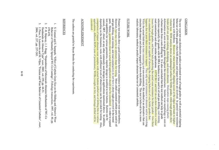
Development of a wear test for the evaluation of cemented carbides used in rotary drilling applications

The quality of the inserts must be frequently evaluated. Thus, sample inserts are frequently
collected, measured and weighed. Both the magnetic coercivity and the magnetic saturation
are also measured [See section 5.1].

Carlos Filipe Afonso Moura
                                                                                                    5
Development of a wear test for the evaluation of cemented carbides used in rotary drilling applications

2.2 ‐ Properties

The cemented carbide materials provide a unique combination of hardness and toughness.
Their mechanical properties are highly dependent on the relative proportions of cobalt and
WC present in its structure. Although many grades for specialised applications lie outside these
ranges, in rock drilling applications the current grades range from 6% to 15% of cobalt. These
values depend on the ground to be drilled, insert functional role and drilling method. The WC
grain size also plays an important role defining the material properties.

In accordance with its non‐centrosymmetric crystal structure, the microhardness of WC is
highly anisotropic. Thus, it’s not surprising that microhardness values measured at arbitrary
orientations show a large scatter, and room temperature microhardness values given in the
literature have a wide range [3], from 1300HV* up to 2300HV [Fig7] [1]. Until the mid 1960s WC
was assumed to be perfectly brittle. There is a lot of evidence, however, that WC shows
appreciable plastic deformation. Other essential features of WC are the extremely high elastic
modulus, around from 400GPa to 650GPa [1], and its high thermal conductivity.

[fig7] ‐ The non‐centrosymmetric hexagonal WC crystal structure.Basal planes with 2300 HV and crystal
                                     prism plans with 1300 HV.

Cobalt is used nearly exclusively in cemented carbide production (more than 95%) because of
its outstanding wetting and adhesion as well as to its advantageous mechanical properties [3].
The bulk hardness of cobalt is bellow 100 HV, but nanohardness tests have shown that Co‐
binder close to WC‐grains is about four times harder than in the bulk [9]. Not much importance
is paid to the Co powder properties for they are lost during milling and liquid‐phase sintering
and thus do not influence the properties of the binder phase.

* All the hardness values in this thesis refer to HV30, i.e. Vickers hardness test with an indent load of 30kg

Carlos Filipe Afonso Moura
                                                                                                                 6
Development of a wear test for the evaluation of cemented carbides used in rotary drilling applications
The relationship between the different properties and compositions is roughly expressed in
the following table [fig8]. Although this table is valid in general, there are some deviations
which must be considered. Higher binder content at a given hardness, combined with a lower
average WC grain size, does not necessarily mean a higher toughness. In the lower hardness
range this relationship doesn’t even exist. At the higher range, on the other hand, a higher
binder can reduce the carbide contiguity and thus improve the hardness to toughness
relationship [6]. It has also been found that ultra fine grained hardmetals produced from
nanocarbide powders have much superior toughness, particularly at hardness levels above
1500HV, compared to conventional hardmetals [8].
[fig8] ‐ Relationship between the different properties of cemented carbides
The overall hardness of cemented carbides ranges approximately from 700 HV, for a grade
with 25% cobalt and 5 µm coarse grain size, up to 2200 HV, for a 5% cobalt grade with
submicron WC grain size [1].
Toughness is generally evaluated through the Palmqvist method:
W = Toughness (N/m)
P L = Sum of the crack lengths at the corners of a Vickers hardness indentation (m)
W=
L
P = Indent load (N)
[fig9] ‐ Palmqvist indent with crack lengths
Carlos Filipe Afonso Moura
7Development of a wear test for the evaluation of cemented carbides used in rotary drilling applications
One of the most important properties of cemented carbides is the fracture toughness. It is
denoted KIc, plain‐strain fracture toughness, and describes the ability of a material containing a
crack to resist fracture. The subscript Ic denotes mode I crack opening under a normal tensile
stress perpendicular to the crack, since the material can be made thick enough to resist shear
(mode II) or tear (mode III).
The following formulae were proposed by different authors and can be used to convert the
Palmqvist data into fracture toughness values ( MPa m ) [6, 8]:
Shetty et al.
HP
K Ic = 0.0889
L
Where H = Vickers hardness (Nm‐2)
P = Indent load (N)
L = Total crack length (m)
Peters
0.000319 P
K Ic =
a l
Where P = Indent load (N)
l = single crack length (m)
a = one half indent diagonal length (m)
Depending on the grades, typical fracture toughness values for cemented carbides lie between
[1]
5 MPa m and 26 MPa m .
Carlos Filipe Afonso Moura
8Development of a wear test for the evaluation of cemented carbides used in rotary drilling applications
3 ‐ Rotary rock drilling
Revolutionized by the appearance of cemented carbides, rock drilling plays an essential role in
mining, exploration and water well industries. There are several different applications that
need different kinds of drilling equipment and performance. The drilling method has been
established for some time, and well proven techniques are seldom replaced by new methods.
Being the world’s leader in the manufacturing of rock drilling bits, Atlas Copco Secoroc divided
its surface drilling product range in two main groups: rotary percussive and rotary crushing
drilling.
Rotary percussive drilling
Top hammer method: Down‐the‐hole method:
As the name “tophammer” The hammer is situated
implies, the rock drill is down the hole in direct
situated on the rig and contact with the drill bit. The
works on the top of the hammer piston strikes the
drill string. The impact drill bit resulting in an
energy of the rock drill efficient transmission of the
piston is transmitted to the impact energy and
drill bit in the form of insignificant power losses
shock waves. Although the with the hole depth. The
method is fast in good rock method is widely used for
conditions, the hole depth drilling long holes, not only
and straightness are for blasting, but also for
comparatively limited. water wells, shallow gas and
oil wells, and for geo‐
thermal wells. From an
environmental point of view,
[fig10] [fig11]
the noise emissions and
vibration from DTH drilling
are comparatively low.
Carlos Filipe Afonso Moura
9Development of a wear test for the evaluation of cemented carbides used in rotary drilling applications
COPROD® system: Rotary crushing drilling
Rotation is provided by
a hydraulic or electric
The rock drill is situated on
motor driven gearbox,
the feed beam on the rig
called rotary head that
and impact energy is
moves up and down the
imparted from above.
tower via a feed system,
Threadless impact rods are
generating the pulldown
stacked inside the
required to give
threaded drill pipes. The
sufficient weight on the
impact rods are used solely
bit. Flushing of drill
to transmit impact energy
cuttings between the
and feed force, while the
wall of the hole and the
drill pipes transmit
drill rods is normally
rotation. COPROD
made with compressed
combines the speed of
air.
tophammer drilling with
the hole straightness of
the down‐the‐hole
[fig12] [fig13]
method.
Carlos Filipe Afonso Moura
10Development of a wear test for the evaluation of cemented carbides used in rotary drilling applications
3.1 ‐ Rotary crushing drilling
The prime difference from other drilling methods is the absence of percussion. Rotary cutting
using fixed type claw or drag bits, is mainly used for soft rock which is cut by shearing. Rotary
crushing uses tricone bits relying on crushing and spalling the rock. This is accomplished by
transferring downforce, known as pulldown, to the bit while rotating in order to drive the
teeth into the hole bottom as the three cones rotate around their respective axis. The softer
the rock, the higher the rotation speed. The drill rigs need to be heavy in order to avoid the
lifting of the jacks, which means they
are less flexible and not very well
suited for drilling at different angles.
Generally, drilling bellow 152 mm is
best accomplished by percussive
drilling unless prevailing rock
conditions are suited for rotary
cutting. Rotary crushing is the prime
choice for large diameter holes,
above 254 mm in open pit mining,
overburden stripping at coal mines,
and deep well drilling.
[fig14] – Rotary crushing drill rigs
Flushing of the drill cuttings between the wall of the drill hole and the drill
rods is normally made with compressed air.
[fig15] ‐ Air pathway through the nozzles and lugs; Flushing of the drill cuttings
Carlos Filipe Afonso Moura
11Development of a wear test for the evaluation of cemented carbides used in rotary drilling applications
[fig16] – Rotary bit ready to be used
The tricone drill bits are composed of three cones. The cones make up the cutting elements of
the rock bit and are comprised of the following:
WC carbide inserts – which are pressed into the softer steel material with interference fit to
hold them in place;
Cone thrust button – made of a wear resistant material used to take axial loads;
Outer cone shell – Insert’s bores and cone grooves;
Cone bore – internal ball and roller bearing races;
[fig17] – Rotary bit cone with inserts
The lugs are coupled in three by 120º and welded together to form the bit body and the pin
connection. The bearing inner races and the nozzle holders are machined directly in the lugs.
The shirttail protection inserts prevent the side wear caused by the rock cuttings flushed from
the bottom of the hole.
Carlos Filipe Afonso Moura
12Development of a wear test for the evaluation of cemented carbides used in rotary drilling applications
[fig18] – Rotary bit lug
[fig19] – Cut view of complete rotary bit
Carlos Filipe Afonso Moura
13Development of a wear test for the evaluation of cemented carbides used in rotary drilling applications
4 ‐ Rock drill wear and deterioration mechanisms
The wear and deterioration of cemented carbides is an intricate subject of the utmost
importance that has been actively investigated in the last few years. Many authors have
contributed with considerable developments in this field. Though, given its complexity, there
are still many questions remaining to be solved.
For it’s not part of the main theme of this work, this subject will only be briefly discussed.
The first stage of the cemented carbide wear is the surface deterioration. It can be caused by
several different mechanisms, found in the following groups [1]:
‐ Rock cover formation, rock intermixing and penetration – small particles of rock penetrate
the insert structure creating both a continuous outer layer of mixed material as well as deep
channels filled with rock.
[fig20] – Mixed surface layer and rock penetration in the cemented carbide structure
‐ Embrittlement and degradation of the binder phase – the presence of cyclic stress, by shifting
temperature or load, will lead to material fatigue. The subsequent structural changes will
promote the appearance of cracks, and thus surface deterioration.
‐ Composite‐scale crack formation – a thermal wear mechanism. It compasses the known
“Reptile skin formation”. This is a particular deterioration mechanism found when drilling soft
rock types like the magnetite. To avoid catastrophic cracks, the drills inserts have to be
regularly ground down to the bottom of the valleys.
[fig21] – Reptile skin formation found in cemented carbide insert used to drill magnetite
Carlos Filipe Afonso Moura
14Development of a wear test for the evaluation of cemented carbides used in rotary drilling applications
‐ Cracking of single WC grains – plastic deformation and fragmentation of carbide grains can
happen whilst drilling hard rock types, especially under abrasive conditions.
[fig22] – Cemented carbide showing plastically deformed WC grains
‐ Oxidation and corrosion of WC grains
These deterioration mechanisms will
led to the detachment of cemented
carbide particles from the insert
surface. Sometimes there’s
catastrophic failure of the inserts
without previous deterioration. This
can be caused by the presence of some
hard material in the hole bottom. This
hard material, generally coming from
broken defective inserts, will hit the
drill inserts and cause them to break.
These broken insert particles can lead
to the destruction of the whole drill bit.
For this reason the production of
cemented carbide inserts has to
undergo tight quality control.
[fig23] – Detachment mechanisms in cemented carbide inserts
Carlos Filipe Afonso Moura
15Development of a wear test for the evaluation of cemented carbides used in rotary drilling applications
5 ‐ Cemented carbide testing
The evaluation of cemented carbides and the comparison of different grades are important
matters that have to be taken in account whilst producing and developing the drill inserts. The
testing methods were divided into four different groups according to their complexity and
proximity to real drilling conditions.
[fig24] – Cemented carbide testing chart
Carlos Filipe Afonso Moura
16Development of a wear test for the evaluation of cemented carbides used in rotary drilling applications
5.1 ‐ Basic testing
Standard tests
There are several organizations developing and publishing standardized procedures for
materials testing. ASTM International, originally known as American Society for Testing and
Materials, is one of the best known organizations of this kind that offers a wide range of
standards related to the cemented carbide testing. Another highly respect organization is the
International Organization for Standardization – ISO. For these are probably the best known
worldwide organizations, their publications are followed by most of the cemented carbide
producers. The most commonly measured parameters to assess quality and define application
areas are described bellow:
Porosity ‐ Residual Porosity is determined by visually examining the polished surface of a
sintered sample at 100X or 200X magnification. Ratings for “A” type porosity (pores less than
10 microns in diameter), “B” type porosity (pores larger than 10 microns in diameter), and “C”
type porosity (carbon inclusions) are determined by comparing the size and frequencies of
each pore type in the sample with those in standard photographs. Each standard photograph is
associated with a numerical rating that is used to represent the porosity levels in the sample.
In general, edge strength and toughness decrease as the level of residual porosity increases. At
high levels of porosity, the wear resistance of the product may also be adversely affected.
ASTM B276:05e1 ‐ Standard Test Method for Apparent Porosity in Cemented Carbides
ISO 4505:1978 – Hardmetals ‐ Metallographic determination of porosity and uncombined
carbon
Magnetic saturation ‐ Magnetic Saturation is the degree to which the metal binder in a
cemented carbide is saturated with carbon. It is most useful for materials having a cobalt
binder. For a known cobalt content magnetic saturation values indicate how much carbon the
cemented carbide contains – from unacceptably low values that indicate the presence of an
undesirable carbon‐deficient phase (known as eta phase) to unacceptably high values
indicating the presence of free carbon (carbon “porosity”) in the product. Magnetic saturation
is sometimes used as an indicator of relative strength among lots of a specific grade.
ASTM B886:03(2008) ‐ Standard Test Method for Determination of Magnetic Saturation (Ms)
of Cemented Carbides
Carlos Filipe Afonso Moura
17Development of a wear test for the evaluation of cemented carbides used in rotary drilling applications
Magnetic Coercivity ‐ Coercive Force is the strength of the magnetic field required to
demagnetize a fully magnetized cemented carbide sample. Coercive force is typically
measured in oersteds (Oe). The coercive force measurement depends on many factors
including composition, sintered grain size distribution, residual porosity levels, and others. It is
sometimes used as an alternative indication of hardness, but is best interpreted in
combination with other properties as a measure of overall grade uniformity. The mean free
path, which is a measure of the average thickness of cobalt between the WC grains, can be
also indirectly determined by measuring the magnetic coercivity force [1].
ASTM B887:03 ‐ Standard Test Method for Determination of Coercivity (Hcs) of Cemented
Carbides
ISO 3326:1975 ‐ Hardmetals ‐ Determination of (the magnetization) coercivity
Hardness ‐ Hardness is the resistance of a cemented carbide to penetration by a diamond
indenter under a specific load. It is measured on the Rockwell A (Ra) scale in the US and on the
Vickers (HV10 or HV30) scale in Europe and elsewhere. Hardness is primarily a function of
composition and grain size with higher binder metal contents and coarser tungsten carbide
grain sizes producing lower hardness values. Conversely, low binder contents and fine grain
sizes produce high hardness values. Hardness is directly related to abrasive wear resistance.
Rockwell Hardness
ASTM B294:92(2006) ‐ Standard Test Method for Hardness Testing of Cemented Carbides
ISO 3738‐1:1982 ‐ Hardmetals ‐ Rockwell hardness test (scale A) ‐ Part 1: Test method
ISO 3738‐2:1988 ‐ Hardmetals ‐ Rockwell hardness test (scale A) ‐ Part 2: Preparation and
calibration of standard test blocks
Vickers Hardness
ISO 3878:1983 ‐ Hardmetals ‐ Vickers hardness test
ASTM C1327:08 ‐ Standard Test Method for Vickers Indentation Hardness of Advanced
Ceramics
Transverse Rupture Strength ‐ Transverse Rupture Strength (TRS) is a measure of the tensile
strength of a cemented carbide in a three point bending test performed on standard
rectangular bars. It is reported in units of pounds per square inch (psi), or in Newtons per
square millimeter (N/mm2). TRS is perhaps the best measure of the relative utility of individual
production batches since it surveys a reasonable volume of material and will detect low levels
of critical internal defects. Products having relatively high TRS values are generally applied
where shock, impact, or failure by breakage are factors
Carlos Filipe Afonso Moura
18Development of a wear test for the evaluation of cemented carbides used in rotary drilling applications
ASTM B406:96(2005) ‐ Standard Test Method for Transverse Rupture Strength of Cemented
Carbides
ISO 3327:1982 ‐ Hardmetals ‐ Determination of transverse rupture strength
Density ‐ Density is the weight per unit volume of a cemented carbide measured in grams per
cubic centimeter (g/cm3). It is essentially the weighted average of the densities of all of the
components contained in the product and is therefore a check on its composition.
ASTM B311:93(2002)e1 ‐ Test Method for Density Determination for Powder Metallurgy (P/M)
Materials Containing Less Than Two Percent Porosity
ISO 3369:1975 ‐ Impermeable sintered metal materials and hardmetals ‐ Determination of
density
Grain size – The average grain size is determined by visually examining photomicrographs of
the cemented carbide surface. It depends merely on the chosen WC powder and has great
influence on the hardness and toughness. The introduction of the spray conversion process
for the production of WC‐Co powders in the size range 20‐30nm has resulted in the
development of “nanocrystalline” hardmetals whose properties have considerably improved in
comparison to those similar coarse grained materials.
ISO 4499‐1 ‐ Hardmetals ‐ Metallographic determination of microstructure ‐ Part 1:
Photomicrographs and description
ISO 4499‐2 ‐ Hardmetals ‐ Metallographic determination of microstructure ‐‐ Part 2:
Measurement of WC grain size
Non‐standardized tests
Palmqvist indentation toughness – refer to section 2.2
Carlos Filipe Afonso Moura
19Development of a wear test for the evaluation of cemented carbides used in rotary drilling applications
5.2 ‐ Intermediate testing
5.2.1 ‐ Impact test
In this test the basic principle is to drop the test specimen against a fixed object or surface. The
impact energy is then measured, and the specimen is dropped again a given number of times,
or until it breaks. There are commercially available rigs designed to perform these tests. They
can monitor and control several parameters like the impact energy, impact velocity, number of
impacts until failure, temperature, etc. These machines are distributed with specific software
for data handling. This renders the acquisition of practical results simple and expeditious.
Though, these machines are generally expensive.
[fig25] ‐ Impact test machine with controlling and data acquisition/handling system
5.2.2 ‐ Fatigue test
Here, fatigue load is induced in the test specimens. Like the previous, there are commercially
available solutions ready to use. They rely generally on a hydraulic loading system and precise
load cells specifically designed for this purpose. Yet again, like most of the material testing
equipment of this sort, these test rigs are generally expensive.
[fig26] ‐ Fatigue test machine with controlling and data analysis software. Specifically designed load cell
Carlos Filipe Afonso Moura
20Development of a wear test for the evaluation of cemented carbides used in rotary drilling applications
5.2.3 ‐ Log test
This test is currently being performed by several hardmetal producers. For there is no
commercially available solution, all the test rigs are built in‐house. This is an abrasion test and
the basic principle is to press a hardmetal test specimen against a rotating stone log placed in a
horizontal lathe. The specimen then is moved along the log surface for some time, and finally
removed and analysed.
[fig27] ‐ Representation of horizontal lathe performing the log test
In order to prevent excessive rubbing, full inserts cannot be used. The smaller test specimens
are generally obtained cutting the insert three times in the longitudinal direction.
[fig28] ‐ Full insert perspective view, top view with cutting lines and final test specimen
In order to prevent the log from breaking, the tests have to be stopped when a specific
minimum diameter is reached. A 150 mm wide log is worn down solely down to 85 mm, i.e.
only 45% of the total rock volume is actually used.
[fig29] ‐ Initial and worn log
Carlos Filipe Afonso Moura
21Development of a wear test for the evaluation of cemented carbides used in rotary drilling applications
Advantages: Disadvantages:
‐ Low maintenance and purchase costs ‐ Log shaped rock required
‐ Simple process ‐ Only 43% of the rock volume is used
‐ Quantitative and qualitative results ‐ Laborious process to obtain test specimens
‐ Test specimens different from production inserts
[fig30] ‐ Advantages and disadvantages of the log test
Carlos Filipe Afonso Moura
22Development of a wear test for the evaluation of cemented carbides used in rotary drilling applications
5.3 ‐ Half‐field testing
5.3.1 ‐ Dog‐collar test rig design and specifications
5.3.1.1 ‐ Abstract
This test is used to simulate rotary crushing drilling. It is an impact‐abrasive wear test and
probably the best approximation method to the real conditions. The test rig is a rather
complex mechanism and is not commercially available. Despite this fact there are several
hardmetals producers performing and investing in this test.
Basically the cemented carbide inserts are hot fitted around a steel disc in a way that
resembles a dog‐collar. This collar in then pressed against, and moved along a rotating stone
with a flat surface. The friction will force the collar to rotate around its axis [fig31].
[fig31] – Dog‐collar test elements
5.3.1.2 ‐ State‐of‐art
Most of the companies performing this test use a modified vertical turret lathe. They simply
build a dog‐collar holder and assemble it in the modified turret. The position of the tool and
the rotational speed are the only two variables to be controlled. For this test requires a large
volume of rock to be handled, the lathes are rather bulky and heavy [fig32].
[fig32] – Vertical lathe with rock and silhouette as dimensional reference
Carlos Filipe Afonso Moura
23Development of a wear test for the evaluation of cemented carbides used in rotary drilling applications
[fig33] – Dog‐collar test being performed. The tracking in the rock surface is clearly visible.
5.3.1.3 ‐ Requirements
• Simulate real conditions as close as possible:
‐ A maximum of 500kg of load per insert. Though this value is seldom reached and not
recommended in practical drilling, the test rig should reach it in order to evaluate
future grades with improved qualities. A maximum of 175Kg per mm of bit diameter is
the goal to be reached as rule of thumb for the maximum pull down force per bit.
140Kg/mm is the maximum recommended value.
‐ 43 insert hits per second – yet again, this is a maximum value. It corresponds to an
average bit rotational speed of 150 RPM.
‐ Cone shift of two degrees – The tricone bits are produced with a cone shift of
approximately 2 degrees from its axis of rotation. This is done in order to promote
rubbing between the bit and the rock, thus leading to abrasive wear.
[fig34] – Cone shift around its centre of gravity. This deviation from the axis of rotation will promote the
abrasive wear.
• Compact overall dimensions
• Ease of controlling
Carlos Filipe Afonso Moura
24Development of a wear test for the evaluation of cemented carbides used in rotary drilling applications
• Simple and reliable construction
• Meet safety criteria
• Low maintenance
• Low purchase and operation costs
• Repeatability of test conditions
• Flexibility to simulate different conditions
5.3.1.4 ‐ First solutions – Vertical turret lathe
The first solution to be taken in account was to do the same thing as the competitors, i.e. using
a modified vertical lathe. After a market survey, some problems arose:
- The new lathes are too expensive: all the new lathes cost more than the budget for the
whole project, i.e. 50.000€. Thus, the lathe would have to be bought in a second hand
state which would certainly void the warranty;
- Lathes are high precision equipment: for precision is not a requirement of this test rig, a
considerable expense would have to be paid for a useless feature;
- Second hand fully‐functional lathes are still expensive – the price tag for these second
hand lathes goes from 40.000€ (for a non‐functional old lathe), up to 330.000€ (for fully‐
functional lathe with control system);
[fig35] – Second hand vertical turret lathes found at www.machinestock.com
- The acme threads cannot take much load: the tool holder is guided using acme threads.
These threads are good for high precision displacements but they are not designed to
take high loads.
Carlos Filipe Afonso Moura
25Development of a wear test for the evaluation of cemented carbides used in rotary drilling applications
[fig36] – Acme thread used to guide and move the tool holder in vertical lathes
- Bigger threads require bigger lathe: in order to take the required load, the guiding acme
threads would have to be bigger. These oversized threads can only be found in big lathes;
- No need for turret, it would have to be removed: most of the lathes come with a turret
for quick tool exchange. For it is not necessary, it would have to be removed or modified;
- Control system would have to be added: for fully functional lathes with control system
are too expensive, a control system would have to be developed. This couldn’t be done
without considerable work and the costs would be probably high.
- Position controlling and not load control: one of the main issues of this solution is that the
lathes control the tool position and not the load on the tool. This fact would surely
increase the gap between the real and the simulated drilling conditions.
Although most of these issues could be solved, they would certainly increase the overall
expenses above the budget.
5.3.1.5 ‐ First solutions – Column shaping machine
[fig37] – Column shaping machine
Carlos Filipe Afonso Moura
26Development of a wear test for the evaluation of cemented carbides used in rotary drilling applications
Another solution that was also taken in account was to use a column shaping machine. These
commercially available machines are quite common in the stone industry. They are used to
shape circular columns. There of some advantages worth of notice, namely: the tool holder has
the two required degrees of freedom, and the turntable is designed to handle stone. Given
their low precision and simple construction these machines are also available for a low price
(approximately 4.000€). But, like in the previous solution, some problems came to discussion:
- The tool holder is not designed to take high loads: it would have to be modified;
- Feeble structure to take a high load on the tool: the frame design would not permit high
loads on the tool holder, it would have to be reinforced;
- Position controlling and not load control: as in the previous solution this would be one of
the main issues;
- The guiding rails are designed to hold solely the cutting tool, an angle grinder. Therefore,
this guiding system would have to be substituted or reinforced;
Due to the fact that all the needed modifications would probably raise safety issues, the
development of this solution was not resumed.
5.3.1.6 ‐ In‐house solution
Finally, the idea of projecting the whole test rig came to mind. It could be designed and
assembled in‐house and all the components would have to be chosen from different suppliers.
Some parts would have to be machined and a considerable amount of time would have to be
spent. Despite these facts this was feasible project that would meet all the requirements and
probably keep the overall expenses under the budget. After several different proposals a final
sketch was considered to be the simplest and easiest solution [fig38].
[fig38] – Dog‐collar test rig final sketch
Carlos Filipe Afonso Moura
27Development of a wear test for the evaluation of cemented carbides used in rotary drilling applications
In this sketch we can see the main components and the basic mechanism. The rock would be
placed in the rotary table. This table would be placed over a linear guide and moved to side
with a pneumatic or hydraulic cylinder. The tool would be vertically moved with another
cylinder, and held in the right position with a tool guide.
The final test rig is shown in the next figure. In the next sections all the different components
will be discussed.
[fig39] – Final test rig with all the different components indicated
5.3.1.7 ‐ Frame
The frame would be made of structural steel. Given its simplicity, robustness and low weight,
I‐beams could be used. The structure would be welded together and bolted to the ground. A
standard I‐beam with the following dimensions would be used:
Standard wide flange I‐beam W10x68 (10” wide, 68Lbs/inch)
Section: 254 x 254 mm, web: 11.94mm, flange: 19.56mm
Carlos Filipe Afonso Moura
28Development of a wear test for the evaluation of cemented carbides used in rotary drilling applications
[fig40] – Test rig frame
5.3.1.8 ‐ Turntable
For the rock rotational movement the table would have to meet the following requirements:
- Built‐in rotational speed control system;
- High loading capacity;
- Possibility of taking non‐centred loading;
- Rotational speed over 25 RPM;
- Robustness for rock handling;
- Low maintenance over time;
The first idea was to use rotary table like the ones used in the vertical lathes. These tables can
easily take non‐centred load and reach high velocities. Although, given their high precision,
these tables are rather expensive. For most of them are hydraulically actuated, they seldom
come with a speed control system. For these reasons, this idea was abandoned.
The second idea was to buy a turntable. For no precision is required, these are generally less
expensive and can be bought with the control system. The main problem was that most of the
turntables are designed to take exclusively centred load, and when they’re not, the load
capacity is rather small.[fig41]
Carlos Filipe Afonso Moura
29Development of a wear test for the evaluation of cemented carbides used in rotary drilling applications
[fig41] – Rotary table hydraulically actuated and turntable for centred loading.
The final choice was to use a depalletizer – a turntable used in uncoiling applications [fig42].
With a table‐top diameter of 1320 mm it can reach 28 rpm. This is a considerable value taking
the maximum load into account ‐ approximately 5440 Kg.
[fig42] ‐ Depalletizer – a turntable used in uncoiling applications
For the rotating table‐top is supported in its periphery by four ball bearings, this table can take
non‐centred load without any particular problem. Instead of the central axel the table‐top is
guided with two side rollers and a clever torque transfer system. This leverage‐based system
will increase the friction between the driving well and the table‐top with the increase of the
resistant torque [fig43].
Carlos Filipe Afonso Moura
30Development of a wear test for the evaluation of cemented carbides used in rotary drilling applications
[fig43] – On the left picture we can see the turntable frame with the four support points and two guiding
rollers. The driving wheel is connected to the motor and its outer surface is made of (red) rubber in
order to promote friction. The picture on the right shows the turntable model top view with the motor
(green) placed in a leverage rod that, due to rotation, will push the driving wheel against the table inner
driving side.
[fig44] – Turntable model side view
These tables are reasonably cheap, and the producer (http://www.norwalkinnovation.com/ )
claims they’re maintenance free. They are also quite compact (400 mm of height), and they
come with built‐in velocity control system. The power output of 1.5KW would be enough to
overcome the rock inertia and the dog‐collar friction against the rock.
5.3.1.9 ‐ Size of the rock
The rock samples used to perform this test have to be dimensioned as function of the table
loading capacity. Thus, for a maximum tool load of 1000 Kg, the maximum advisable rock
weight would be: 5440 – 1000 = 4440 Kg. For an average rock density of 14.4 g/cm3 (density of
granite) the overall dimensions would have to within the graphic area [fig45].
Carlos Filipe Afonso Moura
31Development of a wear test for the evaluation of cemented carbides used in rotary drilling applications
[fig45] – The rock dimensions would have to be within the yellow graphic area. On the left there’s a side
view of the turntable with the rock (with the dimensions indicated by the red circle) on the top.
5.3.1.10 ‐ Table cylinder
A pneumatic solution was chosen for the turntable transverse movement. For no precision,
high velocity or high forces are required, a pneumatic cylinder could suit this application. The
seesaw movement could be controlled by a simple pneumatic system without the need of
electric components. There is a compressed air network in the laboratory where the test rig
would be placed.
It would have to be a double‐acting symmetric cylinder in order to have the same piston
velocity in both directions. And given this fact, it would have to be compact in order to fit
under the turntable.
[fig46] – Double‐acting symmetric cylinder
The first step was to do the cylinder dimensioning as function of the required forces:
1 ‐ Maximum weight to be moved:
The maximum turntable load is 5440 kg. The turntable weight is approximately 420 kg.
6.000 kg will be the considered the total maximum weight (W)
2 ‐ Maximum friction load:
According to the producer, the friction coefficient of the ball rail system is approximately
0.002 to 0.003, thus:
FF = 0.003 x 6000 x 10 = 180 N
Carlos Filipe Afonso Moura
32Development of a wear test for the evaluation of cemented carbides used in rotary drilling applications
[fig47] – Pneumatic cylinder dimensioning
3 – Given its dimensions compatible with the turntable size, the 80 mm piston cylinder was
considered:
Cylinder force, FC:
Network pressure = 5.5 bar ≈ 5.5 x 10⁵ Pa
Piston area ≈ 0,005 m2 ; Piston rod area ≈ 0,0005 m2
FC = (0,005 – 0,0005) x 5.5 x 105 ≈ 25.000 N
Considering an efficiency of 80% (usual value for pneumatic cylinders)
FC ≈ 20.000N
Applying Newton’s law, with A = system acceleration:
FC – FF = W x A
A ≈ 3, 3 m/s2
Theoretically, starting from a rest position this acceleration will allow the table to move 50 cm
in approximately 0.5 seconds. Although this value would not be achieved (due to the air supply
flow, tool friction, etc) in practical conditions, this value is high enough to confirm the cylinder
choice.
The pneumatic system would use a 4/2 way pneumatically actuated valve to control the piston
movement, commanded by two 3/2 way valves mechanically actuated that would be placed in
both ends of travel, thus making the cylinder return when it reaches those points [see
attachment #2].
Carlos Filipe Afonso Moura
33Development of a wear test for the evaluation of cemented carbides used in rotary drilling applications
[fig48] – Pneumatic diagram for the turntable seesaw acting system
[fig49] – Table with assembled cylinder
5.3.1.11 ‐ Floor guiding system
For the floor guiding system the choice was to use Bosch Rexroth linear motion technologies.
Bosch offers a comprehensive range of guide rails and runner blocks, virtually suitable for any
task involving linear motion and high loads.
Given the required loading capacity, the Ball Rail System was chosen. It uses a continuous row
of steel balls on both sides of the runner blocks. These are placed with preload in the guiding
rail, and the strip holders are assembled on both edges.
[fig50] – Ball rail system, the ball rows are visible on both sides
Carlos Filipe Afonso Moura
34Development of a wear test for the evaluation of cemented carbides used in rotary drilling applications
The chosen runner blocks and rails were:
Runner block ‐ Flanged normal standard width FNS:
• Size 20; Accuracy class N; 24400 N normal loading capacity; C1 Preload class
[fig51] – Runner block
Standard guide rails for mounting from above with rail seal and strip holder
• Size 20; Accuracy class N; Length: two rails with 1076 mm and one with 2250 mm
[fig52] – Guide rail with strip holders
5.3.1.12 ‐ Tool guiding system
For the tool guiding system the choice was to use Bosch Rexroth technology once more. The
Roller Rail System is guiding system that, instead of steel balls, uses cylindrical rollers. This
enables the maximum advisable loads in the runner block to be much higher.
The size choice would have to be done as function of the maximum torque in the fixing point.
Here, the runner block would be fastened to the frame, and the rail connected to the moving
tool.
While performing this test the dog‐collar rotates over the rock surface. In order to promote
abrasive wear there can be a shift in the collar preventing its axis of rotation from being
aligned with the rock centre. The friction between the dog‐collar and the rock surface won’t
probably reach such a high value, though, for security reasons the considered friction
coefficient will be = 1.
Carlos Filipe Afonso Moura
35Development of a wear test for the evaluation of cemented carbides used in rotary drilling applications
.
Mo = 1 x 10000 x 0.6 = 6000 Nm
For a runner block size 65, the maximum permitted Mo is 15.760Nm [fig53]. This value is
considerably higher than the maximum required torque, thus confirming this choice.
[fig53] – Maximum advisable loads and torques for the roller runner blocks given in the manufacturer
catalogue
5.3.1.13 ‐ Tool cylinder
The tool cylinder [fig54] has to reach the maximum required load of 1000kg. This value can be
easily obtained with a pneumatic cylinder connected to the air network available. Considering
a maximum air pressure of 5.5 bar, and an efficiency of 80%, with a piston diameter of 200
mm the load would be approximately 1380 Kg.
[fig54] – Tool cylinder
Although this value is above the maximum required, the choice of using the 200 mm piston
cylinder was made in order to avoid insufficient loading due to air network pressure drops.
Carlos Filipe Afonso Moura
36Development of a wear test for the evaluation of cemented carbides used in rotary drilling applications
The tool displacement and load could be controlled with a simple pneumatic system [fig55]. A
pressure control valve with manometer would allow the controller to determine the cylinder
force, and a directional valve would control the movement direction [see attachment #1].
Pressure (bar) Load (Kg)
2 500
3 750
4 1000
[fig55] ‐ Pneumatic diagram for the tool acting system. Table relating manometer pressure and tool
load.
5.3.1.14 – Dog‐collar
The dog‐collar would have 10 inserts. At 28 Rpm (rotational speed of the table), this will lead
to a maximum insert hit frequency of 41. Although this value is under the required, 43, the
difference is acceptable without considerable deviation from the real conditions. The number
of insert per dog‐collar could be reduced in order to decrease the radius, thus increasing the
hit frequency.
The inserts could be hot fitted around the steel prop disc, or, alternatively the disc could be
composed of two halves that would be bolted together, thus holding the inserts. This last
solution would simplify the process of exchanging the inserts, though it wouldn’t be as robust
as the first.
[fig56] – Dog‐collar with hot fitted inserts (on the left); dog‐collar with steel prop made of two halves
(on the centre and right)
Carlos Filipe Afonso Moura
37Development of a wear test for the evaluation of cemented carbides used in rotary drilling applications
5.3.1.15 ‐ Tool holder
The tool holder would keep the dog‐collar in a vertical position. Two tapered roller bearings
would take the vertical load while allowing the dog‐collar to rotate around its axis.
[fig57] – Dog‐collar holder. Complete view; complete view with transparent prop; exploded view
This tool holder would be assembled in the tool arm [fig58]. The arm is bolted to the guide rail
that would then be placed in the runner block and connected to the cylinder. The round shape
of the tool holder would allow its rotation in the tool arm, thus simulating the cone shift of the
drilling bits.
[fig58] – Tool arm with tool holder and guide rail
Carlos Filipe Afonso Moura
38Development of a wear test for the evaluation of cemented carbides used in rotary drilling applications
5.3.1.16 ‐ Complete rig
The complete test rig would thus be composed of all the previous elements.
The floor cylinder can be easily disconnected from the turntable. The turntable is then pushed
from under the frame, thus making rock loading and unloading an easier and safer operation,
without risks of damaging the tool [fig62].
The overall costs can be resumed in the following table:
Turntable 8.000 €
Table cylinder 580 €
Tool cylinder 1.750 €
Frame ≈ 1.000 €
Tool holder and bearings ≈ 2.000 €
Floor guide 990 €
Tool guide 500 €
Total estimated price 15.000€
[fig59] – Tool system
[fig60] – Tool system bolted to the frame: tool arm, tool holder, dog collar, pneumatic cylinder and
guiding system
Carlos Filipe Afonso Moura
39Development of a wear test for the evaluation of cemented carbides used in rotary drilling applications
[fig61] – Complete test rig with man silhouette for dimensional comparison
[fig62] – Test rig with table in the rock loading position
Carlos Filipe Afonso Moura
40Development of a wear test for the evaluation of cemented carbides used in rotary drilling applications
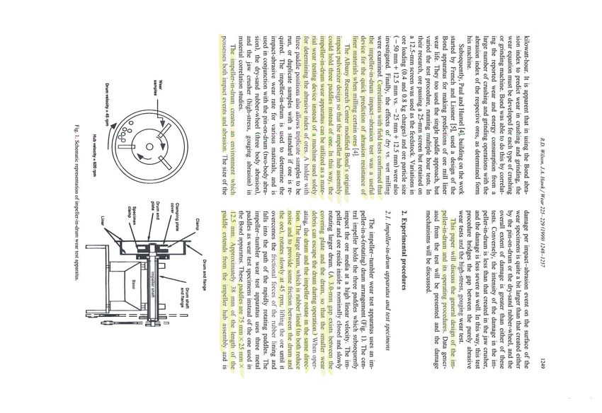
5.3.2 ‐ Impeller‐in‐drum test rig design and specifications
5.3.2.1 ‐ Abstract
The impeller‐in‐drum test is a both impact and abrasive wear test used to compare and
evaluate different cemented carbide grades. This test has been performed by some
laboratories with satisfactory results [10], [11].
It uses cemented carbide paddles that are assembled around a rotating support. This support
is placed inside a rotating drum which is rubber lined. The drum is filled with a known quantity
of rock and rotated slowly. Due to the rubber friction this rotation will make the stone go up
and fall over the paddles. The paddles are rotated in the same direction at high speed, thus
smashing the stone with the impacts.
This test is run for a certain time, after which the debris has to be taken out and replaced with
new stone. After some cycles the paddles are removed, weighed and the surface is analyzed.
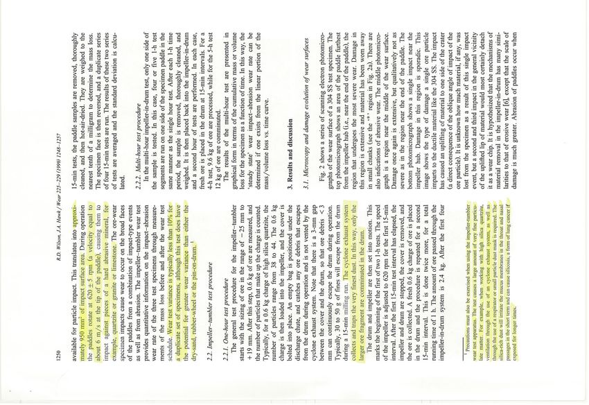
[fig63] – Impeller‐in‐drum test with paddle and drum rotational speeds [10]
Hexahedron cemented carbide paddles with the dimensions 75 x 25 x 12,5 mm [10], or 75 x 25 x
6 mm [11] have to be produced specifically for this test.
[fig64] – Cemented carbide test paddle
Carlos Filipe Afonso Moura
41Development of a wear test for the evaluation of cemented carbides used in rotary drilling applications
5.3.2.2 ‐ Existing Drum
One of the reasons this impeller‐in‐drum test was specifically chosen to be developed at Atlas
Copco Secoroc AB is that there is an available tumbling machine that can be used as drum.
[See attachment #5]
This machine has a rubber lined drum, with a velocity control system. It also has a hydraulic
system to pump water into the drum thru the hollow rotating axel [fig65].
[fig65] – Existing tumbling machine that can be used as drum. 3D model side view without the yellow
protection doors.
5.3.2.3 ‐ Test specimens attainment
Test paddles with the required dimensions have to be produced for this test. They can be
either supplied by some hardmetal company of produced in‐house. For the objective is to
evaluate different grades with accuracy, the idea of outsourcing was dropped.
The test paddles would have to be produced in the existing cemented carbide production unit.
Thus, powder press tools with the required green body shape would have to be obtained. Two
solutions were taken in account: produce a brand new press tool fully made of steel, or modify
an old existing tool partially made of cemented carbide.
5.3.2.4 ‐ New press tool
For the new press tool the choice was to design the green body die cavity with the dimensions:
90 x 30 x 12 mm that, after approximately 17,5% of shrinkage, would result in test paddles
with the dimensions: 74.3 x 24.8 x 9.9 mm.
Carlos Filipe Afonso Moura
42You can also read