Development of the Black Widow Micro Air Vehicle
←
→
Page content transcription
If your browser does not render page correctly, please read the page content below
AIAA-2001-0127

               Development of the Black Widow Micro Air Vehicle
                                   Joel M. Grasmeyer* and Matthew T. Keennon †
                                               AeroVironment, Inc.
                                              4685-3H Industrial St.
                                              Simi Valley, CA 93063

         This paper describes the development of the Black Widow Micro Air Vehicle (MAV) over
         the past 4 years. An MAV has generally been defined as having a span of less than 6 inches,
         and a mass of less than 100 grams. The Black Widow is a 6-inch span, fixed-wing aircraft
         with a color video camera that downlinks live video to the pilot. It flies at 30 mph, with an
         endurance of 30 minutes, and a maximum communications range of 2 km. The vehicle has
         an autopilot, which features altitude hold, airspeed hold, heading hold, and yaw damping.
         The electronic subsystems are among the smallest and lightest in the world, including a 2-
         gram camera, a 2-gram video downlink transmitter, and a 5-gram fully proportional radio
         control system with 0.5-gram actuators. A Multidisciplinary Design Optimization
         methodology with a genetic algorithm was used to integrate the MAV subsystems and
         optimize the vehicle for maximum endurance. Some of the potential missions for MAVs are
         visual reconnaissance, situational awareness, damage assessment, surveillance, biological or
         chemical agent sensing, and communications relay. In addition to these military missions,
         there are several commercial applications, such as search and rescue, border patrol, air
         sampling, police surveillance, and field research.

                    Introduction*                                             Early Prototypes
The first feasibility study for Micro Air Vehicles          In the early stages of the Black Widow MAV program,
(MAVs) was performed by the RAND Corporation in             several prototypes were built to explore the 6-inch
1993. 1 The authors indicated that the development of       aircraft design space, which was largely unknown at the
insect-size flying and crawling systems could help give     time. About twenty balsa wood gliders with different
the US a significant military advantage in the coming       wing configurations were built, and simple tests were
years. During the following two years, a more detailed      performed to determine the lift-to-drag ratios. These
study was performed at Lincoln Laboratory. 2 This study     tests showed that the disc configuration had some
resulted in a DARPA workshop on MAVs in 1995. In            promise, so a powered version was built next. The
the fall of 1996, DARPA funded further MAV studies          powered 6-inch disc performed a 9-second flight in the
under the Small Business Innovation Research (SBIR)         spring of 1996. The endurance was gradually increased
program. AeroVironment performed a Phase I study,           using the disc configuration, culminating in a 16-minute
which concluded that a six-inch MAV was feasible. In        flight using lithium batteries in November of 1997. This
the spring of 1998, AeroVironment was awarded a             MAV weighed 40 grams, it was manually controlled by
Phase II SBIR contract, which resulted in the current       elevons, and it did not carry a payload (Figure 1).
Black Widow MAV configuration.
     Several universities have also been involved in
MAV research. Competitions have been held since
1997 at the University of Florida and Arizona State
University. The goals of the competitions have been to
observe a target located 600 m from the launch site and
to keep a two-ounce payload aloft for at least 2 minutes.

*AeroMechanical Engineer,   Member AIAA
†Program Manager
Copyright © 2001 by Joel M. Grasmeyer. Published by
the American Institute of Aeronautics and Astronautics,
Inc. with permission.                                                  Figure 1: Early MAV prototype

                                                        1
                                American Institute of Aeronautics and Astronautics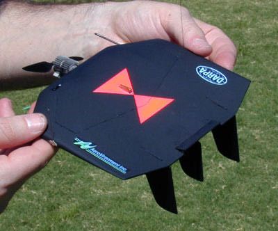
The vehicle aerodynamics model was validated by
     Multidisciplinary Design Optimization
                                                              performing wind tunnel tests on a variety of wing
The early prototypes demonstrated that a 6-inch aircraft      configurations. This allowed validation of the induced
was feasible. However, the MAV still required a video         drag and friction drag parts of the code. The
camera and an advanced control system that would              protuberance and interference drag components were
allow operation by an unskilled operator. Since the           then added individually.
prototype MAVs were clearly not capable of handling                The propeller aerodynamics model was validated
the extra weight and power of these additional systems,       by testing four different propellers in the wind tunnel
a more rigorous design approach was required to               over a range of velocities, airspeeds, and power levels.
continue evolving the system toward maturity.                 Both direct drive and geared props were tested.
      For this reason, a Multidisciplinary Design                  The motor model was validated by using the Solver
Optimization (MDO) methodology was developed in               in Excel to adjust the coefficients in the analytic motor
the summer of 1998 to maximize the performance of             model equations to minimize the error between the
the MAVs. The goal of the MDO methodology was to              model predictions and experimental performance
create a computer-simulated environment in which the          measurements over a range of shaft loads and power
optimum MAV configuration could evolve. The                   levels. Most of the motor models show less than 5%
simulated environment consists of physics-based               error from the experimental data.
models of the key aspects of the MAV design space, as              The battery model is simply a curve fit through
shown in Table 1. The design variables used for the           experimental discharge data at different power loads, so
first generation MAV optimization study are shown in          no validation was necessary.
Table 2. The objective function was to maximize the                Most of the early MAV prototype vehicles were
endurance of the MAV. In the MAV MDO code, the                flown with direct drive propellers. A few geared
optimization is performed by a genetic algorithm.             propeller configurations were built, but they had
         Table 1: Subsystem model descriptions                marginal performance. However, it was felt that the
                                                              geared prop concept still had enough potential to merit
Subsystem Model    Description                                further study for the first generation of the Black
Vehicle            Lifting line theory for induced drag,      Widow. Therefore two optimum configurations—a
aerodynamics       Blasius skin friction formulas for         direct drive prop and a geared prop—were created as
                   friction drag, Hoerner equations for       candidates for the final configuration.
                   interference drag, and equivalent               Even though the entire vehicle was optimized for
                   parasite areas for protuberance drag       each of the drivetrain types, the tip chords of both
                                                              configurations were roughly the same, and the loiter
Propeller          Minimum induced loss methodology
                                                              velocities were roughly the same. The optimizer also
aerodynamics
                                                              selected the same battery and the same motor for both
Motor              Analytic motor model with coefficients     configurations. Therefore these parameters were all
performance        adjusted to match experimental data for    frozen to the same values, to allow a normalized
                   each motor                                 comparison between the direct drive and geared
Battery            Curve fits of battery endurance vs.        propulsion systems. Table 3 shows the wing shape
performance        power draw based on experimental data      parameters, and Table 4 shows a comparison of the
Weight buildup     Mass budget of all fixed components,       direct drive and geared propulsion systems.
                   and simple weight equations for variable         Table 3: Wing shape parameters (common to
                   masses                                          both direct drive and geared prop designs)
               Table 2: MAV design variables                        Wing span                           6.0 in
                                                                    Wing centerline chord               5.4 in
        Design Variable           Range/Options
                                                                    Chord at spanwise breakpoint        5.4 in
        Battery type                   2                            Wing tip chord (in)                 3.9 in
        Motor type                     9                            Spanwise position of breakpoint     1.5 in
        Gearbox type                   4                            Wing thickness/chord ratio          8.4%
        Motor power draw             1-5 W
        Propeller diameter           2-4 in
        Wing tip chord               0-6 in
        Loiter velocity            20-40 mph

                                                          2
                                  American Institute of Aeronautics and Astronautics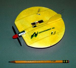
geared prop test results. The maximum attainable
       Table 4: Propulsion system parameters for
                                                             efficiency is constrained by the required thrust to be
  direct drive and geared propeller configurations
                                                             43%. The propeller wind tunnel tests have increased
                                  Geared       Direct        our confidence in the validity of the optimization code,
                                Prop (4:1)   Drive Prop      and they have shown that the direct drive propeller
  Required thrust                  9.9 g        9.4 g        configuration    outperforms      the    geared     prop
  Propeller diameter              3.81 in      2.67 in       configuration. Therefore we chose to use a direct drive
  Propeller RPM                    5,365       22,400        prop for the first generation Black Widow
  Propeller efficiency             80%          68%          configuration.
  Gearbox efficiency               81%          N/A              90%
  Motor RPM                       21,460       22,400            80%
  Motor efficiency                 62%          63%              70%          Propeller
  Total propulsion efficiency      40%          43%              60%
                                                                              Motor/Gearbox
  Power draw from batteries       4.65 W       4.35 W            50%
  Battery endurance              30.2 min     33.4 min           40%
                                                                 30%
                                                                 20%          Motor/Gearbox/Propeller
     The optimization code predicts that the endurance
of the geared prop configuration is 30.2 minutes, while          10%
the direct drive prop configuration has an endurance of           0%
                                                                       0             5         10       15         20   25
33.4 minutes. The direct drive prop configuration
                                                                                               Thrust (g)
achieves about 10% greater endurance than the geared
prop configuration. This is mainly due to the efficiency      Figure 2: Propeller, motor/gearbox, and combined
loss in the gearbox, the added weight of the gearbox,          efficiencies vs. thrust at 25 MPH for geared prop
and a larger and heavier propeller.
     In order to increase our confidence in this                90%
prediction, both propulsion systems were tested in the          80%
AeroVironment wind tunnel over a range of operating             70%          Propeller
conditions. Figure 2 shows the propeller efficiency,            60%
motor/gearbox efficiency, and the combined                      50%
                                                                                                               Motor
motor/gearbox/propeller efficiency vs. thrust at a              40%
freestream velocity of 25 MPH for the geared propeller          30%
configuration. The vehicle drag at 25 MPH (the                  20%          Motor/Propeller
optimum loiter velocity) is 9.9 g for the geared prop           10%
configuration. Therefore 9.9 g of thrust is required for         0%
level flight. Notice that the slopes of the propeller and              0            5          10       15         20   25
motor/gearbox efficiency curves are in opposite                                                Thrust (g)
directions near 10 g of thrust. Therefore the best total
                                                             Figure 3: Prop, motor, and combined efficiencies vs.
propulsion system efficiency is obtained by making the
                                                                   thrust at 25 MPH for direct drive prop
optimum tradeoff between the two efficiencies. Note
that the optimizer did this automatically, achieving a            Table 5 presents a performance summary for the
total propulsion system efficiency of 40%. Figure 2          first generation Black Widow configuration. Figure 4
shows the experimental data, which agrees well with          shows the mass breakdown.
the predicted performance shown in Table 4.
                                                                   Table 5: Performance summary for the first
     Figure 3 shows the propeller, motor, and combined
                                                                       generation Black Widow MAV
propeller/motor efficiencies vs. thrust at 25 MPH for
the direct drive prop. Since the direct drive                              Total mass                         56.5 g
configuration is slightly lighter than the geared prop                     Loiter drag                         9.4 g
configuration, it has less induced drag, and the required                  Lift/drag ratio                      6.0
thrust is 9.4 g. Notice that the propeller and motor                       Loiter velocity                   25 mph
efficiencies both decrease with increasing thrust at the                   Loiter lift coefficient             0.42
design point of 9.4 g. Therefore the combined                              Loiter throttle setting             70%
propulsion system efficiency does not have an                              Endurance                         33.4 min
unconstrained maximum at the design point like the

                                                          3
                                  American Institute of Aeronautics and Astronautics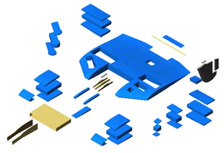
Payload                                                       Energy Storage
                  12%
                                                            In the beginning of the MAV program, we evaluated a
       Controls                                             wide range of power sources, including internal
         9%                                                 combustion engines, fuel cells, micro turbines, and
                                                            solar power, but the best source of energy among
                                                            currently available technologies turned out to be
                                                            modern lithium batteries. Fossil fuels have a much
     Structure
       17%                               Propulsion         higher energy density than batteries, but the currently
                                            62%             available small internal combustion engines are
                                                            extremely inefficient, difficult to throttle, and generally
                                                            quite unreliable. Small fuel cell technology looks
                                                            promising, but it is not here yet. Microturbines also
                                                            look promising, but they may take even longer to
 Figure 4: Mass breakdown for the first generation
                                                            mature. Solar cells cannot supply enough energy to
            Black Widow configuration
                                                            sustain level flight, but they could be used to recharge
                                                            the batteries while the MAV is parked somewhere.
     After arriving at the optimum configuration, a brief
                                                                 Batteries and electric motors are extremely reliable,
sensitivity analysis was performed. This analysis
                                                            inexpensive, and quiet. However there are tradeoffs
showed that an additional 1 gram of drag would
                                                            among different battery chemistries. Nickel-Cadmium
decrease the endurance by 3 minutes, and an additional
                                                            (NiCd) and Nickel-Metal-Hydride (NiMH) batteries
1 gram of mass would decrease the endurance by 30
                                                            have very high power densities, but very low energy
seconds.
                                                            densities. Lithium (Li) batteries are generally designed
     The first generation MAV configuration performed
                                                            to have high energy densities, but relatively low power
a 22-minute flight with a black and white video camera
                                                            densities. Also, NiCd and NiMH batteries are
on March 3, 1999. This vehicle weighed 56 grams, and
                                                            rechargeable, while most lithium batteries are not. We
had a cruise speed of 25 mph. The next step was to add
                                                            chose to use NiCd and NiMH batteries for flight testing,
color video and increase the endurance to our goal of 30
                                                            and lithium batteries for demonstration flights.
minutes. In the summer of 1999, we performed another
                                                                 As with any aircraft, the energy source is a primary
design iteration, and further refined the Black Widow
                                                            design driver. Therefore it is critical to have
design. The final vehicle is shown in Figure 5. The
                                                            quantitative data for many different batteries in order to
vehicle is controlled by a rudder on the central fin, and
                                                            select the best battery for the vehicle. During the MAV
a small elevator in the middle of the trailing edge. The
                                                            program, we characterized a variety of small batteries
pitot-static tube can be seen extending forward from the
                                                            using discharge tests over a range of temperatures. We
right wing tip.
                                                            reduced this data to a series of curve fits, and we used
                                                            the curve fits in the MAV optimization code.
                                                                                     Motors
                                                            Throughout the MAV program, we tested and evaluated
                                                            several electric motor candidates. We built a
                                                            dynamometer specifically for small motors, and we
                                                            tested each motor over a wide range of operating
                                                            conditions. The motor test data was used to create an
                                                            analytic math model of each motor. These motor
                                                            models were then integrated into the MDO code.
                                                                 The dynamometer tests showed that efficiencies as
                                                            high as 70% can be achieved with small motors. The
                                                            trends are that larger motors have higher efficiency to
                                                            power ratios, and higher voltage motors have higher
                                                            efficiency to power ratios. Unfortunately the motor
 Figure 5: Final Black Widow MAV configuration              voltage is limited by the battery supply voltage unless a
                                                            power converter is used.

                                                        4
                                American Institute of Aeronautics and Astronautics
available scales. The load cells have a 0.1-g accuracy,
Micro-Propeller Design
and they are insensitive to offset loads and moments.
The early MAV prototypes used plastic propellers
developed for small model airplanes. Some of these
propellers were modified by cutting and sanding
commercially available props. Since the propeller
performance is critical to the success of the MAV, we
developed a propeller design methodology which
allows us to significantly increase the efficiency of
small propellers.
The nominal mission profile for the Black Widow
is to climb to about 200 ft above ground level, and
cruise around at the optimum loiter velocity gathering
video data. Therefore at least 90% of the flight occurs
at a single flight condition. This greatly simplifies the
Figure 7: Upper half of propeller mold
propeller optimization, since the off-design conditions
do not strongly affect the overall performance. It also
allowed us to use the minimum induced loss propeller
design methodology to optimize the twist and chord
distribution for the loiter flight condition. The prop
diameter was optimized by the genetic algorithm along
with the other top-level vehicle design variables.
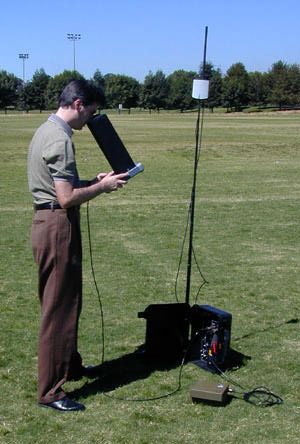
The propeller shown in Figure 6 was optimized for
a 4:1 gearbox and a 7-gram DC motor. The pitch is 6.04
inches, and the diameter is 3.81 inches.
Figure 8: Lower half of propeller mold
Figure 6: Micro-propeller designed for 4:1 gearbox
A 3-dimensional model of the propeller geometry
was created using the SolidWorks solid modeling
software. Stereolithography models of the upper and
lower mold halves were then created from the virtual
solid model. Figures 7 and 8 show the prop mold
geometry. The propeller was fabricated from
unidirectional and woven carbon-fiber composites.
To validate the propeller design code, a series of
tests were performed in the AeroVironment wind
tunnel. The wind tunnel is an open-circuit, suction
design with a test section that is 20 inches wide, 20
inches high, and 40 inches long. The tunnel is capable
of producing velocities between 5 and 80 mph in the
test section. The torque and thrust were measured using
the balance shown in Figure 9. This balance was
constructed using three load cells from commercially Figure 9: Balance for prop performance tests
5
American Institute of Aeronautics and AstronauticsFigure 10 shows the thrust vs. RPM and freestream Airframe Structural Design
velocity for the prop. The plot shows excellent
agreement between the experimental data and the code The structural design of an MAV presents several
predictions. The propeller was designed to produce 10 g unique challenges. Because of the square-cube law, the
of thrust at 25 MPH and 5,250 RPM. inertial loads induced on an MAV during accelerations
Figure 11 shows the propeller efficiency vs. RPM and decelerations (such as takeoff and landing) are
and velocity for the prop. The best measured efficiency quite small relative to larger aircraft. During a typical
was 83%, while the code predicted a peak efficiency of landing, the MAV flies into the ground at a shallow
82%. The propeller actually operates at 78% efficiency, angle and survives a few bounces with no damage. In
even though the peak efficiency at 25 MPH is 81%. fact, the worst case design loads for many parts of the
Since the motor efficiency is higher at higher speeds, a structure are the handling loads imposed by people.
slight sacrifice in propeller efficiency increased the The first generation Black Widow design used a
efficiency of the total propulsion system. Also note that solid foam wing structure with some internal
the peak efficiency increases with increasing freestream reinforcements in high-stress areas. The wing structure
velocity due to higher blade Reynolds numbers. consists of the basic wing, the internal rigid structure,
and the vertical fin assembly, as shown in Figure 12.
30
15 MPH
25 20 MPH
25 MPH
30 MPH
20 35 MPH
15 Data
20 Data
25 Data
15 30 Data
35 Data
10
5
0
2,500 3,000 3,500 4,000 4,500 5,000 5,500 6,000 6,500 7,000 7,500
Prop RPM
Figure 10: Thrust vs. RPM and freestream velocity
for 3.81-inch diameter propeller Figure 12: Solid foam wing structure
The wings are fabricated from expanded
90%
polystyrene (EPS) foam. The foam has many desirable
80% 15 MPH
20 MPH qualities, including ease of shaping, light weight,
25 MPH
70% 30 MPH
strength, and ease of bonding.
60%
35 MPH
15 Data
The main pieces in Figure 12 are shaped by cutting
20 Data
25 Data
using a hot wire tool. The ends of the wire are moved
50%
30 Data
35 Data
by CNC-controlled stepper motors, such that precision
40%
cuts can be made from CAD drawings.
30% A cavity is cut from the leading edge of the center
20% wing section. This is the area where the internal rigid
10%
structure is embedded. The internal rigid structure is
designed to hold the most massive parts of the MAV,
0%
2,500 3,000 3,500 4,000 4,500 5,000 5,500 6,000 6,500 7,000 7,500 (batteries and motor) together, and tie into the high load
Prop RPM
points of the MAV, such as the launch lug. The rigid
structure is mainly fabricated from fiberglass sheet.
Figure 11: Efficiency vs. RPM and freestream The vertical fin assembly is hand fabricated from
velocity for 3.81-inch diameter propeller balsa wood. The rudder is also made of balsa wood and
is hinged with Kevlar cloth.
6
American Institute of Aeronautics and Astronauticsvideo stream as an input, modulates it using frequency
Avionics
modulation (FM), and outputs it as a RF signal. 2.4
One of the objectives for the Black Widow MAV is to GHz was used because commercial video receivers and
achieve autonomous flight so that the vehicle can be antennas are readily available. The first generation
easily operated by an unskilled operator. The first step COTS video transmitter had moderate performance
toward autonomous flight is to sense the state of the because of low power conversion efficiency in the RF
vehicle and pass the data to the flight computer. For this amplifier section. For the final MAV system, an
reason, the Black Widow has a two-axis magnetometer improved transmitter with higher output power, smaller
to sense compass heading. A pitot-static tube is size, and lighter weight was developed.
connected to an absolute pressure sensor to sense
altitude and a differential pressure sensor to sense Table 6: CMOS video camera specifications
dynamic pressure. The vehicle also uses a piezoelectric
Black & White Color
gyro to sense the turn rate.
Mass (g) 2.2 1.7
The MAV must also receive commands from the
Power (mW) 50 150
ground station, and translate the commands into control
Resolution 320 x 240 510 x 488
surface movements and throttle changes. This requires a
(pixels)
command uplink receiver, a flight computer, and
control actuators. The uplink receiver has a mass of 2
Table 7: Video downlink transmitter specifications
grams, and is about the size of two postage stamps. It
operates at 433 MHz. The aircraft uses two First Generation Final
microprocessors to perform onboard computations. The Mass (g) 3.3 1.4
rudder and elevator control surfaces are moved with Power Input (mW) 550 550
custom-developed 0.5-gram actuators. Power Output (mW) 50 100
Video Camera Payload Frequency (GHz) 2.4 2.4
The Black Widow MAV was developed as a platform Stability and Control
to deliver live color video images in real time to an
observer on the ground. The video payload evolved The small size of an MAV creates several unique
from a current off-the-shelf (COTS) video transmitter, stability and control challenges. Since the mass moment
and a modified COTS black and white CMOS camera, of inertia scales as the fifth power of the characteristic
to a custom video transmitter and a custom color dimension, small vehicles tend to have high natural
CMOS camera, as shown in Figure 13. frequencies of rotational oscillation. Obtaining a stable
video image requires an actively stabilized camera
mount or an actively stabilized aircraft. Therefore high
oscillation frequencies require a control system with
fast processors and fast actuators to stabilize the camera
or the entire MAV. Since wing loading decreases with
decreasing size, small air vehicles are quite susceptible
to gusts. Even small birds (with highly evolved active
control systems) have trouble maintaining steady flight
in extremely turbulent conditions.
Figure 13: Black & white camera, COTS The main stability augmentation system used on
transmitter (top); custom color camera, the MAV is a yaw damper. Many of the early prototype
custom transmitter (bottom) MAVs showed a 3 Hz Dutch roll oscillation. The
addition of more vertical tails and the yaw damper
There are a wide variety of micro video cameras on
significantly increased the damping ratio. The MAV
the market today. The challenge for an MAV is to find
has three autopilot modes: dynamic pressure hold,
a good balance of high image quality, low weight, low
altitude hold, and heading hold. More autopilot modes
power, and small size. We found a good compromise
may be added in the future as the system becomes more
with the CMOS video cameras. Table 6 shows the
advanced, and as new sensors, such as a GPS receiver,
specifications for the CMOS cameras used on the Black
are added. We also developed a data logging system
Widow.
which can sample 16 channels of data at 20 Hz for 4
To get the video from the onboard camera to the
minutes. This was used to evaluate and refine the
ground, we used a radio frequency (RF) transmitter
control system dynamics.
operating at 2.4 GHz. The transmitter takes the analog
7
American Institute of Aeronautics and AstronauticsPerformance Ground Control Unit
On August 10, 2000 the Black Widow MAV performed In addition to the MAV itself, a fully functional MAV
a flight which most likely established several world system requires a user-friendly, rugged, and compact
records for the MAV class of aircraft. Table 8 ground control unit (GCU). The Black Widow GCU
summarizes the performance on this flight. The pilot evolved through three stages to reach its final form. the
flew about 90% of the flight "heads-down," which first generation GCU was a collection of off-the-shelf
means he was looking only at the video image and equipment which was quite bulky, and had to be
downlinked sensor data from the MAV. assembled at the field. The second generation GCU was
a 15-lb briefcase that contained the MAV, a pneumatic
Table 8: Performance summary for the Black
launcher, a removable pilot's control unit with a 4-inch
Widow flight on August 10, 2000
LCD display for the downlinked video, and an
Endurance 30 min automatic tracking antenna. The final GCU (Figure 14)
Maximum Range 1.8 km is built around a Pelican case, which is extremely
Maximum Altitude 769 ft rugged, compact, and waterproof. The MAV is stored
Mass 80 g in a separate cassette box, which also serves as the
launcher. To fly an MAV, the user simply connects the
GCU to the launch cassette with a cord, aims the box to
Since the Black Widow uses an electric propulsion
the sky, and presses the launch button on the pilot's
system, it is extremely difficult to observe in the air. It
controller.
cannot be heard above ambient noise at 100 ft, and
unless you're specifically looking for a 6-inch square Conclusions
black dot in the sky directly overhead, you can't see it. The Black Widow MAV program has been quite
It looks more like a bird than an airplane. In fact, we successful in proving that a 6-inch aircraft is not only
have seen sparrows and seagulls flocking around the feasible, but that it can perform useful missions that
MAV several times. were previously deemed impossible. Additionally, the
Micro Air Vehicle concept has opened the doors to
many new avenues of research in the fields of
aerodynamics, propulsion, stability and control,
multidisciplinary design optimization, microelectronics,
and artificial intelligence. Some of the specific
conclusions resulting from the Black Widow
development are:
• A direct drive propulsion system appears to be
more efficient than a geared propulsion system
at the MAV scale.
• Propeller efficiencies of 80% or greater are
possible at the MAV scale.
• Motor efficiencies of 70% or greater are
possible at the MAV scale.
• An electric propulsion system appears to be
the simplest, cheapest, stealthiest, and most
reliable option with today's technology.
• The Multidisciplinary Design Optimization
methodology is essential to maximize the
efficiency of the entire MAV propulsion
system.
Figure 14: Black Widow ground control unit and • The propulsion system efficiency is the key
cassette launcher shown deployed (above) and parameter in maximizing the endurance of an
stowed (below) MAV.
8
American Institute of Aeronautics and Astronautics• Since the structural weight of an MAV does
not vary significantly with configuration
variations, the structures subsystem is weakly
coupled to the other aircraft subsystems at the
MAV scale.
• It is possible to build a basic avionics suite
with data logging capability at the MAV scale.
• A color video camera with downlink
transmitter can be built with a mass of about 3
grams using current technology.
• A 6-inch span, electric MAV is capable of
downlinking live color video from a range of
1.8 km, with an endurance of 30 minutes, and
a vehicle mass of 80 grams.
Acknowledgments
This work was supported by the DARPA Tactical
Technology Office, under contract DAAH01-98-C-
R084. The authors would like to express thanks to the
rest of the Micro Air Vehicle team at AeroVironment
for their tremendous contributions to this project. The
team includes Alex Andriukov, Ken Carbine, Craig
Foxgord, Dave Ganzer, Mark Levoe, Les Littlefield,
Scott Newbern, Stuart Sechrist, and Carrie Sundra.
References
1 Hundley, Richard O., and Gritton, Eugene C.,
"Future Technology-Driven Revolutions in
Military Operations," RAND Corporation,
Document No. DB-110-ARPA, 1994.
2 Davis, W.R., "Micro UAV," Presentation to 23rd
AUVSI Symposium, July 15-19, 1996.
9
American Institute of Aeronautics and AstronauticsYou can also read