INSTALLATION & OPERATION MANUAL - SS395 Sonar - August 2012 WESTERN MARINE ELECTRONICS
←
→
Page content transcription
If your browser does not render page correctly, please read the page content below
SS395 Sonar
 INSTALLATION &
OPERATION MANUAL

            August 2012

          WESTERN MARINE ELECTRONICS
          14120 NE 200th Street, PO Box 7201
           Woodinville, WA 98072-4001 USA
   Telephone: (425) 481-2296 Fax: (425) 486-0909
  Email: dsoderberg@wesmar.com www.wesmar.com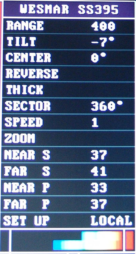
Part 1:
Sonar Controls
1.1 Hand Control
All sonar adjustments are conducted
through the hand control.
1.1.1 Trigger Switch
The trigger switch will move the cursor from
the sonar screen to the selection screen when
adjustments are needed. After adjusting, the trig-
ger switch will return the cursor back to the sonar
screen.
1.1.2 Four-way Control Switch
The four-way control switch will move the cursor
up/down, left/right on the sonar screen. By placing
the cursor on a target both horizontal and vertical
measurements are logged in the space noted by the
arrows, center right of screen.When the cursor is
in the selection screen the four-way switch will
move the cursor up/down to the item for adjust-
ment. Moving the four-way switch left/right will
make the change.
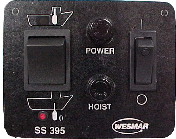
1.2 Switch Panel
Both the sonar and the hoist are independent
of one another. The sonar has its own on/
off switch and the hoist has its own down/
up switch.
2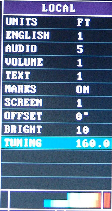
1.2.1 Sonar On/Off Switch
The sonar on/off switch is fused with a 10
amp slow blow (MDL) fuse. This fuse is
inline with a fuse on the power supply board
inside the computer box. The power supply
fuse is 7.5 amp fast blow (AGC) for 12 or
24 volt operation.

       1.2.2 Hoist Down/Up
To lower the hoist push down on the hoist switch.
If the hoist is hydraulic a green light will glow
                                                       Lead Screw Hoist
when the motor is running and turn off when the
motor stops. The green light is not used with the
lead screw hoist systems. On all systems a red light
will stay on as long as the hoist is down.

       1.2.3 Hoist Fuse
On lead screw hoist systems the fuse used is MDL
(slow blow) 3.2 amp. On hydraulic systems use
AGC (fast blow) 1 amp. If the fuse is open the
hoist will not go down.

1.3 Selection Screens                                   Hydraulic Hoist
There are four selection screens where adjustments
are made. Each adjustment can be viewed as the
sonar runs to maximize target detection. The four
selection screens are titled as; Wesmar 395, Sonar,
Profiler and Local. To make an adjustment to the
sonar, trigger once with the hand controller. This
will activate the Wesmar 395 selection screen. To
enter any of the other three selection screens push
up or down on the four way switch until SET UP
is highlighted. Push left or right on the four way
switch for: S = Sonar, P = Profiler, L = Local then
trigger with the hand controller. After adjustments
are made, trigger the hand controller to move the
cursor back to the sonar screen.

       1.3.1 Wesmar 395 Selection Screen
Wesmar 395 is the first screen to appear when
triggered with the hand controller. All of the
adjustments are for sonar with the exception of
NEAR P and FAR P, which are gain adjustments
for profile.
                                                                          3
RANGE
Sonar range can be increased or decreased by push-
ing the four-way switch on the hand controller to
the left or right. Range units; meter, fathom, feet
are selected in selection screen Local.

TILT
Transducer can tilt up +4 degrees above the hori-
zontal to –90 degrees straight down. A 0 degree tilt
will center the sound beam horizontally.

CENTER
Move the sector in nine-degree steps around the
screen.

REVERSE
Reverse will change the direction of scan. This
is the recommended method when following fast
moving tagets such as tuna and game fish. There
are two ways to reverse scan.
1. Highlight reverse, push the four-way switch to
the left or right. Each time the four-way switch is
pushed scan will reverse.
2. Highlight reverse, pull the trigger to reverse scan.
Pull the trigger again to highlight reverse then pull
the trigger to reverse. As fast as one can pull the
trigger two times the scan will reverse.

THICK
Thickness will work in sonar screen #1 only. Thick-
ness is scanning up and down through the target
or over the bottom. This is an excellent way to see
if there are more fish under the fish schools that
were scanned in the horizontal or to determine the
vertical size distribution of the school. Thickness
can also be used to profile the bottom out in front
to measure depth when entering uncharted
waters.

There are two ways to activate thickness.
1. Highlight thick. Wait for the horizontal scan
to pass through the target. Pull the trigger, the
transducer will stop and start to scan up and down
through the target. The vertical display will show
in the lower right of the screen. As the target

4
moves the thickness mode of operation can
move to follow the target by pushing the four-way
switch to the left or right. Reverse can also be used
to change direction of the vertical scan. To end the
thickness mode pull the trigger twice.
2. Highlight thick. Push the four-way switch to
the left or right. The transducer will stop and start
to scan up and down. Push the four-way switch a
second time to end thickness mode. Note: Entering
thickness mode by using the four-way switch will
disable the ability to change bearing. Bearing can
only be changed when entering thickness by using
the trigger switch.

SECTOR
Select the area to be scanned from full circle; 360
degrees down to 11 degrees.

SPEED
Controls the scanning speed of the sound beam.
Speed 1 is for fine resolution. Speed 4 is for fast up-
date. Faster speeds may lose single fish targets.

ZOOM
 In Screens 1, 2 and 3 the cursor can be used as
a magnifier. By activating zoom the target under
the cursor will magnify for a close inspection.
The perimeter line around the cursor indicates the
magnified area.

NEAR S
Near gain adjustment for sonar. Gain numbers run
from 0 to 100. Regardless of range the near gain
has more control over targets from the center of
the screen to half way out. Adjust for best presen-
tation.

FAR S
Far gain adjustment for sonar. Gain numbers run
from 0 to 100. Regardless of range the far gain has
more control over targets from half way to the end
of screen range, or the last half of range selected.
Adjust for best presentation.

NEAR P
Near gain adjustment for profile. Profile gains are
separate from sonar. Gain numbers run from 0 to
                                                          5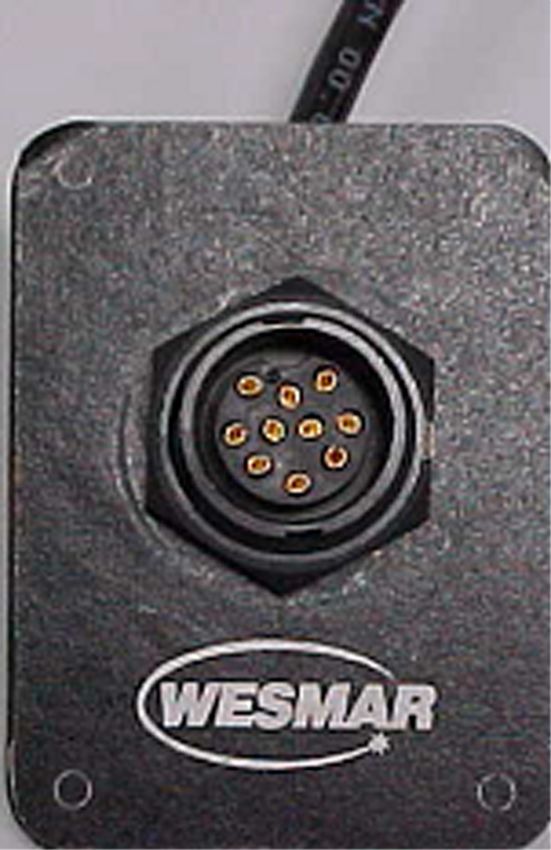
100. Regardless of range the near gain has more
control over targets from the center of the screen
to half way out. Adjust for best presentation.
FAR P
Far gain adjustment for profile. Gain numbers run
from 0 to 100. Regardless of range the far gain
has more control over targets half way to the end
of the screen range. Profile is frequently used to
profile the bottom. FAR P adjustment is used to
bring bottom markings in strong.
SET UP
Set up provides access to three other selection
screens; SONAR, PROFILE, LOCAL. To acti-
vate one of the three screens first trigger the hand
controller once. The WESMAR 395 screen will
appear. Move the four-way switch up or down to
set up. Push the four way switch left or right to
highlight the selection screen you want to go to.
Trigger the hand controller for the second time to
view the screen.
By triggering the hand controller the third time will
place the cursor back into the sonar display.
COLOR BARS
There are two color bars, one on top of the other.
The top color bar represents the colors and thresh-
old for sonar. The bottom bar represents the colors
and threshold for profile. Adjustments are found in
SONAR and PROFILE.
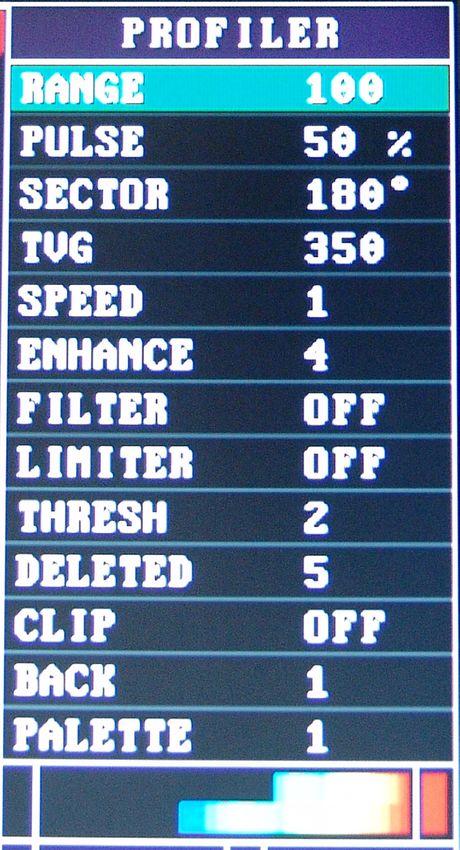
1.3.2 SONAR
Sonar refers to horizontal scan around the vessel.
This is different from profile where the transducer
scans from side to side beneath the vessel. To
maximize target detection both sonar and profile
each have their own selection screen. Adjustments
can be different from the other. The SS395 will
store the settings and recall them the next time the
system is turned on. However, if there is more than
one application (more then one fishery) a record of
the settings should be kept.
RANGE
Same range adjustment under Wesmar 395. For
6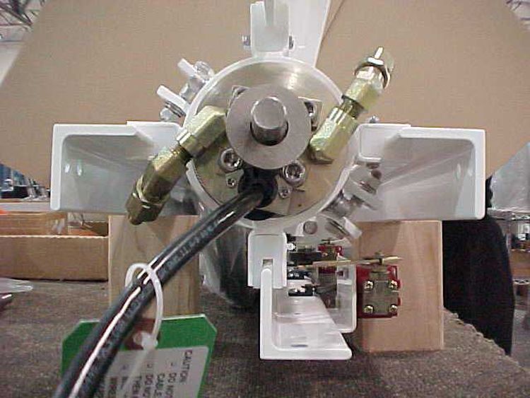
convenience sonar range is repeated.

PULSE
Pulse refers to the transmit pulse or the time the
transmitter is on pushing sound energy into the
water. A long pulse, 100% is best for long-range
detection. Selecting shorter pulse lengths will
increase range resolution separating two targets
close together. As the pulse length is shortened,
near and far gains will need to be increased.

SECTOR
Same sector adjustment found in the last selection
screen, Wesmar 395. For convenience sector is
repeated.

TVG
Time Variable Gain offsets propagation loss as
sound energy moves through the water. A target
at long range will have a small echo than close
to the vessel. In order for this target to mark the
same color at different ranges the receive gain must
increase proportionally with range. Propagation
losses of sound energy will change with frequency,
salinity, and the amount of plankton and algae in
the water. Adjust TVG according to the frequency
of the sonar.

 Adjustment:
160kHz set TVG to 400,
span 200 to 600
110kHz set TVG to 600,
span 400 to 800
 60kHz set TVG to 800,
span 600 to 1000

Each 100 units will equal 250 ft or 75 meters of
range. A setting of 400 will then equal 1000 ft or
300 meters. When using the blue background a
gray ring will display on the screen equal to the
TVG setting. Targets on the inside of the ring will
be compensated for propagation losses where
targets outside the ring will become stronger as
the vessel approaches until the target cross over
the gray ring.

SPEED
                                                       7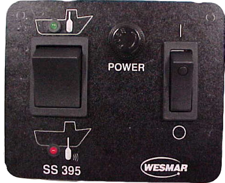
Speed will change the scanning speed of the trans-
ducer. A speed of one will step the transducer in
1.8 degree steps, where a speed of four will step
in 7.2 degree steps. A speed of one is considered
regular scan with fine resolution where a speed of
four yields a faster scan with lower resolution.

ENHANCE
Enhance is one of three filters. Selections are
from OFF to 5. Enhance will help in target recog-
nition of individual targets such as tuna, salmon,
and sports fish. If bottom typing for shrimp, turn
enhance off.

FILTER
Filter is the second of three filters. Filter is used to
filter out unwanted returns and reduce clutter from
the screen. Filter should be turned off when scan-
ning for small targets. Use Filter when scanning
for schools of fish and bottom typing

LIMITER
The third of the three filters. The limiter can be ON
or OFF. When ON, interference from any other
sonar/sounder equipment on board will not mark
on the screen. This is accomplished by eliminating
all targets that are not present in two consecutive
transmits at the same range. The limiter is very
effective; however, when scanning for individual
targets it is recommend to turn the limiter OFF.
When the limiter is ON there will be a (?) after
ON to question the operator if this is the correct
setting.

THRESH
Or Threshold. Selections are from 1 to 4. In order
for a target to display on the screen, the echo, after
going through the receiver, must be strong enough
to reach the colors. The colors can be raised or
lowered. Lowering the threshold will display all
targets including weak ones without adjusting
gains. Raising the threshold will remove weak
targets leaving only strong targets on the display.

DELETE
Delete will remove targets colors weak to strong.

8

CLIP
Clip is a color stronger then red. Clip is primarily
used for bottom typing to distinguish between,
rock, sand, or muddy bottom. On hard bottom ad-
just gains so bottom just marks in the clip color.

BACK
Back or background is the color behind the targets
on the screen. 1=Black, 2=Blue and 3=White.

Black can be used at night and during the day. At
night the black background emits no light and the
targets stand out in fine detail. For nighttime view-
ing it is recommended to lower the brightness of
the text or words on the right of the screen. To dim
the text go to the LOCAL page and increase the
number for TEXT. Blue and White are normally
day time screen. A background color will increase
the contrast making the target much easier to view.
If small targets are of interest try the white back-
ground and select 4 to 6 on PALETTE.

PALETTE
Palette deals with target color brightness from blue
to red. When using a low threshold the screen
may by full of blue and green targets. Too much
color on the screen may be distracting; however,
the weak targets are telling the operator something
about the area of search. Palette is a brightness
scale that will dim target colors from weak to
strong. Select a palette number that will dim the
weaker targets without removing them from the
screen. This helps in strong target recognition with
less fatigue to the operator.

        1.3.3 PROFILE
Profile scans the transducer from side-to-side un-
der the vessel like a pendulum of a clock. Profile
expands bottom coverage not covered by down
sounders. Because the sound beam is narrow
resolution off the bottom is very good. The SS395
in profile will cover the bottom six times that of
a down sounder without the loss of resolution.
To optimize detection profile has its own adjust-
ments.

                                                        9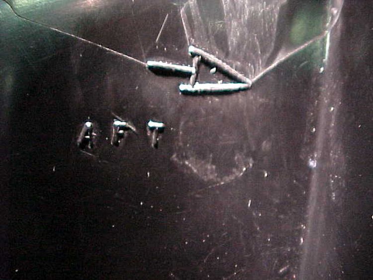
When operating in split screen, SONAR settings
are used when scanning horizontal. When the
transducer moves to profile the PROFILER set-
tings will be used.

RANGE
When profiling the bottom select a range equal to
twice the depth. This will give full bottom coverage
across the screen.

PULSE
A long transmit pulse, 100% will deliver more
power into the water then a short pulse. A short
pulse has superior range resolution then a long
pulse. When profiling for fish just off the bottom
a short pulse should be selected. As the pulse
length is shortened, near and far gains will need
to be increased.

SECTOR
Profile has its own sector sizes with the center mark
straight down.

TVG
Time Variable Gain offsets propagation losses
as sound energy moves through the water. These
losses are compensated by the TVG setting. Losses
are different with different frequencies.

Adjustment:
160kHz set TVG to 300, span 200 to 600
110kHz set TVG to 500, span 400 to 800
 60kHz set TVG to 700, span 600 to 1000

SPEED
Speed will change the scanning rate of the trans-
ducer as it sweeps over the bottom. For good bot-
tom detail use speed 1.

ENHANCE
Enhance is one of three filters. Enhance will help
in target detection of fish and objects on the bottom
small in size.

FILTER
Filter is the second of three filters. Filter is used to
reduce clutter; however, too much filter will lower
10
the probability of detection of small targets.

LIMITER

The third of three filters. The limiter can be ON or
·OFF. Turning ON the limiter will remove inter-
 ference from other sonar/sounder equipment from
 the screen. Objects close to the bottom or on the
 bottom may not mark with the limiter ON. The
 limiter should only be used when large targets are
 of interest.

THRESH
Or threshold. Selections are from 1 to 4. If set
too high, only strong targets will be detected. If
the threshold is set low the smallest of echoes will
be detected. For bottom typing a low threshold
setting is desirable.

DELETE
Delete will remove targets colors weak to strong.

CLIP
Clip is a color stronger then red when selected.
When bottom typing make the following settings.
Select the clip color. Lower the threshold to 1.
Turn ENHANCE to OFF. Turn FILTER to 5. When
over hard bottom adjust the near and far gains so
the bottom just marks in the clip color. All other
bottom types will mark in cooler colors.

BACK
Back or background is the color behind the targets
on the screen. 1=Black, 2=Blue and 3=White.

Black can be used at night and during the day. At
night the black background emits no light and the
targets stand out in fine detail. For nighttime view-
ing it is recommended to lower the brightness of
the text or words on the right of the screen. To dim
the text go to the LOCAL page and increase the
number for TEXT. Blue and White are normally
day time screen. A background color will increase
the contrast making the target much easier to view.
If small targets are of interest try the white back-
ground and select 4 to 6 on PALETTE.

                                                        11
PALETTE
Palette is a target brightness control. When ac-
tivated screen targets will dim from blue to red.
When using lower thresholds 1 or 2 the screen may
be cluttered with targets. Rather then deleting the
lower colors use PALETTE to lower the brightness
of the weaker targets.
1.3.4 LOCAL
Local are general adjustments that are not changed
to often.
UNITS
Select; feet, meters or fathoms.
LANGUAGE
Select the number that corresponds to the language
of preference.
AUDIO
The hand controller has a built in speaker that will
sound when targets are displayed on thescreen.
For additional volume connect an external ampli-
fied speaker to the audio line output jack on the
computer control unit, see section 3.1.6 for more
information. Audio is only activated after the first
range ring. This will reduce any audio from noise
that is around the boat. Audio is extended to the
corner of the screen. Two types of audio are avail-
able; Fish Alert and Modulation.
FISH ALERT
Fish alert is ideal for purse seining. When fish
schools mark on the screen the alert will sound.
Fish alert is only sensitive to the clip color. Colors
other then clip will not trigger the fish alert. The
size of schools that triggers the alert is determined
by selecting 1 for small schools and 10 for larger
schools. OFF will turn the fish alert off.
MODULATION
Modulation will sound on any size of fish target
and or bottom. By deleting colors or changing
thresholds the sound will follow the change. There
are three selections of the modulation sound, M-1,
M-2 and M-3. Both M-1 and M-2 will have the
sound of the transmit pulse at the beginning ofthe receive cycle. Modulation M-1 has a louder transmit sound then M-2. Modulation M-3 has no transmit sound, only the fish target will sound and or bottom will be heard. VOLUME Speaker volume selected from 1 to 5. TEXT Text will dim all the white lettering and range rings for night time viewing. MARKS Range rings can be turned on or off. SCREEN There are four fishing sonar screens available. Screen #1: Full circle sonar Screen #2: Split Screen sonar on top with bottom profile on bottom. Screen #3: Half screen bottom profile only. Can run with the soundome in the up position Screen #4: Full screen down sounder. (Note: Sounder controls Down Sounder settings.) BRIGHT Brightness will control the overall intensity of the display. TUNING Adjust frequency for the best target presentation with minimal noise. This adjustment changes the frequency of the transmitter and receiver. ADJUSTMENT: 160kHz, set to 159kHz: span 156kHz to 162kHz. 110kHz, set to 114kHz: span 108kHz to 117kHz. 60kHz, set to 60 kHz: span 57 to 62kHz. UPDATE When new programs come available the software can be installed in the sonar computer board. Select UPDATE to transfer the new program to the trans- mit receive motor drive board no the hoist assembly. Can be used to restore the program if need be. 13
Part 2:
      Installation
        2.1 Wheelhouse
           Equipment

  Check List:
  Hand Controller: Part # 64.10342.0
  Bulkhead Connector: Part 		                         Hand Controller
  #78.10389.0
  Computer Control Unit: 110VAC
  Part #64.09607.0, 220VAC Part
		      #64.09607.1
  Switch Panel: SP395DC
  Part #64.01395.0, SP395H
  Part #64.02395.0
  Monitor
                                                      Expansion Box
       2.1.1 Hand Controller
The SS395 hand controller can be considered the
sonar consolate where all adjustments are made.
Its location should be easily reached when fishing.
The hand controller has a 10ft, 3.0 meter cord with
a connector at the end that mates to the bulkhead
connect.

Would you like to have more than one hand con-
troller? Three good locations would be the wheel
house, flying bridge and/or the fish deck. By in-
stalling the hand controller expansion box, part
#64.00342.0, and three bulk head connectors part
#64.10342.0 this will give you full sonar control
from three locations.

       2.1.2 Bulkhead Connector Panel
The bulkhead connector panel comes with a 10ft
(3 meter) cable with a connector at the end. This     Bulkhead Connector
connector will mate to the computer control unit or
expansion box. To install the bulkhead connector,
14                                                                         14
make a hole in the instrument panel 1 3/4 inches
(44.5 mm) in diameter. Attach the bulkhead con-
nector plate to the instrument pnael using the holes
in the four corners.
2.1.3 Computer Control Unit
The computer control unit is designed to fit under
the instrument panel. There are three cables in the
wheelhouse that connect to the computer control
unit. Consider the length of these cables before
selecting a lcoation to mount the computer control
unit.
1. The cable from the bulkhead connector panel is Computer Control
10ft ( 3 meters) long. it must reach the computer
control unit.
2. The AC power cable from the switch panel is
6 ft (1.8 meters) long. It must reach the computer
control unit.
3. The monitor video cable on most monitors is
normally short. Use an extension VGA cable to
reach the computer control unit if needed. (Exten-
sion cable not supplied).
Fasten the computer control unit in place using the
holes in the mounting plate.
Lead Screw Hoist
2.1.4 Switch Panel
There are two switch panel assemblies, one for
a lead screw hoist and the other for a hydraulic
hoist. Installation is the same for both. The switch
panel does not need to be next to the bulkhead
connector.
Switch panels for both the hydraulic hoist and the
lead screw hoist are the same size. They provide
power to the computer control unit through a 6ft
(1.8 meter) cable. This cable must reach the com-
puter control unit. Make a hole 2.5 X 2.5 inches
(63.5 X 63.5 mm). Pass the wires through the Hydraulic Hoist
hole and attach the plate by the four corners to the
instrument panel.
2.1.5 Monitor
Specifications:
1. VGA, 640 X 480
2. Horizontal Sync. 31.5 kHz
153. Vertical Sync. 60 Hz
4. Flat Screen or Tube type. Any size.
When selecting a location, keep in mind the fol-
lowing:
1. Select a location where the monitor is in full
view when fishing.
2. What voltage is available in the wheelhouse to
run the monitor? A converter may be needed to
supply the correct voltage.
3. If there is a chance the monitor might get wet,
install a splash proof or waterproof monitor.
4. If the monitor is in direct sunlight, install a sun-
light viewable monitor.
5. If the monitor will be flush mounted, select a
monitor with the on/off and adjustment controls
are on the front.
6. Most monitors come with cables. The video
cable is typically 5 ft (1.5 meters) long. The video
cable connects to the computer control unit. If the
video cable is not long enough use a standard VGA
extension cable.
2.1.6 Audio Line Output
Below the VGA connector on the computer control
unit is a mini jack. This jack will supply the audio
line voltage to an external amplifier that is con-
nected to the speaker. Speakers with amplifiers are
the type used as external speakers on computers.
The mini jack on the SS395 is compatible with the
computer type speakers.
WARNING: Do not connect speakers directly.
In doing so, the audio circuit will be damaged,
not covered by warranty. Only use speakers
with built in amplifier like the type used on
computers.
2.2 Seachest
Installation
Checklist:
How much room is needed?
Seachest location.
Seachest Specifications.
162.2.1 How much room is needed?
There are three measurements needed to determine
the vertical height of the hull unit, seachest and
hoist assembly together.
1. Depth of keel at the location of the seachest.
The overall vertical height is the total length
of the seachest plus the hoist assembly on top. If
the boat has a keel then part of the seachest will
pass through the hull to the bottom of the keel.
This distance will reduce the vertical height needed
inside the boat.
2. Seachest length.
The seachest must be long enough for the
soundom to fit inside plus 1 1/2 (38mm) for protec-
tion when not in use. This becomes the minimum
length. the minimum length is different for the
following models:
Model: Minimum Length
SS395-E-160 21 in (53.3 cm)
SS395-H-160 24 in (61 cm)
SS395-E-110 22.5 in (57.2 cm)
SS395-H-110 25.5 in (67.8 cm)
SS395-E-60 22.5 in (57.2 cm)
SS395-H-60 29.5 in (74.9 cm)
3. Hoist length
The vertical length is different for the fol-
lowing models:
Model: Minimum Length
SS395-E-160 25.75 in (65.5 cm)
SS395-H-160 33 in (83.8 cm)
SS395-E-110 28.75 in (73 cm)
SS395-H-110 33 in (83.8 cm)
SS395-E-60 28.75 in (73 cm)
SS395-H-60 33 in (83.8 cm)
2.2.2 Seachest Location
For the best sonar performance avoid items in
front of the seachest that can create bubbles or
turbulence. Items such as zinc plates, cooling pipes,
sounder housings, water intakes or discharge ports
should NOT be in front of the seachest.
17Avoid installing the seachest near other sounding
equipment. Down sounders should be behind the
seachest. Other sonars should be on the opposite
side of the keel.
Select a location 1/3 to 1/2 of the ship’s overall
length back from the bow. On lighter boats where
the bow is likely to come out of the water at times,
moving the seachest closer to the half length is
recommended.
Athwart Vessel Location:
1. Installation through the keel is optimum,
center line of vessel roll.
2. Along side the keel and 1/2 in (13 mm)
up from the keel is a very good location, vessel
roll is minimal. The keel also adds strength to the
seachest as it protrudes through the hull. Fair the
seachest to the keel. Alongside the keel will help
keep debris from snagging.
3. If next to the keep is impossible, locate
the seachest within 40 in (1 meter) from the keel.
The bottom of the seachest must extend down to
1/2 in (33mm) up from the keel. Fair the seachest
for-and-aft but not to the hull. If faired to the hull,
bubbles will travel down the taper to the soundome.
To deflect debris a plate cut at a 45 degree angle
to the hull should be attached to the leading and
trailing edge of the fairing. The plate will deflect
debris and not catch on the seachest.
2.2.3 Seachest Specifications
The SS395, depending on the model, will have a 6
in soundome or an 8 in soundome. The size of the
soundome will determine the pipe and the flange
specifications. Use one of the following drawings
when fabricating the seachest at the boat yard.
Steelaluminum.
use and woodenFiberglass
boats use steel.
boatsAluminum boats
use fiberglass.
Fiberglass seachest with flange can be ordered
from WESMAR. (6 in part #62.04327.0 or 8 in
part #62.04329.0)
6-inch Seachest
1. Use 6-inch schedule 80 steel pipe
(5.761 Id nominal)
2. Length between minimum length (3.2.1)
and 40 in (1.2 m)
183. Paint inside with same bottom paint as hull.
8-inch seachest
1. use 8-inch Schedule 80 steel pipe
(7.625 in ID nominal)
2. Length between minimum (3.2.1)
and 40 in (1.2 m)
3. Paint inside with same bottom paint as hull.
2.3 Electrical Hoist
Installation
Note: The SS395 can be ordered with an electrical
hoist or a hydraulic hoist. Section 3.3 will cover
the electrical hoist with 3.6 will cover the hydraulic
hoist.
Checlist:
Calculate the length of the
soundome tube
Check soundome clearance
inside seachest
Fasten the soundome to the
soundome tube
Assemble hoist
Attach hoist to seachest
2.3.1 Calculate Lenth Of Soundome
Tube
There are two electrical hoist systems. One for the
6 in soundome and another for the 8 in soundome.
The difference between the two is the size of the
flange and the total travel.
1. 6 in soundome: measure the length of the
seachest and add 4 in (10 cm)
2. 8 in soundome: measure the length of the
seachest and add 5.5 in (14 cm)
When the proper length of the soundome tube is
determined, measure from the threaded end, mark
the length and cut. File the rough edges.
2.3.2 Check soundome clearance in
side seachest
The soundome should not fit tight inside the
19seachest. This can place addition strain on the
hoist motor and damage it. Also, if the insides of
the seachest start to rust the dome may jam and
possible damage to the hoist motor may be the
result. A loose fitting soundome will be subject to
vibration reducing sonar performance.
The SS395 soundome must fit the seachest with a
clearance no greater than 1/16 in (1.6 mm). Both
the 6 in and 8 in ABS soundomes have fins or ribs
on the side of the dome. The fins can be filed down
for the correct fit.
When checking the soundome, do not handle the
soundome by the soundome cable. Hold the dome
by the neck.
2.3.3 Fasten the soundome to
the soundome tube
1. Thread the jam nut into the soundome.
2. Wrap teflon tape around the threads of the soun-
dome tube. WARNING: only use Teflon tape
on the threads of the soundome tube. Chemical
thread sealant will damage the ABS threads of the
soundome.
3. Run the soundome cable all the way through the
soundome tube, starting from the threaded end.
Have a helper hold the soundome at the same time
rotate the soundome tube. Be careful not to cross
threads. Tighten by hand without tools.
4. Tighten the jam nut using a wrench for a snug
fit.
5. To protect the soundome cable from chafing on
the end of the soundome tube, a urethane strain
relief is supplied. Cut the urethane strain relief
down one side. Open the cut and push the soun-
dome cable into the strain relief. Slide the strain
relief down the cable and into the open end of the
soundome tube.
2.3.4 Asemble Hoist
1. Remove the packing flax from the packing gland
20on the flange.
2. Run the soundome cable through the flange
following by the soundome tube. Insert the pack-
ing flax one at a time. Use a 1/4 in (6 mm) rod to
push the flax to the bottom of the packing gland.
Rotate the next flax by 90 degrees and push to the
bottom. Do the same for the remaining flax, total
six pieces. Slide the packing gland cap over the
soundome tube. Apply ANTI-SEIZE (supplied) to
the thread posts. Thread the two nuts on each cap
post DO NOT tighten the 7/16 in nuts.
3. Thread the top hoist clamp onto the lead screw
until it is flush with the top.
4. Apply ANTI-SEIZE to the bolts on the saftely
clamp and top hoist clamp. Slide the safetly clamp
over the soundome tube. DO NOT tighten. Push
the soundome tube through the top hoist until 2 in
(51 mm) remain on the other side. Tighten the top
hoist clamp (3/8 in nuts) so the soundome tube is
locked in place.
5. Place safety clamp directly below the top hoist
clamp and tighten bolts.
2.3.5 Attach Hoist to Seachest
1. The 6 in soundome has a FWD stamped on top
of the dome. Locate this mark and make a new
mark on top of the soundome tube in line with the
FWD stamp. This mark will be the reference point
that points to the bow.
2. The 8 in soundome has an AFT stamped and
arrow that points to one of the fins on top of the
soundome. Align the AFT fin so it points towards
the stern or back of the boat when the soundome
goes into the seachest. Make a mark on top of the
soundome tube that is in line with the AFT fin on
the soundome. This mark will be the reference
point that points to the stern of the boat.
3. Clean the flange surface of both hoist and
seachest. Place the clean neoprene gasket on the
seachest flange. There is no need to grease the gas-
21ket. Carefully lift the hoist and align the soundome to the opening of the seachest. Lower the hoist onto the seachest. Rotate the hoist for easy access to the TR box. Apply ANTI-SEIZE (supplied) to the 1 inch bolts (supplied). Insert the 1 inch bolt from the bottom up. Use the lock washers and nuts (sup- plied) to tighten the hoist flange to the seachest. 4. Align the soundome to the boat, FWD for the 6 in dome and AFT for the 8 in dome. Loosen the bolts on the top hoist clamp. Rotate the soundome tube so the mark made in step #1 or #2 are in line. Tighten the bolts good and tight. 5. Check the soundome inside the seachest. The hoist is shipped from WESMAR in the up position. The above procedure will place the soundome 1.5 in (38 mm) inside the seachest. If the boat is out of the water, check this distance. To make corrections, loosen the top hoist clamp and push up or down on the soundome tube for the correct measurement. Retighten the hoist clamp. FWD 6. Slide the safety clamp up to the top hoist clamp. Apply ANTI-SEIZE to the bolts and tighten. 2.4 Wiring All the cables are fitted with connectors. They will mate at both ends to the computer control unit in the wheelhouse and to the TR unit located on the hoist assembly. NOTE: Starting 1 March 2005 all SS395 computer control units will operate on 12 to 24V DC. Before 1 March 2005 all SS395 computer control units op- erated on 110V AC or 220V AC. Check the voltage of the computer control unit before proceeding. 1. DC computer control unit, power cable # a. The DC power cable has a rectangular connec- tor at one end and two wires labeled (+) and (-) at the other end with a two pin inline connector in the middle. Connect the (+) black and (-) white wires to ships DC. If the (+) and (-) wires need to be lengthened select a wire gage that will handle 4 amps with little or no loss. b. Confirm the console power is turned off (I=On, 22
0=Off). Connect the two pin inline connector to
the corresponding two pin connector on the switch
pane.
c. Connect the rectangular connector to the com-
puter control unit.

2. Connect the monitor 15 pin connector to the
corresponding connector on the computer control
unit.

3. Bulkhead Connector #78.10389.0
        Connect the cable from the bulkhead con-
nector to the computer control unit. The cable is
10 ft (3 m) long.                                          Switch Panel

4. Hoist power cable #78.10182.0
        The DC hoist motor can draw up to 4 amps.
Fused with 3.5 slow blow. Before connecting to
ship DC supply, check the voltage of the hoist mo-
tor. The motor will be 12V or 24V. Connect one
end of the DC hoist power cable to the ships DC
supply in the wheelhouse. Polarity is marked,
white is negative, black is positive. Do not
reverse polarity. Connect the other end of the
three pin connector to the three pin connector
on the switch panel.                                       DC Power Cable

5. Hoist Control Cable # 78.03900.0
        The hoist cable is 25 ft (7.6 m) long. The
cable connects the switch panel to the hoist motor.
Run this cable along with the interconnect cable
in step #6. Confirm the hoist switch is in the up
position before connecting, rocker switch pushed in
on top. Connect one end of the four pin connector
to the four pin connector coming from the switch
panel. Connect the other end to the DC hoist motor    Computer Control Unit
on the hoist assembly. A second hoist control cable
can be used as an extension if addition length is
needed.

6. Interconnect Cable #78.01062.0
        The interconnect cable is 25 ft (7.6 m)
long. Run this cable along with this hoist cable in
step #5. Both connectors at each end are the same.
Connect one end to the computer control unit in        Bulkhead Connector
the wheelhouse and the other end to the trasmitter
receiver unit on the hoist assembly.
                                                                              23
An extension cable, 25 ft (7.6 m)
#78.01070.0 is available if additional length is
needed.
7. Soundome with cable
The soundome cable is 15 ft (4.6 m) long.
Connect the soundome cable to the transmitter re-
ceiver unit. Extra cable should be coiled neatly and
tightly wrapped in place. Confirm there is enough
slack for hoist movement.
Hoist Power Cable
THIS COMPLETES THE INSTALLATION.
REFER TO PART 4, SONAR SYSTEM CHECK,
DC HOIST
2.5 Operational Checks
2.5.1 Lowering hoist first time
1. Check to make sure there is enough room beneth
the boat when the soundome goes down.
2. Unplug the hoist motor from the hoist cable.
3. In the wheelhouse push the hoist down on the
switch panel. Hoist Control Cable
4. Plug the hoist motor back into the hoist cable
only enough so the motor runs.
5. Watch the motor as it travels down. It should
stop before the safety clamp comes in contact with
the packing gland. If it looks like the safety clamp
will hit the packing gland unplug the hoist motor.
Rotate the lead screw by hand so the clearance is
no less than .5 in (13 mm) above the packing gland.
Remove the bronze shear pin at the bottom of the
lead screw. Plug the motor back in. The motor will
run and stop. Replace the shear pin. Hoist Motor
6. In the wheelhouse verify the red hoist light is on.
This light is a reminder that the hoist is down.
7. In the wheelhouse push the hoist switch up to
raise the soundome. In about 20 seconds the red
hoist lgiht should go out. When the light does go
out, check the position of the top hoist clamp. It
should be up and the motor has stopped running.
2.5.2 Check hoist travel distance
The hoist motor is calibrated at the factory for the
correct travel distance. Lower the hoist and check
24the distance the soundome travels beneath the keel,
item #4 below.
To make corrections loosen the top hoist clamp and
safety clamp. Move the soundome up or down for
the correct position.
2.5.3 Packing Gland
Tighten the packing gland by rotating the two nuts
hand tight then two complete turns
with a wrench Tighten the second nut agains the
first nut.
When the boat is back in the water, cycle the hoist
up and down four times. Check the packing gland
for water. It is normal for the packing gland to be
wet but not dripping with water. Retighten the
nuts on the packing gland. WARNING: Do not
tighten the packing gland too tight. A tight packing
gland will hold the soundome tube from moving,
either the fuse will blow or the bronze shear pin
will break.
2.6 Hydraulic Hoist
Installation
The hydraulic hoist will require some
assembly. There are four parts that make up the
complete hoist unit: hoist rack assembly, soundome
tube, hydraulic power pack with hydraulic ram and
soundome. There are two models of hydraulic pow-
er packs, DC and AC. The DC unit can be installed
on the hoist rack. The AC, due to its weight, must
be installed on a bulkhead. Bulkhead installation
may require some longer hydraulic lines.
NOTE: The soundome tube has been cut to
match the seachest on board. If there is any
uncertainty on the length contact your dealer
or WESMAR before proceeding with the in-
stallation.
2.6.1 Assemble the soundome tube
1. Remove the packing gland cap and pack flax
25from inside the packing gland on the flange.
2. Run the soundome tube through the flange
and stop when the tube is half way up the rack
assembly.
3. Insert the packing flax one at a time. Use a
screwdrive to push the flax to the bottom of the
packing gland. Rotate the next flax by 90 degrees
and push to the bottom. Do the same for the
remaining pieces, six in total. Slide the packing
gland cap over the soundome tube and down so
it is touching the flax. Apply ANTI-SEIZE to the
gland cap bolts and thread them in finger tight.
Do not tighten at this time.
4. Slide the tube safety clamp over the soundome
tube.
5. Slide the tube guide clamp over the soundome
tube.
2.6.2 Install the soundome
1. Clean the matting surfaces of the soundome
and soundome tube flange.
2. Run the soundome cable through the flange
o-ring then through the soundome tube so there
is 1 foot 30 cm slack at the dome end.
3. Apply silicone compound to the o-ring. Posi-
tion the o- ring in the machined groove on top of
the soundome.
4. Use ANTI-SEIZE and bolt the soundome to
the soundome tube and tighten.
2.6.3 Install the hydraulic ram
1. Remove the top cross plates from the rack as-
sembly. Note which plate is connected to which
rack. Make sure the tube guide clamp does not
slip off the soundome tube when removing the Safety Clamp
cross plates.
262. Remove the cable strain relief from the hydraulic
ram end cap.
3. Place the soundome cable in the slot on the
hydraulic end cap. Slide the hydraulic ram inside
the soundome tube. The ram can be disconnected
from the hydraulic power pack by using the quick
disconnect fittings at the end of the hydraulic lines.
Align the soundome cable coming through the end
cap with the rack leg that has the limit switches.
The cable will be to the left and the limit switches Cross Plates
to the right. Push the hydraulic ram in place. Align
the holes in the soundome tube with the holes in the
ram end cap. Slide the tube guide clamp up over the
aligned holes. Bolt all three pieces together. Before
tightening visually draw a line from the packing
gland bolt and the bolt just installed. Rotate the
soundome tube so the two bolts are in line with
one another Tigthen the two bolts. Do not tighten
the packing gland bolts at this time.
4. Place the strain relief grommet around the sound-
ome cable. Slide the grommet down the cable until
it fits snuggly into the top of the hydraulic end cap. Tube Guide Clamp Safety Clamp
Bolt the strain relief plate over the grommet.
Soundome Cable Limit Switch
5. Push the soundome tube up until the hydraulic
ram shaft goes through the holes in the center of Safety Clamp
the cross plates. Thread the castle nut onto the ram Cotter Pin
shaft so its snug; at the same time align the holes
through the shaft with the nut. Place a cotter pin
through the hole and lock it in place.
2.6.4 Install hoist assembly
on seachest
Placing the hoist assembly on the seachest will
require the assistance of two or three helpers. Use
a chainfall connected to the overhead to lift the
load.
1. If the hydraulic lines are removed from the
ram end cap, the fittings may leak when the hoist
is lifted up. To reduce leaking, install the safety Castle Nut
clamp around the soundome tube just above the
packing cap and tighten inplace. This will keep the Hydraulic End Cap
soundome tube from slipping down when lifting
Tube Guide Clamp
the hoist.
272. Clean the flange surfaces of the seachest and
hoist. Place the neoprene gasket on the seachest
flange.
3. Lift the hoist assembly and set it on top of
the seachest. Rotate the flange to coincide with
the hoist power pack and limit switches for easy
maintenance.
Alignment considerations:
a) Only DC power pack can be
installed on the hoist rack. The rack opposite the
limited switches is the only rack leg the power pack
can be attached to.
b) The AC power pack must be
installed on a bulkhead. The DC power pack can
also be installed on a bulkhead and not on the
rack. Rotate the hoist so the rack leg with the limit
switches is adjacent to the bulkhead that has the
power pack. This will avoid crossing the hydraulic
lines.
4. Bolt the hoist flange to the seachest. Apply
ANTI-SEIZE on the bolt threads. Insert the bolts
from the bottom up. Use the lock washer and nuts
and tighten in place.
5. Tighten the packing gland cap bolts finger tight.
Use wrench and tighten each bolt one full turn,
repeat for a total of two turns.
NOTE: When the vessel is back in the water, cycle
the hoist up and down four times. Check the pack-
ing gland for water. It is normal for the packing
gland to weep but not drip. Tighten if necessary.
2.6.5 Install hydraulic power pack
1. Install the DC power pack on the rack leg op-
posite the leg with the limit switches. About half
way up on the leg are two holes where the DC
mounting bracket will bolt to. Use ANTI-SEIZE
and tighten in place. Connect the hydraulic lines
to the cylinder.
2. Install the AC power pack to the bulkhead. Use
the mounting bracket attached to the motor. Gener-
ally taped standoffs are welded to the bulkhead and
the motor will bolt to them. The hydraulic lines will
28need to be lengthened. Make sure there is enough
slack in the lines for up and down travel. Connect
the hydraulic lines to the cylinder.
DC Power Pack
3. After the hydraulic lines are connected make
sure they are free to travel and no change to catch
on nonmoving part. The soundome cable must also
be free to travel and not catch on any nomoving
part.
4. Install the vent screw in the reservoir. In order to
ship the hydraulic power pack full of oil the vent
screw was replaced with non-venting screw. This
non-venting screw must be removed and replaced
with the supplied venting tape.
2.7 Wiring, DC
Hydraulic Hoist DC Power Pack Mounting
The DC hydraulic hoist is a stand alone sys-
tem that does not require power from the sonar. It Pack Leg Opposite Limit Switches
will operate on its own. The hydraulic power pack
is avialable in 12V, DC and 24V DC. Wiring is dif-
ferent between the two voltage systems. Check the
voltage of the hydraulic pack unit before wiring.
2.7.1 DC hoist board wiring
1. The DC hoist board is enclosed in its own alumi-
num box. The DC hoist board will work on both
12V hydraulic power pack units and 24V hydraulic
power pack units.
2. Hoist control cable, PN: 78.10015.0
The hoist control cable is 25 feet (7.6 meters) long.
One end is terminated witha six pin connector, the
other end is terminated with terminal lugs. The
connector end will mate with the connector on
the switch panel in the wheelhouse. the other end
will go through a strain relief fitting on the hoist
control box and connect to termintal TB1, number
to number.
If a longer hoist control cable is needed, hoist ex-
tension cables are avialable in 25 feet (7.6 meter)
29lengths, PN: 78.10015.1 12 Volt Wiring:
3. Hoist board voltage
Voltage to the hoist board must be the same as the
voltage for the hydraulic power pack. This voltage
powers the solenoid valve, the big relay on the
DC motor, the up/down relays on the hoist board
and the red and green lights on the switch panel
in the wheelhouse. The hoist board is fused with
a 5A slow blow fuse. Run ships power through a
strain relief fitting on the hoist box and connect
+12V
the battery negative to terminal #31 and battery
positive to terminal #30. Use the correct wire size
to carry 5 amps over the distance from battery to
hoist board.
4. Solenoid valve wiring
The large relay on the DC motor is activated by
the same voltage that operates the solenoid valve.
To simplify wiring the relay is pre-wired into the
solenoid valve. From the solenoid valve there is
a pre-wired cable with numbered lugs at the end.
Pass the cable through a strain relief on the bot-
tom of the hoist box. Connect the wires to TB2, 12V Ground
number to number.
24 Volt Wiring:
5. Limit switch up/down wiring
Located on the hoists are two limit switches that
will stop the hoist at its up and down limits. Both
switches are pre-wired and numbered at WES-
MAR. Run the limit switch wires through a strain
relief on the hoist box. Connect the wires to TB2,
number to number.
6. DC motor wiring
The hydraulic power pack is available in 12V +24V
and 24V. Confirm the voltage of your unit before
wiring. The 12V motor will draw 65 amps under
normal load. The 24 volt motor will draw 40 amps
under normal load. The amperage will go up if
resistance in hoisting increases. Fuse the 12 volt
motor for 130 to 140 amps. Fuse the 24 volts for
55 to 60 amps. Select a wire guage appropriate for
the load. The hoist takes less than ten seconds to
go up or down so the cycle is very short before it
turns off. Wire as pictured to the left. 24V Ground
302.8 Wiring, AC
hydraulic hoist
The AC wiring hoist is a stand-alone sys-
tem that does not require power from the sonar to
operate. It will operate independent from the sonar.
The hydraulic power pack is available 110V AC
signle phase and 220V AC single phase. Wiring is
the same for both systems.
2.8.1 AC hoist board wiring
1. The AC hoist board is enclosed in its own alu-
minum box. Before wiring, check the AC voltage
of the board. Next to transoformer T1 there will
be one or two jumpers installed. One jumper is for
220V AC and two jumpers are for the 110V AC
NOTE: Use a 30 amp slow blow fuse for 110V AC
and a 20 amp slow blow fuse for 220V AC.
2. Hoist board voltage.
Voltage to the hoist board is the same voltage that
will power the motor and the solenoid valve on
the hydraulic power pack. Run ships AC power
through one of the strain relief fittings on the hoist
box and connect the wires to TB3. Use wire size
capable to handle a one horsepower motor.
3. Hoist control cable, PN: 78.10015.0
The hoist cable is 25 feet (7.6 meters) long. One
end is terminated with a six pin connector, the other
end is terminated with terminal lugs. The connector
will mate with the connector on the switch panel
in the wheelhouse. The other end will go through
one of the small strain relief fittings on the hoist
control box. Connect each number wire to the same
numbered terminal on TB1.
If longer hoist control cable is needed, hoist exten-
sion cables are available in 25 feet (7.6 meters) in
length, PN: 78.10015.1.
4. Solenoid valve wiring
31The solenoid valve is pre-wired with terminal lugs
at the ends. Run the solenoid cable through one of
the strain relief fittings on the hoist box. Connec
the wires to TB2, number to number.
5. Limit switch up/down wiring:
There are two limit switches on the hoist rack that
will stop the hoist at the travel limits. Both swtiches
are pre-wired with terminal lugs at the ends. Run
the limit switch wires through on of the strain relief
fittings on the hoist box. Connect the wires to TB4,
number to number.
2.9 Operation check,
hydraulic hoist, DC & AC
2.9.1 Lowering hoist first time
1. Check to make sure there is enough room be-
neath the boat before lowering the soundome. Total
travel is 18 inches, 45.5cm. Outside the seachest
16.5 inches, 42cm.
2. Make sure the hoist switch is in the up posi-
tion.
3. Disconnect the upper hoist limit switch wire
labeled #27 located on, TB2 for DC motors or TB4
for AC motors. Once this wire is disconnected the
hoist will only move down when powered.
4. Disconnect the hoist down limit switch wire la-
beled #1 located on, TB1 for DC motors and TB1
for AC motors. Once this wire is disconnected
the hoist will not move when the hoist switch
in the wheelhouse is pushed down to lower the
soundome.
5. 1. The hoist will lower. The hoist should stop
before the safty clamp comes in contact with the
packing gland. If it looks like the safety clamp will
come in contact with the packing gland remove
the wire immediately. Tap the wire on terminal #1
for short movements until the hoist stops. The top
clamp should stop no less then 0.5 inches, 13mm
32above the packing gland.
Adjustment - Move the lower limit switch up on
the hoist rack so the top clamp is 0.5 inch, 13mm
to 1.0 inch, 25.5mm above the packing gland
6. Lift up the soundome - Push the hoist switch up
in the wheelhouse. Touch the wire labeled #27 to
terminal #27. The hoist will start to go up. The
hoist should go up and stop and the motor turn
off.
Adjustment - If the motor keeps running when the
hoist has stopped in the up position the top limit
switch must be lowered. Lower the limit switch
so the hoist will stop 0.5 inch, 13mm before the
mechanical stop.
7. Connect the wires back to terminal #27 and
#1.
2.9.2 Check hoist soundome travel.
1. Lower the soundome, push the hoist switch down
in the wheelhouse.
2. Measure the distance from the bottom of the
seachest to the bottom of the soundome under the
boat. The distance should be 16.5 inch, 42mm to
15.5 inch, 39mm.
2.9.3 Packing gland
1. Tighten the packing gland by rotating the two
nuts hand tight then two complete turns with a
wrench. Tighten the second nut against the first
nut to lock.
2. When the boat is back in the water cycle the hoist
up and down four times. Check the packing gland
for water. It is normal for the packing gland to be
wet but not dripping with water.
3. Retighten the nuts if water drips after cycling
the hoist. WARNING: Do not tighten the packing
gland too tight. A tight packing gland will hold
the soundome tube from moving and may trip the
33circuit breaker or damage to the electric motor.
4. From time to time inspect the packing gland.
Tighten if needed.
2.10 Hydraulic Hoist Trou-
bleshooting
1. Up and down are reversed:
a. Solenoid valve is wire opposite.
b. Hydraulic lines are reversed.
2. Hoist motor runs, green light on, but will not
raise or lower.
a. Solenoid valve stuck.
b. Check solenoid wiring.
c. Fluid level in reservoir is too low.
d. Packing gland cap is too tight.
e. Hoist rack is bent.
f. Obstruction in seachest.
g. Reservoir is not vented.
3. Hoist motor continues to run, green light on,
hoist did go up & down.
a. Limit switch arm not triggering.
b. Soundome tube not traveling all the
way.
c. Broken wires to limit switches.
d.Reservoir low on fluid.
4. Soundome tube will not stay up.
a. Dirty check valve.
b. Leak in hydraulic lines.
c. Leak in hydraulic cylinder.
342.11 Hydraulic
Maintenance
Monthly checks:
1. Oil Reservoir - Fluid level should be at the
venting plug with the hoist in the up position.
Oil, Chevron automatic transmission fluid,
“Dexron II” or equivalent.
2. Packing gland - Little water should weep
from the packing. It should not drip. If there is
too much water coming from the packing gland
tighten each of the cap bolts one full turn. Run
the hoist up and down and check for water. If
the packing gland cap has bottomed out, add one
new layer of packing, Wesmar part #09.00749.0
3. Check all wiring and hydraulic lines that may
catch or snag when the hoist is moving
3536
14120 NE 200th Street, Box 7201
  Woodinville, WA 98072-4001 USA
T: (425) 481-2296 / F: (425) 486-0909
     Email: sonar@wesmar.com
       Web: www.wesmar.com
You can also read