Presentation of the Dublin LUAS System - Tramway Dublin
←
→
Page content transcription
If your browser does not render page correctly, please read the page content below
Presentation of the Dublin
                LUAS System

Tramway Dublin                   Clement Bouvard 16/11/2009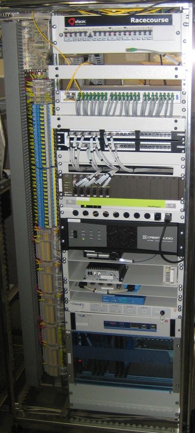
Organization                                                                                                              Or
                                                                                                                            ga
                                                                                                                            ni
                                                                                                                            za
                                                                                                                            tio
                                                                                                                             n

     RPA is a state agency established in December 2001 under the Transport (Railway Infrastructure) Act,
     2001. RPA is responsible for ensuring the provision of light rail and metro infrastructure and top quality
     passenger services.

     Luas is operated by Veolia Transport Ireland, and maintained by Alstom Transport Ireland on behalf of
     RPA.

      Contractor for the Electrical and Mechanical systems (Power Supply, SCADA & Telecoms) on the Luas
      extensions projects

       Sub- contractor for the AVLS and Signalling systems on the Luas extensions projects

      Contractor for the supply of Citadis vehicles

Tramway Dublin                                                                                           Clement Bouvard 16/11/2009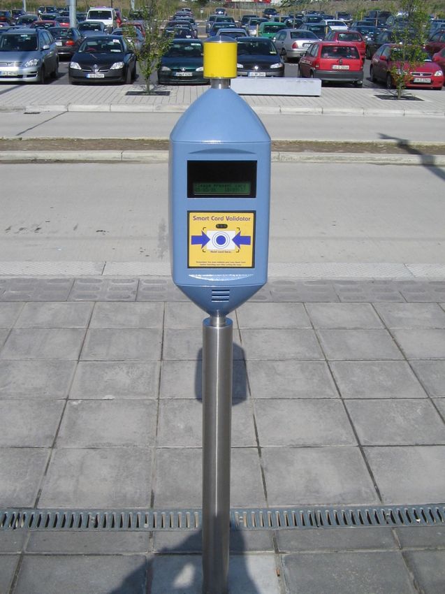
Luas track records                                             Track records

                                         2004 – 6m passengers (part year)
                                         2005 – 22m passengers
                                         2006 – 26m passengers
                                         2007 – 29m passengers
                                         2008 – 27.4m passengers
                                         100,000 passengers carried per day
                                         High off-peak passenger numbers

                                         Responding to passengers:

                                         •Tram frequencies increased: services run from every 4-5 minutes during peak times to every
                                         15 minutes late at night
                                         •30m trams being extended to 40m (40% increase in capacity on Red line)
                                         •Demand for more Luas lines

     RPA Annual report for 2008:

     Luas operates without a State subvention

 Tramway Dublin                                                                                                Clement Bouvard 16/11/2009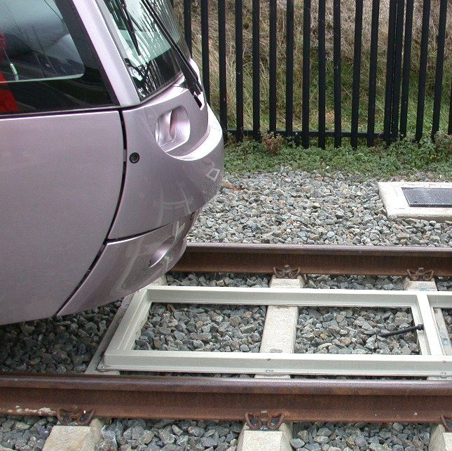
Red line                         Red line

                                                                 Mayor
                                                                 Square                  The Point

                                                      George’s             Spencer
                                                       Dock                 Dock

                                                                     C1 extension (1.5 km)

                 Red Cow depot

                                      Total: 16.5km

Tramway Dublin                                                              Clement Bouvard 16/11/2009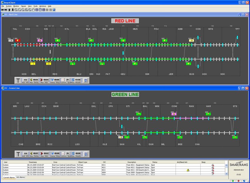
Green line                                   Green line

                                                  Total: 16.5km

                                                                   B1 extension (7.5 km)

                                   Central
                                    Park        The
                                               Gallops            Ballyogan
                                                                    Wood
                                                                                Carrickmines
                                      Glencairn
                                                                                               Laughanstown
                                                    Leopards
                                                      town             Racecourse                             Brides Glen
                 Sandyford depot
                                                                                    Brennanstown
                                                                                                     Cherrywood

Tramway Dublin                                                                             Clement Bouvard 16/11/2009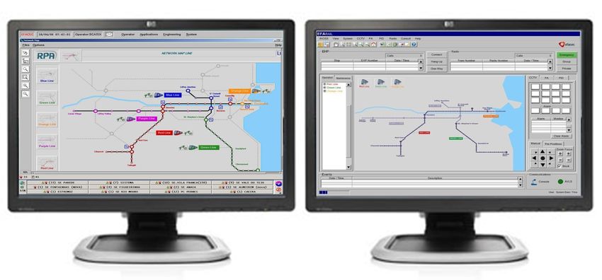
How the Luas works                                    Architecture

                                                               Power control and supervision
                                             SCADA
                                                               Stop equipment control and supervision

                                             AVLS              Tram localization and traffic regulation

                                             Signalling & Depot Control
 Central Control room                        System     Remote point control in the Depot

                                                            Radio & Cable Transmission Network

                        Track side                                                  Stop
                                                                         Fare Collection
                                                                         Public information (Audio, displays)
                                                                         CCTV
                                                                         Emergency Telephone

                                                                           Stop cubicles and
                                                                         electrical substations
                 Road junctions signalling
                 Track and point control                                      AC and DC power
                 Detection loops                                              Operating systems
                 Overhead Contact system

Tramway Dublin                                                                                    Clement Bouvard 16/11/2009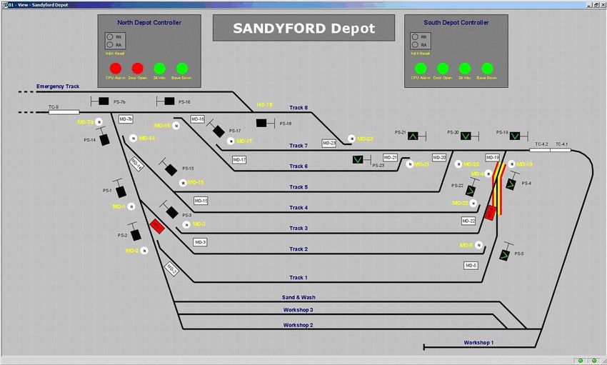
SCADA + Telecommunications (PID/PA/EHP/Radio/CCTV)
Central Control Room          CCR
                       AVLS and Point control

 Tramway Dublin                                                             Clement Bouvard 16/11/2009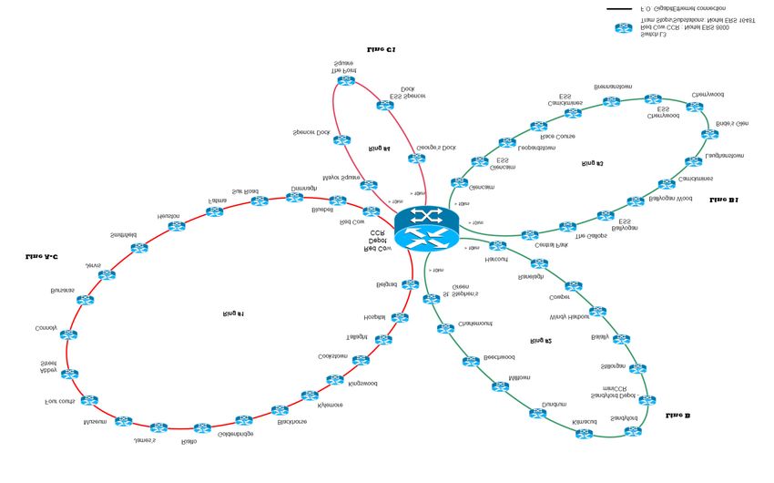
Pictures Pictures
Red Cow Central Control Room Track side equipment
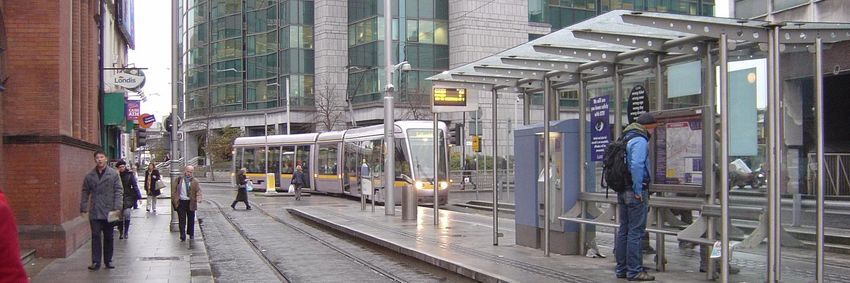
Typical tram stop
Tramway Dublin Clement Bouvard 16/11/2009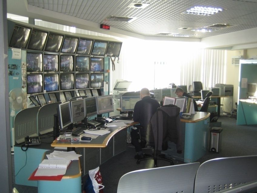
CTN                                                      Stop cubicle

                                                   Main power from
      Stop cubicle

                     2353 mm

                               Systems            Non
                                                  essential             UPS Essential
                               cabinet                                      board
                                                  board

                                                                                        1000 mm

                                                3500 mm

                                        Each tram stop is equipped with a tram stop cubicle
                                    that hosts all the power and electronic equipment.

                                    Material: stainless steel

                                    Manufacturer: Salemo & Merca Lda (Portugal)

Tramway Dublin                                                                                    Clement Bouvard 16/11/2009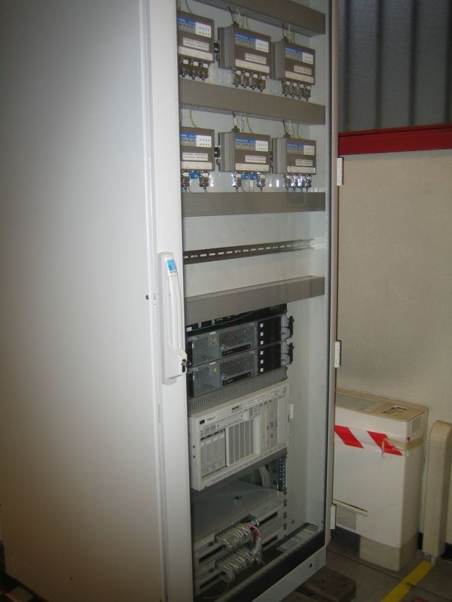
CTN
                                  Stop systems cabinet

      Stop systems cabinet

                                CTN Network

                                  Stop PA

                                   CCTV

                                   AVLS
                             Telephone / EHP

                                 FE SCADA

Tramway Dublin                                           Clement Bouvard 16/11/2009
CTN CTN overview
The Cable Transmission Network (CTN) supports the communications
between tram stops, electrical substations and the Central Control System.
The CTN system is based on a Gigabit Ethernet (GbE) network – 1000Mbps,
using Single Mode fibre optics as the physical transmission media
The network architecture is based in four communication rings
that converges in one central node at the CCR.
Two fibre optic cables run on either side of the tracks (i.e. one
cable on the LV duct side, the other cable on the HV duct side)
Tramway Dublin Clement Bouvard 16/11/2009CTN
Network Control Centre
C For configuration, network management
T and fault diagnosis.
N
e
q
ui
p
m
e
nt Network based on Open Shortest Path First (OSPF)
Routing Protocol: all routers in the routing domain exchange
information between them so that each one knows the
complete topology of the network. Each router defines the
shortest path to all destinations
FO infrastructure
Nortel Ethernet Routing Switch 8600 -
10 slot chassis
Connection to pervious node Connection to next node
(every 2nd stop) (every 2nd stop)
The chassis is equipped with the following modules:
• 3 interface modules of 32 10/100Base-Tx ports + 2 GBIC ports – Optical Distribution frame (ODF)
8632TXE;
• 2 interface module of 8 GBIC ports for GBIC modules with SC
connectors – 8608GBE;
• 2 power supplies 100-240VAC – 8005AC;
Nortel Ethernet
• 2 processor/CPU modules (CPU) – 8691SF / 256MB Routing Switch 1648T
Layer 3 switch with
redundant power supply
RJ45 Patch panel
Stop / ESS
Each stop and substation equipment
Tramway Dublin Clement Bouvard 16/11/2009SCADA / Telecom SCADA / Telecom overview
The SCADA / Telecom system allows the CCR Operators to remotely monitor and control all fixed equipment distributed throughout the Luas system
(CCTV, Passenger Information Display, Public Address, Fare Collection System, Radio, lifts, public lighting) and AC Power Supply, DC traction and
miscellaneous equipment in Electrical Substations.
The EFARail platform integrates two main management applications:
- SCATE X – for the Power Supply SCADA and Fixed Equipment SCADA systems management
- INOSS – for the telecommunications (TLC) systems management
Operator workstation
SCATEX: FE.SCADA - PS.SCADA INOSS: CCTV - PA - PID - EHP - Radio
Tramway Dublin Clement Bouvard 16/11/2009SCADA / Telecom SCADA / Telecom architecture
Architecture
Inoss Scatex
Tramway Dublin Clement Bouvard 16/11/2009SCADA SCADA Scatex CCR
Scada (CCR)
The SCATE X system consists of:
1. Two SCADA Servers, in a hot-standby configuration, as the main processing units
2. Two Communications Front-Ends Servers, responsible for the management of all real time communications links supporting different protocols
and communicating with all sites
3. Two Historical Information Servers (HIS), in a hot-standby configuration, for archiving and historical data storage and statistical analysis of
FE.SCADA, PS.SCADA and TLC systems data
4. One Watchdog computer for the overall system supervision, controlling the change over of the all duplicated system components.
5. Workstations and Degraded Mode Terminals, acting as user interface position with one monitor, handling all operator interactions with the
system through a full graphic user interface
Equipment Qty Supplier Model OS
1
SCADA server 2 HP Proliant ML370 G5 Linux
1
Historical servers 2 HP Proliant ML370 G5
Communication front-end 2 Industrial PC EIPC-100 Win XP
2
2
Watchdog 1 Industrial PC EIPC-100 Win XP
Tramway Dublin Clement Bouvard 16/11/2009SCADA SCADA Scatex stops/ESS
Scada RTU (stops/substations)
Components description:
(1) PS SCADA substations include a local HMI that allows operators to monitor
and control equipment in the substation. Mimics and Alarms descriptions are
common to CCR workstations. Tram stops do not have local HMI
Central unit HMI LCD (1) (2) Central units are used to monitor and process events. They collect data
from the plant equipment either through the acquisition units or directly by
communicating with the equipment (MV and DC relays) and report the
Central units (2) information back to the CCR.
HMI Central unit UC500E central units are a diskless PC based
solution without moving parts with redundant LAN
that supports Windows XP Embedded. Central
Acquisition units (3) units are redundant
(3) Acquisition units have I/O acquiring capability, using I/O boards (digital
inputs through 48Vdc supply to dry relay contacts, digital outputs, analogue
inputs). All changes of states are time-tagged (1ms resolution)
I/O Cable: LiHCH (TP) 21 AWG shielded
Tramway Dublin Clement Bouvard 16/11/2009SCADA SCADA communications
Exchange of information
or
CCR Stop/Substation CCR Stop/Substation
CTN
IEC-870-5-101
IP
IP RS232 IEC-870-5-101 protocol
protocol
RTU (GE Fanuc) RTU (ABB) RTU (Efacec)
Existing stops Existing substations New stops/substations
Tramway Dublin Clement Bouvard 16/11/2009SCADA
PS Red Cow FE Connolly FE Heuston PS Ballaly
FE Harcourt FE Red Cow PS Glencairn FE Goldenbridge
Alarm banner
Tramway Dublin Clement Bouvard 16/11/2009SCADA SCADA PS
MMI
Control
window
PS Red Cow FE Connolly FE Heuston PS Ballaly
FE Harcourt FE Red Cow PS Glencairn FE Goldenbridge
Tramway Dublin Clement Bouvard 16/11/2009SCADA SCADA FE MMI
PS Red Cow FE Connolly FE Heuston PS Ballaly
FE Harcourt FE Red Cow PS Glencairn FE Goldenbridge
Tramway Dublin Clement Bouvard 16/11/2009SCADA SCADA FE MMI
Equipment status
window
PS Red Cow FE Connolly FE Heuston PS Ballaly
FE Harcourt FE Red Cow PS Glencairn FE Goldenbridge
Tramway Dublin Clement Bouvard 16/11/2009SCADA SCADA FE MMI
PS Red Cow FE Connolly FE Heuston PS Ballaly
FE Harcourt FE Red Cow PS Glencairn FE Goldenbridge
Tramway Dublin Clement Bouvard 16/11/2009Telecom SCADA Inoss
Inoss
The INOSS system consists of:
• Data Base Servers : host the core Data Base structures and tables for all TLC subsystems. Alarms and events are also stored in these servers
• Application Servers : host the software applications of all TLC subsystems.
• Regional Application Servers are components of the PID/PA subsystem and are responsible to the network segmentation
• Workstations and Degraded Mode Terminals act as clients of the INOSS applications servers. The graphical user interfaces, providing user friendly
and ergonomic software applications, assures the proper human machine interface for configuring, controlling and managing all telecommunication
subsystems functionalities.
OS
1
Linux
2
Linux 1 2
3
4 Linux
3
4
Tramway Dublin Clement Bouvard 16/11/2009Telecom SCADA Inoss MMI
1
2
5
3 4
6
8
7
1 - Menu bar
2 - Toolbar
3 - EHP bar
4 - Radio RTS bar
5 - Radio call indicator
6 - CCTV/PA/PID Tabs
7 - Explorer Window
8 - Operation Window
10 9 - Events Window
9
10 - Communications status
Tramway Dublin Clement Bouvard 16/11/2009Telecom SCADA Inoss MMI Tramway Dublin Clement Bouvard 16/11/2009
CCTV                                                 CCTV architecture

       Architecture
                                                                                        Central control rooms

               Tram stops (1 camera/platform)           External parties (police, City Council)
               Junctions and crossovers (1 camera)
Tramway Dublin                                                                                             Clement Bouvard 16/11/2009
CCTV CCTV equipment
All cameras are
viewed at 25 IPS, 2
CIF at 2 Mbps.
Equipment
Codec decoder
Bosch VIP XD
decodes video to analogue
signal to display on monitor
Server recorder
HP Proliant DL380
CTN recording management server
IP
Storage unit
Bosh digital video storage
Codec encoder store video in hard disks
video Bosch XJT 10S/20S/40S
encodes camera analogue
signal to IP All cameras are recorded in the CCR recorder
- Continuously for 10 days, CIF at 4 IPS;
Bosch dome camera - On alarm, 1 hour per day during 1 year, CIF at 12 IPS
at stops and junctions
controls
RS-232 Biphase converter
LTC-8786/50
converts data signals between
Codec (RS232) and camera (biphase)
Tramway Dublin Clement Bouvard 16/11/2009CCTV CCTV operation
Operation
Drag/drop to display
Extraction of a video is possible.
Watermarking is used in the authentication
of the video: ensures that an image has not
been edited, damaged, or altered
Manage recordings
Camera number
Workstation (Inoss) view of a tram stop
Tramway Dublin Clement Bouvard 16/11/2009PID PID architecture
Architecture
Arrival time forecast is sent from the AVLS to Inoss
Inoss sends arrival times to the PID at the tram
stops
Tramway Dublin Clement Bouvard 16/11/2009PID PID equipment
Equipment 1 double sided PID per platform (2 units back to back,
1 master / 1 slave) integrated in an advertising drum
Face A Face B
Bride’s Glen 2
Bride’s Glen 8
Welcome to Luas
Light sensor to adjust brightness automatically
Tramway Dublin Clement Bouvard 16/11/2009PID PID operation
Operation
Send a free text message or pre-
recorded message to a PID
Send a free text message or pre-
recorded message to a group of PID
Workstation (Inoss) view of a tram stop
Tramway Dublin Clement Bouvard 16/11/2009PA PA architecture
Architecture
4 speakers / platform mounted on OCS poles
Tramway Dublin Clement Bouvard 16/11/2009PA equipment
PA
Equipment
Audio splitter
Nexia CS
gathers the audio input source and address it to
the correct output (stop audio codec input)
CTN
Audio codec (encoder)
Digigram HitPlayer-L
converts audio signal into a digital
Speakers (4 per platform)
DNH CAP-15W(T)
Audio codec (decoder)
Digigram HitPlayer-L
delivers analogue audio to the stop amplifier
pre-recorded audio messages are recorded in the audio codec
Amplifier
Crest Audio amplifier CKi 150X,
amplifies the low-power electrical analogue
audio signal from the codec, to a suitable level for
driving the loudspeakers line
speakers are cabled on alternate loops, each
connected to a different output on the amplifier
Tramway Dublin Clement Bouvard 16/11/2009PA PA operation
Operation Broadcast a live message or
pre-recorded message
Stops where the message is
being broadcasted + status (if
failed)
Broadcast a live message or pre-
recorded message to a group of stops
Workstation (Inoss) view of a tram stop
The sound level at Stops is lowered automatically at
night (period configurable)
Tramway Dublin Clement Bouvard 16/11/2009EHP EHP architecture
Architecture
1 Emergency Help Point (EHP) / platform
Tramway Dublin Clement Bouvard 16/11/2009EHP equipment
EHP
Equipment
Audio splitter
Nexia CS
gathers the audio input source and address it to
the correct output (stop audio codec input)
CTN Voice modem
Multitech ZDX-V-EU
audio interface
between the operator’s
workstations and the
PABX RS232 Terminal Server
Moxa Nport 6450
gateway between INOSS
TCP/IP interface and the
RS232 Voice Modems
Power over Ethernet (PoE) injector interface
Trendnet
audio interface between the
operator’s workstations and the
PABX
Emergency Help Point
Gai-Tronics
VoIP technology with Induction loop
for hearing aid PABX
Alcatel A4400
Emergency Help Points are integrated to the tram stop
control and establishment of all voice
shelter
communication
Tramway Dublin Clement Bouvard 16/11/2009EHP EHP operation
Jervis EHP IB 4501 11/12/2009 – 14/35/05
Operation
Answer EHP call
Discrete ambiance
listening function
Workstation (Inoss) view of a tram stop
On reception of a call: automatic display of CCTV
image from the camera covering the activated EHP
Tramway Dublin Clement Bouvard 16/11/2009AVLS AVLS overview
Overview
The Automatic Vehicle Location System (AVLS) allows the operator to monitor the location and condition of any tram on
the Luas system, and by doing so to manage the service quality provided by the Luas.
The AVLS system comprises:
• Central control system equipment : servers, workstations
• Peripheral equipment along the line: Selective Vehicle Detection loops, AVLS cabinets
• AVLS on-board equipment: transponder, driver console, onboard computer
• Interfaces with other systems (Radio / PID / Point control / Road Traffic)
Point Controller
Road Traffic
controller AVLS workstation
see Point Control see Road Signalling
interface interface
Tram stop technical cubicle
AVLS AVLS AVLS
INOSS
cabinet Fault Standby
(PID)
see Radio tolerant
interface Serial hub
CTN
Sends the tram arrival
forecast for PIDs
Transponder
AVLS
induction loop
Tramway Dublin Clement Bouvard 16/11/2009AVLS AVLS CCR equipment
1 Fault tolerant Front ends
CCR equipment
Bull Novascale R630 Server
Chipset Intel® 5000V+ NEC Gemini Engine
Processor Front Side Bus speed 1333MHz
Intel® 5000V+ NEC Gemini EngineProcessor Front Side
Bus speed 1333MHzCPU: Quad Core
AVLS workstation
2.66GHz/1333Mhz Intel Xeon ™ processors
3+3 hot-swap SAS disk drives mirrored 146GB (6 total)
1 OS Preload Windows Server 2003 Enterprise Edition
1 2
2
2 Standby server
CTN
Out: In: Bull Novascale T860 E1 Server
• Receives localisation information from
• Calculates tram delay and sends Intel Xeon™ processor E5420 2.5 GHz/2X6MB/
trams
the regularisation commands to 1333 MHz
the trams • Localises the trams along the line and
shows the position on HMI 1+1 hot-swap SAS disk drives mirrored 146GB
• Prepare the service files for AVLS
On Board Equipment • Receives initialisation information from OS Preload Windows Server 2003 Standard Edition
the trams and assigns the service
• Calculates forecast for PIDs
• Receives alarms from trams and shows
these on HMI
Tramway Dublin Clement Bouvard 16/11/2009AVLS AVLS MMI
Stop Arrival Forecast window that shows coming
trams estimated arrival time. This information is
passed to the PID system
Each tram is represented by a
square indicating the tram
number, service number and
advance/delay time and
coloured according to its
schedule adherence status
Road junction. Possibility to
request tram phase remotely
(degraded mode)
Alarm banner
Tramway Dublin Clement Bouvard 16/11/2009AVLS
AVLS
Onboard
equipment
D B B
Onboard equipment
To onboard radio
Manufacturer: Peek Traffic C C
(see radio
interface)
Trigger of the tram information
panels + voice announcements A A
(next stop …)
A
D
C
B
A
A = Transponder: antenna/amplifier mounted on the cab underframe
B = Vecom Box: the physical interface between the Vehicle Processor Box and the transponder.
C = Driver console: displays current service, current trip, final destination, adherence to the schedule, alarms raised by the system
D = Vehicle Processor Box: the central unit of the AVLS on board system. Contains the configuration files (topology of the network) and operational
service files (timetable, service numbers)
Tramway Dublin Clement Bouvard 16/11/2009AVLS AVLS line equipment
Power supply
Line AVLS - Tram number
- Route code Vecom (control)
- Schedule number
- Road junction phase request
(see Road Signalling interface) Loop distribution panels
- Tram direction request (see (up to 16 loops/cabinet)
Point Control interface)
I/O distribution panel
Loop buffer (transmit-
receive amplifier)
AVLS cabinet
Manufacturer: Peek Traffic
- Loop number
IP RS422 RS232
CTN
Tram stop cubicle
Tramway Dublin Clement Bouvard 16/11/2009AVLS
Radio
AVLS interface
Radio interface
Data control channel (short data)
•· Log in / Log off
•· Localisation of vehicle every 10 sec
•· Onboard alarms (rolling stock + AVLS equipment)
•· Pre-coded messages
• Service files CTN
• Regularisation of vehicle (service
adherence ) AVLS Radio
• Synchronisation server switch
• Text messages
In the event of loss of communication between
the onboard AVLS and the AVLS server (e.g. radio
failure), service adherence is calculated
autonomously by the onboard AVLS.
Loop localization Odometer localization Loop localization
Tramway Dublin Clement Bouvard 16/11/2009AVLS AVLS Road signalling / Point control interfaces
Road traffic
Road Signalling / Point control interfaces controller
Point controller
cabinet
AVLS cabinet
Volt free contact
Road Traffic
signal
Phase request (+
Request To Start)
Point movement
(Left / Right) Point position Power supply to
indicator the left and right
electro-valves
AVLS loops
Prepare Demand Stopline Clear
( 300m ) ( 150 m)
Level of priority (High, Medium, Low) is determined on the Prepare Point motor
loop depending on time adherence to the schedule. A different input is sent
to the Road Traffic Controller
Tramway Dublin Clement Bouvard 16/11/2009Point control Point
control
overview
Overview
The Dublin LRT operates on a Line of Sight principle. In case of facing points, which can
be run in normal or reverse position, the driver can control the points according to the
expected route. After the point has been called in the correct position, the signalling logic
provides a safe locking which will maintain the point in position while the tram goes
through.
Points are operated remotely by a Control Room only in the Depots. see AVLS for details of
servers
CTN
5
3m
2 3 4
1 1
1 AVLS loop calls the point
4 Mass detector unlocks the point when cleared
in sequence with the track circuit
Point controller
2 Track Circuit locks the point
5 Point indicator shows the position of the point
3 Point motor (left/right)
Tramway Dublin Clement Bouvard 16/11/2009Point control Point
control
equipme
nt
Equipment (trackside) see AVLS for details of servers
Manufacturer:
The HFP Track Circuits are designed to detect, in a passive way, a rail vehicle and send this information to the Point Controller. This
function is based on the fact that a rail vehicle produces a short-circuit with its axles in the track area.
The minimum length of a HFP track circuit is determined by the
interaxle of the tram bogies. A minimum of two consecutive axles must be
inside the track circuit area to guarantee a safe occupation
Where there is not enough space to install a HFP Track Circuit, the HSK blocking circuit can be used. The length of a HSK Blocking Circuit is 3 to
12 meters and does not depend by the inter-axle dimension of a vehicle:
The HSK blocking circuit recognises the entry of rail vehicles passively by the
wheelshunt produced and it recognises exiting vehicles by the reduction in
vehicle mass detected.
When a vehicle crosses the HSK blocking circuit, its axles produce a short
circuit in the area of the transmitter/receiver module. As soon as the
amplitude drops below a threshold value, the HSK-blocking circuit recognises
the rail vehicle.
After detection of wheel shunt the HSK blocking circuit only monitors the
resonance frequency. When the vehicle leaves the HSK blocking circuit again,
the resonance frequency drops again. As soon as it falls below a threshold
value, the HSK blocking circuit recognises a free track segment again.
Tramway Dublin Clement Bouvard 16/11/2009Point control Point
control
equipment
Equipment (trackside) see AVLS for details of servers
HFK Mass Detector coil are installed behind the point setting mechanism. The
system operates via an electric oscillating circuit, which indicates a change in
frequency when a rail vehicle crosses the HFK mass detector coil with its
metal mass.
For safe protection against humidity and mechanical strain mass detection
coils and electronic components are cast in a plastic frame.
The Point Setting Mechanism for the installation on the line are the models
HWE 61 AVV ZVV. The drive unit operates electro-hydraulically.
The drive and tongue detector lock machine ensures that the open and closed
point tongue is held flush in its end position.
The point setting gear is equipped with a tongue detector. Four non-wearing
inductive approach switches register the defined end positions of the open
and closed point tongue.
The gauge thickness for the Open/Close indication is made by adjusting the
proximity switches. Normally they are set to give a Point Close indication
when the distance between the tongue and the stock rail is 3mm and a Point
open indication when the same distance is 4mm.
Tramway Dublin Clement Bouvard 16/11/2009Point control
Point controller
Point controller main components: 1 5 3 2 4
6
1 2 Central processor units: two-channel microcontroller system with EPROM
for program memory
2 HFP (track circuit) module consists of a single channel transmitter and a two-
channel receiver. The control indicators are on the front plate. The status of
each channel is shown (error, free, occupied). The current measured value
of a channel is shown on an LED strip. Located on the HFP module there is
a step switch for adjusting the operating frequency. Selecting different
operating frequencies will prevent interference between the track circuits.
3 HFK (mass detector) module consists of a single channel transmitter and a
two-channel receiver. The control indicators are on the front plate. The status
of each channel is shown (error, free, occupied). The current measured
value (of a channel) is shown on an LED strip. Slow frequency changes
(temperature drift, component drift) are recognised by the system and
automatically compensated
4 I/O modules provide the connections for the devices and systems outside
the sub-rack (e.g. end position of the point setting mechanism, signals). I/O
are opto-insulated.
5 BIS operating and information module: it displays the function and signal
status of the point controller (display of points position, malfunctions, setting
commands, last setting command, stored setting command). It is possible to
send point movement commands in local mode via the BIS
6 The voltage supply module is connected on the input side with a nominal
voltage of DC 24V. At the output is provides the voltages required for operation
of the electronic plug-in boards.
The individual modules are connected to the operating voltage through a
mains unit. The mains unit has a central cut-out which isolates the operating
voltage from the individual modules in the event of a fault.
Tramway Dublin Clement Bouvard 16/11/2009Point control Point control CCR
Operation
A workstation dedicated to the Line and Depot Signalling is provided to each operator in the Central Control Room. Its function is mostly to:
• Report alarms and equipment diagnostics
• Display the track equipment status and route settings at each shunting zone
Track circuit occupied
Tramway Dublin Clement Bouvard 16/11/2009Point control Depot
control CCR
In the depots, the routes are set remotely by the CCR operator via a dedicated page on the workstation:
Right click: set
point right/left
Tramway Dublin Clement Bouvard 16/11/2009Point control Sandyford signalling overview
Sandyford stop being a more complex zone with many conflicting routes possible, an interlocking solution for the signalling has been implemented.
The signalling system controls not only point indicators but also LRT signals to give safe stop/proceed aspects to the drivers, taking into
consideration status of the trackside elements (track circuits etc…) and conflicting routes set.
Route 16 set
= routes 86 and 46 not permitted by the point
controller
Tramway Dublin Clement Bouvard 16/11/2009Point control Sandyford signalling
operation
Example of route setting at Sandyford stop (route 1 6)
Legend
Locks route/ LRT Signal Point indicator
Right point
AVLS loop (Point command)
Track circuit
Manual route box Motorized switch point
Platform 1
1
6 8
Platform 2
Platform 3
4
Clears route/point Prevents
when cleared 46
86
Tramway Dublin Clement Bouvard 16/11/2009Radio architecture
Radio
Architecture
Tramway Dublin Clement Bouvard 16/11/2009Radio Radio equipment Radio functionalities
integrated into the INOSS
workstaions
The radio communication transmission system allows:
Radio overview
• Audio communications between CCR, tram drivers and service personnel
• Data communication with tram vehicles (AVLS and for onboard alarms)
The radio in Dublin relies on the Dimetra IP Compact system from
Audio splitter (see
Motorola based on the TETRA standard. It uses trunking facility to allow
PA)
a large number of potential users to have sufficient access to a limited
number of resources (shares a set of frequencies instead of providing
them individually).
To digital recorder
GPIOM Module - audio
interfaces for headset. Motorola voice node
Motorola Dimetra IP Compact
Characteristics R6.1 switch is the centralized
Dimensions mm (H, W, D) 1330 ; 600 ; 980 control coordinates and
oversees the operation of the
Digital frequency bands supported 380-430 / 806-870 MHz
individual sites 6 voice channels / Base station
Maximum number of BTS sites 25 2 control channels / Base station
Maximum number of individual radio user IDs 10,000
CTN
Dublin radio provides half duplex E1
IP
communication but has the capability to
be full duplex
IPMUX24 Gateway
Motorola Tetra Station MTS2 at each site
Motorola supervises the equipment and mobile stations
handportable MTP850 at its location
Tramway Dublin Clement Bouvard 16/11/2009Radio Onboard radio equipment
System box 1 System box 2
B B
A A
C
F F
E E
D D
A LHA400 Data & Voice Radio Antennas
System boxes
B Motorola MTM 800 voice and data mobile radios (contains radio and AVLS equipment)
Thales onboard control unit (OBCU):
electronic PC-compatible device that
C interfaces all the on board radio equipments
and AVLS/PA on board Functions
equipments
Foot-pedal: activates radio emergency call +
D
ambient listening in cab + tram flashing lights
Radio Handset: receiver with microphone
capsule, speaker, PTT button, keypad and backlit
E LCD display. Calls privileges are defined by a
phonebook loaded on the OBCU
Cab Loudspeaker with amplifier: CCR operator’s voice
F in group calls and alerts the tram driver of a CCR incoming
call is received
Tramway Dublin Clement Bouvard 16/11/2009Radio
Radio operation
3 types of calls:
- Group call: call a group of subscribers (e.g. all red line trams).
- Private call: call one subscriber
Operation - Emergency call : group call with the highest priority
5004 5004 10/11/12.56
pre
Workstation (Inoss) view
Tramway Dublin Clement Bouvard 16/11/2009AFC
AFC architecture
Fare collection servers
Automatic Fare Collection architecture
IP conversion from old network
to new network
AFC Networks are segregated
from other networks by implementing
Layer 3 Filters on the Nortel Switch /
Routers
Tramway Dublin Clement Bouvard 16/11/2009AFC AFC stop
Automatic Fare Collection at stops
Ticket Vending Machine Smart Card Validator
Manufacturer:
Tramway Dublin Clement Bouvard 16/11/2009CCR migration CCR Migration PROCESS TO MIGRATE THE NEW SYSTEMS INTO THE CENTRAL CONTROL ROOM Tramway Dublin Clement Bouvard 16/11/2009
CCR migration                                        CCTV migration

   1st step: CCTV (3 weeks)
                                                   • CCTV
                                                   • Radio
                                                   • PIDs
                                                   • PA
                                                   • FE SCADA
                                                   • EHPs
        New CCTV                       PS SCADA   Amos (FE SCADA/Telecom)   AVLS          Signalling

     CCTV migration required change of
  configuration of each camera + wiring to the
  codecs / biphase converters at each stop and
  connection to new GbE network

Tramway Dublin                                                                     Clement Bouvard 16/11/2009
CCR migration AVLS migration
The existing AVLS and LSS/DCS serial connections needed to be modified.
A new server cabinet was installed in the technical room: the existing DB25 cables have been
disconnected from the existing AVLS back-up serial interface and connected to the new serial
2nd step: AVLS interface: the existing AVLS back-up FEC was able to communicate with the existing peripheral
cabinets by means of this new AVLS serial interface.
AVLS Signalling
LSS/DCS
AVLS 1
AVLS 2
Switch
Serial
hub
Serial links
OTN
OTN GbE CTN
Serial hub
Cabinet Cabinet
Tramway Dublin Clement Bouvard 16/11/2009CCR migration AVLS migration
2nd step: AVLS
• Radio
• PIDs
• PA
• FE SCADA
• EHPs
New CCTV PS SCADA Amos (FE SCADA/Telecom) New AVLS New Signalling
Tramway Dublin Clement Bouvard 16/11/2009PS SCADA
migration
CCR migration
3rd step: PS SCADA (1 night)
PS SCADA RTUs
Enable SCATEX
Database Client in
CCR
SCATEX
Server
ATOS PS
SCADA Server
Terminal Server
ATOS PS
SCADA Client
in CCR
CCR Substations
Tramway Dublin Clement Bouvard 16/11/2009CCR migration PS SCADA migration
3rd step: PS SCADA (1 night)
• Radio
• PIDs
• PA
• FE SCADA
• EHPs
New CCTV New
PSPS
SCADA
SCADA Amos (FE SCADA/Telecom) New AVLS New Signalling
Tramway Dublin Clement Bouvard 16/11/2009CCR migration Radio migration
4th step: Radio and PID (1 night) Firmware upgrade
INOSS
Client in Hospital
CCR EBTS
New Radio Switch
Localisation Red Cow
EBTS
INOSS
PID Server
Localisation
Forecasts
AVLS Server
PID Liberty
Forecasts EBTS
AMOS
Server
Existing
Radio Switch
Taney
EBTS
•No PID functions
AMOS Client
•No Radio functions
in CCR
Tramway Dublin Clement Bouvard 16/11/2009CCR migration Radio migration
4th step: Radio and PID (1 night)
• Radio
• PIDs
• PA
• Radio
• FE SCADA
• CCTV
• EHPs
• PIDs
New
NewTelecoms
CCTV New PS SCADA Amos (FE SCADA/Telecom) New AVLS New Signalling
Tramway Dublin Clement Bouvard 16/11/2009CCR migration FE SCADA and PA migration
PA migration required wiring to the codecs
at each stop and connection to new GbE
5th step: FE SCADA and PA (1 day) network
FE SCADA migration required enabling
each RTU in the SCATEX server
• PA
• Radio
• FE SCADA
• CCTV
• EHPs
• PIDs
New Telecoms New
New FE PS SCADA
& PS SCADA Amos (FE SCADA/Telecom) New AVLS New Signalling
Tramway Dublin Clement Bouvard 16/11/2009CCR migration EHP migration
EHP migration required an upgrade of the PABX
by adding Alcatel VoIP processing unit cards
6th step: EHP (1 night)
• PA
• Radio
• CCTV • EHPs
• PIDs
New Telecoms New FE & PS SCADA Amos (FE SCADA/Telecom) New AVLS New Signalling
Tramway Dublin Clement Bouvard 16/11/2009End
Thank you
Tramway Dublin Clement Bouvard 16/11/2009You can also read