Mission Critical Network Solutions - April 2021 Technical White Paper - Samsung
←
→
Page content transcription
If your browser does not render page correctly, please read the page content below

Technical White Paper

Mission Critical
Network Solutions
April 2021

Contents

Introduction                                                                                     01
Mission Critical Network Architecture                                                            03
Main Features for Mission Critical Networks                                                      05
MCPTX
eMBMS
D2D / ProSe

Interoperability                                                                                 11
LMR Networks
Commercial Mobile Networks
MCPTX Networks

Evolution of Mission Critical Networks                                                           14
Summary                                                                                          15

Abbreviations
BM-SC     Broadcast-Multicast Service Centre   MME       Mobility Management Entity
CN        Core Network                         P25       Project 25
CP        Cyclic Prefix                        PCRF      Policy and Charging Rules Function
CSC       Common Services Core                 P-GW      PDN Gateway
CSCF      Call Session Control Function        ProSe     Proximity Service
D2D       Device-to-Device                     PS-LTE    Public Safety - Long Term Evolution
DMR       Digital Mobile Radio                 QoS       Quality of Service
eMBMS     Evolved Multimedia                   RAN       Radio Access Network
          Broadcast Multicast Service          RLC       Radio Link Control
eNB       Evolved NodeB                        RoIP-GW   Radio over IP Gateway
EPC       Evolved Packet Core                  SAE GW    System Architecture Evolution Gateway
GCS AS    Group Communication                  SCTP      Stream Control Transmission Protocol
          System Application Server            S-GW      Serving Gateway
HSS       Home Subscriber Server               SIB       System Information Block
IMS       IP Multimedia Subsystem              SIP       Session Initiation Protocol
IWF       Interworking Function                TETRA     Terrestrial Trunked Radio
LMR       Land Mobile Radio                    UE        User Equipment
MC        Mission Critical                     UHF       Ultra High Frequency
MCPTT     Mission Critical Push-To-Talk        VHF       Very High Frequency
MCPTX     Mission Critical Push-To-X           VoLTE     Voice over LTE
MIMO      Multiple Input Multiple Output
Introduction
What is Mission Critical Networks?
Public safety, for any government, is of the utmost importance. In order to protect its citizens from harm such as fires, earthquakes,
terrorist attacks or criminal activity, a government must have reliable safety systems in place. One key aspect of such safety systems
is communication infrastructure, in the form of a mission critical network.
A mission critical network is a dedicated network used by public institutions such as police and fire departments for both day-to-day
operations and in times of emergency. Due to the urgency and cooperative nature of the work that first responders are tasked with,
effective communication plays an important role in emergency response and can be directly correlated with the success or failure of
a given operation.
In legacy mission critical networks, agents in the field have traditionally used push-to-talk radios to communicate among themselves
and with their respective dispatchers. Unfortunately, when the radio technologies deployed by each agency differ, users are forced to
resort to landline phones or mobile phones for cross-agency communication. As a result, when a large-scale disaster occurs and
multiple agencies need to cooperate, response becomes chaotic and disorganized as user relays messages through a multitude of
alternative and untracked lines of communication. Meanwhile, supervisors and dispatchers lose the ability to track who is aware of
which aspects of an often dynamic and evolving situation.
A truly effective mission critical network should be built upon communication infrastructure that is both reliable enough for daily
business and robust enough to serve as an integrated communications system between multiple responding agencies in an
emergency. That is to say, a mission critical network should be equally capable of supporting a routine traffic stop by a single officer,
as well as joint activities between agencies that need to establish on-site cooperation, command, and situation propagation under
the extreme conditions and circumstances of a crisis response.
To overcome the limitations that legacy networks face, a mission critical networks has been specified, developed, and deployed in
recent years. This paper outlines the concept of mission critical networks and how the system is adapted and used in the context of
mission critical networks.

LTE, enabler of modernized mission critical services.
Data connectivity is one of the biggest advantages of mission critical services based on a LTE networks. Before LTE was introduced,
mission critical networks were primarily voice-oriented with support for only very limited data rates. However, with the ability to
transmit high volumes of data and the introduction of LTE features provided by the 3GPP LTE standard, mission critical network based
on LTE can support a wide variety of applications such as live streaming, broadcasting or multi-casting, and device-to-device
communications.
LTE is the technology which is completely based on 3GPP standards and has one of the broadest commercial deployment footprints
in the world today. From these perspectives –openness and popularity- LTE is suitable to unify the existing mission
critical networks based on disparate technologies, such as Very High Frequency (VHF), Ultra High Frequency (UHF) and Terrestrial
Trunked Radio (TETRA), all of which utilize different frequency bands and standards. For example, as shown in Figure 1, the different
networks implemented by the fire department and the railway institution make quick and automatic communications between
agencies difficult. In turn, less efficient communication systems such a landlines need to be used between the agencies. Mission
critical network based on LTE, however, can guarantee faster responses when these different networks are unified through LTE and
also satisfy the rigorous requirements set out for mission critical networks such as resilience, security and quality of service.
3GPP Rel. 13 provides relevant standards and specifications targeted at the functions and requirements for mission critical networks,
including Device-To-Device (D2D) communications, evolved Multimedia Broadcast/Multicast (eMBMS) service, and Mission-Critical
Push-To-Talk (MCPTT).

                                                                                                                                       1
Figure 1. The need for interoperability

                                          2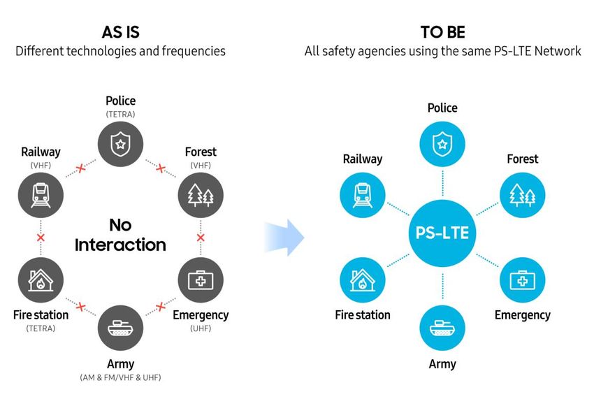
Mission Critical Network Architecture
Because PS-LTE(Public Safety – Long Term Evolution) is a mission critical network based on LTE technology, its network architecture
is essentially the same as commercial LTE networks.
Figure 2 shows the end-to-end network architecture of a typical PS-LTE deployment. It depicts three primary domains: LTE Radio
Access Network (RAN), LTE Core Network (CN), and the IP Multimedia Subsystem (IMS), which includes application servers for Mission
Critical Push-To-Talk, Video and Data (MCPTX).
The LTE RAN and LTE CN domains include the evolved Node B (eNB), Mobility Management Entity (MME), Home Subscriber Server
(HSS), Serving Gateway (S-GW), Packet Data Network Gateway (P-GW), Policy and Charging Rule Function (PCRF) and Multimedia
Broadcast Multicast Service Gateway (MBMS GW). The IMS & MCPTX domain includes the MCPTX Application Server, Common Service
Core (CSC), Dispatcher and Recording server in addition to the IMS HSS and Call Session Control Function (CSCF). The MCPTX
Application Server is one of the most critical elements in the PS-LTE network as it provides primary mission critical network features
such as push-to-talk group and private calling, emergency calling, etc.

                    LTE RAN                            LTE CN                                       IMS & MCPTX

                 Movable eNB            MME             HSS            PCRF              CSCF            CSC         Dispatcher

                                                                                                                     Recording
   PS-LTE UE                            S-GW           P-GW         MBMS-GW            IMS HSS         MCPTX
                                                                                                                      Server

                      eNB

                                                                           LTE network element              MCPTX solution

                                               Figure 2. PS-LTE network architecture

RAN
The RAN is located between the User Equipment (UE) and the core network. It interfaces with the wireless connection according to
the LTE standard and provides wireless communication service to subscribers.

Core Network
The core network is primarily in charge of functions such as the authentication of subscriber information, management of subscriber
location, and connection to the internet network.
The MME is a main control plane element in the PS-LTE network that is responsible for mobility management, signaling, paging,
authentication, authorization, bearer activation/deactivation, Tracking Area (TA) list management, and P-GW and S-GW selection.
The S-GW and P-GW provide connectivity from the UE to the internet network. The S-GW routes and forwards the user data packets
and acts as a mobility anchor point when the user moves between eNBs. The P-GW is responsible for policy enforcement, packet
filtering for each user, charging support, and packet screening.
The PCRF provides real-time policy control decision-making, charging control function, and Quality of Service (QoS) authorization
based on user's profile.
The MBMS GW is a logical entity that is located between the Broadcast Multicast-Service Center (BM-SC) and the eNBs. It is
responsible for the allocation of multicast IP addresses and session management. It receives MBMS content from the BM-SC and
forwards it to the appropriate eNBs over the IP multicast network.

                                                                                                                                    3
IMS & MCPTX
The IMS enables IP-based multimedia services intended for deployment directly within that a mobile network, in contrast to “over-
the-top” services which are hosted outside of the operator’s network. The main services that IMS currently supports are generally
related in some way to voice or video calling. In the case of mission critical networks, group calling is a standout functionality that is
tailored to the specific needs and technical challenges of supporting multi-way communications between (potentially) very large
groups of people.
The CSCF is an IMS entity responsible for handling Session Initiation Protocol (SIP) registration and session establishment and also
acts as SIP routing machinery for services hosted within the IMS, including MCPTX.
The MCPTX Application Server is responsible for handling all media transfer between users, both during private and group call
sessions; such media may include voice, video or data. Critically, the MCPTX Application Server needs to be capable of very rapid
packet processing in order to copy incoming media simultaneously to all others actively listening within a given group. It interworks
with other elements within the MCPTX solution, such as the CSC, to resolve user authorization, group membership, etc.
The CSC is composed of several sub-component management servers:
the ID Management Server (IdMS), which functions as a central point of authentication and token-based service
authorization for user clients;
the Configuration Management Server (CMS), which interworks with the Mission Critical Subscriber Repository to store
and retrieve client configuration and user profile data;
the Group Management Server (GMS), responsible for handling group-related configuration and membership tracking;
the Key Management Server, which stores and distributes relevant encryption keys which are used throughout the solution
for maintaining the security of media and signaling traffic between clients and servers.
In the future, the CSC can be extended to include other management servers such as the Location Management Server (LMS), which
would be responsible for collecting location-related data from clients for use by other servers responsible for Location-based Services.
4Main Features for Mission Critical Networks
Among the broad set of features that LTE delivers, a specific sub-set is particularly useful in the effort to meet stringent service
performance requirements for mission critical networks. Such features (depicted in Figure 3) include Multiple Input Multiple Output
(MIMO), QoS, Voice over LTE (VoLTE), security and eMBMS. On top of these LTE features, mission critical networks introduce its own
focused set of new features such as MCPTX, Proximity Services (ProSe) for D2D communications, Floor Control management, and
Isolated E-UTRAN Operation for Public Safety (IOPS).
PS-LTE
LTE
Multi Carrier Always On Connection MCPTX
D2D (ProSe)
Wide Band MIMO eMBMS
Group Call (GCSE)
Carrier Aggregation QoS Security
Floor Control
CoMP VoLTE Eco-System
Floor Priority
Fast Call Setup IOPS
- MCPTX: Mission Critical Push-To-X - eMBMS: evolved Multimedia Broadcast Multicast Service
- GCSE: Group Communication System Enabler - VoLTE: Voice over LTE
- D2D: Device To Device direct communication - CoMP: Coordinated Multi-Point transmission and reception
- ProSe: Proximity Service - IOPS: Isolated E-UTRAN Operation for Public Safety
Figure 3. Features of LTE and PS-LTE
As shown in Figure 4 below, when features such as MCPTX, eMBMS, ProSe are implemented in a mission critical network, first
responders gain considerable flexibility, ease-of-access and robustness in their ability to handle the work they do, even (and
especially) during unpredictable and chaotic emergency situations. This ability to leverage voice/video group and private
communication, real time image and file transfers, as well as dynamic group management (that allows for ad-hoc groups, location-
based groups, merging groups and more), goes well beyond the capabilities of existing Land Mobile Radio (LMR) and Digital Mobile
Radio (DMR) communication technologies common in the market today.
MCPTX eMBMS ProSe
- Inform the Accident Situation - Real-time Monitor Fire Situation - When Base Station is Broken,
- Request Additional Rescue - Notify of Fire Point & Exit Route Notify Isolated Locations
(Video, Voice, Data) (Video) (D2D Video/Voice/Data)
Ch1 Ch3
Pu
sh Broadcasting Broadcasting
Ch2
Broadcasting
Ch2
Video/Voice/Data
Ch1
D2D
Pu
sh
Figure 4. Main features for mission critical networks
5MCPTX
The MCPTX service delivers group and private communications and features low call setup time, support for very large call groups,
strong media and signaling security. Moreover, it interworks with the broader a mission critical network to support prioritized access
to network resources based on need. These features are pivotal in a mission critical network because the outcome of any given public
safety effort (from community policing to firefighting to disaster response) is directly influenced by the speed, quality and amount of
information that can be communicated as a situation evolves. MCPTX, for this reason, is a key differentiator that sets mission critical
services apart from legacy public safety technologies such as VHF, UHF, TETRA, Project 25 (P25), etc.
As shown in Figure 5, MCPTX group and private communication service is provided on top of the EPC and IMS network and leverages
standard interfaces defined by 3GPP.
A group call is established among users (who are members of a pre-defined or ad-hoc group) when the MCPTX Application Server
sends a group call INVITE to members of the group. A group call can be declared by at different priority levels (e.g., normal or
emergency) by the initiating user, which will indicate to the broader network how to prioritize resource assignment and access
guarantees for the associated bearer setup and traffic handling.
An MCPTX private call is a simple 1:1 call between two users, that can be configured with floor control (push-to-talk) or without (full
duplex; similar to a VoLTE call).
MCPTX Core MCPTX Core
(MCPTX Server, CSC, HSS) (MCPTX Server, CSC, HSS)
EPC and IMS Core EPC and IMS Core
eNB eNB eNB eNB eNB eNB
MCPTX Group MCPTX Group MCPTX Group MCPTX Private
Call originator UE Call participant UEs Call originator UE Call recipient UE
Figure 5. MCPTX call types - group and private
6MCPTX Group Call Setup Flow
A group call setup involves SIP signaling via the EPC network, SIP Core, and MCPTX Application Server. It also involves Floor Control
signaling and Media handling as shown in Figure 6.
PCRF CSC
① Group Call Request ⑤ PCC ④ Service ② Group profile
rule apply Info. retrieval ① Floor Request ②voice or video
EPC IMS MCPTX EPC MCPTX EPC MCPTX
eNB eNB
eNB ①voice or video
⑥ Group Call Response ③ Group Call Request/Response ② Floor Granted ② Floor Taken/Ack
MCPTX Group Call MCPTX Group Call MCPTX Group Call
originating UE participant UE participant UE
eNB eNB eNB eNB eNB eNB eNB eNB eNB
MCPTX Group Call MCPTX Group Call MCPTX Group Call MCPTX Group Call MCPTX Group Call MCPTX Group Call MCPTX Group Call MCPTX Group Call MCPTX Group Call
participant UE participant UE participant UE participant UE participant UE participant UE participant UE participant UE participant UE
(a) Signaling Flow (b) Floor Control Flow (c) Media Flow
Figure 6. MCPTX group call setup flow
Figure 6 - (a) Signaling Flow shows the steps involved in creating a dedicated bearer through the EPC, IMS and MCPTX core as part of
a MCPTX group call setup procedure. When the group call originating MCPTX UE sends a SIP INVITE to the MCPTX Application Server,
the INVITE is further routed to all other participants of the MCPTX group. Next, the IMS core provides MCPTX session information
through the Rx interface to the PCRF, which then requests the establishment of a new dedicated bearer with relevant resources to
meet the required service level for each member of the group call.
Figure 6 – (b) Floor Control Flow depicts how authority is granted to an MCPTX user which allows the user to transmit (talk) during a
MCPTX group call. Floor control is an arbitration service that determines which user has the authority (floor) to transmit at any given
point of a call. When an MCPTX user pushes the button to transmit, the MCPTX UE sends a floor request message to the MCPTX
Application Server. Upon receiving the request, the MCPTX Application Server determines whether or not to grant the request based
on user role and group configuration. If the MCPTX Application Server accepts the request, the floor is granted to the requesting user
and a floor-taken notification is sent to all other participants. Alternatively, the MCPTX Application Server may reject the request for
a variety of reasons. If a user with greater authority already has the floor, then the requesting user will be placed in queue based on
their priority rights (e.g. supervisors before others) with the requesting user duly notified. If a user does not have the right to speak,
then the floor request will be rejected and discarded.
Figure 6 – (c) Media Flow shows the path of RTP media traffic between MCPTX users when an MCPTX user transmits media traffic.
During a group call, only the user granted floor control can transmit media traffic. When other participants in the group call want to
send media traffic, they must first send a floor request message to the MCPTX Application Server.
7eMBMS
eMBMS is a point-to-multipoint service, in which a user delivers common data to a group of interested users through a single, shared,
radio interface. In this case, since radio resources are shared by multiple UEs, eMBMS can significantly improve the spectral efficiency.
This feature is particularly suitable for PS-LTE, where common media (i.e. a single user transmitting at a time) needs to be transferred
to hundreds or thousands of users in a resource-efficient way. In addition, eMBMS enables the coordination of multicast or broadcast
transmission across multiple cells that are tightly synchronized. This technique, called Multicast-Broadcast over a Single Frequency
Network (MBSFN), allows the transmission of identical waveforms at the same time, by constructively superimposing radio signals
from different cells and thus boosting the signal received by the UE. This effect is highly beneficial to UEs located at the cell edge.
Figure 7 shows the basic concept of an MBSFN transmission.
Signal gain within SFN area
Same resource allocation for same eMBMS contents
Large delay Sync.
spread Accuracy
à Extended CP Tight synchronization
required
Figure 7. MBSFN transmission for inter-cell coordinated transmission
Several new network entities are responsible for enabling MBSFN transmission:
Broadcast Multicast-Service Centre (BMSC): The BM-SC is a functional entity responsible for the management of MBMS
sessions (Start, Stop, Update, Delete). These operations are performed based on the request from the MCPTX Application Server.
The BM-SC manages MBMS sessions by allocating a Temporary Mobile Group Identity (TMGI) which is unique to each session.
Based on the TMGI, the BM-SC requests for specific MBMS bearers for MBMS Session Start, Stop, Update and Delete. At the
same time, the BM-SC handles user plane traffic which is delivered over each session. In order to process user plane traffic, the
BM-SC uses the Synchronization (SYNC) protocol to ensure precise synchronization of user data packets as they are
simultaneously transmitted from multiple eNBs. In Samsung’s MCPTX solution, the BM-SC is implemented as a sub-function
of the MCPTX Application Server itself in order to support broadcasting for MCPTX downlink media traffic.
MBMS Gateway (MBMS-GW): The MBMS-GW is a functional entity responsible for the allocation of multicast IP addresses and
session management. It receives MBMS content from the BM-SC and forwards it to the appropriate eNBs over the IP multicast
network. The MBMS-GW can optionally be integrated with the P-GW.
Multicell and Multicast Coordination Entity (MCE): The MCE is a new network entity that allocates and schedules the same
radio resource to multiple cells for MBSFN transmission. In addition, the MCE performs MBMS session admission control and
manages eMBMS services. In an eMBMS system, each eNB is served by a single MCE at a given time, though each eNB can
receive multicast traffic from multiple MBMS-GWs. The MCE can be deployed in two different ways: centralized or distributed.
In a distributed deployment, the MCE is integrated directly into each eNB whereas in a centralized deployment, the MCE
functions are implemented in a separate server. Table 1 shows the difference of centralized MCE and distributed MCE.
8Centralized MCE Distributed/Integrated MCE in eNB
Stream Control Transmission Protocol (SCTP)
Increased SCTP load at MME
offloading at MME
Easy to support eNB restoration Not easy to support eNB restoration
Requires an additional server for MCE No extra server required
Needs SFN synchronization between eNB and No need SFN synchronization between eNB and
MCE MCE
Advantageous for large service are (e.g.,
Advantageous for small service area (e.g., stadium)
City/Nation)
Table 1. The difference between centralized MCE and integrated MCE
The aforementioned network entities are interconnected through the following new interfaces:
M1 interface: A user plane interface connecting the eMBMS-GW and eNB. eMBMS-GW delivers MBMS data using IP multicast
over the M1 interface. SYNC PDU for synchronization is delivered over the M1 interface.
M2 interface: A control plane interface located between the MCE and eNB. Accordingly, only a centralized MCE has the M2
interface (i.e., there is no M2 interface for the integrated MCE in eNB). The connection specification must satisfy the SCTP
interface.
M3 interface: The MCE and MME are connected by the M3 interface. The connection specification must satisfy the SCTP
interface.
Figure 8 shows eMBMS architecture for MCPTX with the three new interfaces, M1, M2 and M3.
Existing LTE Interface
MCE
New MCPTX Interface for eMBMS
MBSFN M2 M3
Area
Internet
MME
Sm
SAE GW MCPTX Server
SGmb MB2-C
MBMS
SGi-mb BM-SC MB2-U GCS AS
GW
M1 (Multicast)
UEs eNB
- MCE: Multi-Cell/Multicast Coordination Entity - M1: User plane interface between MBMS GW and E-UTRAN
- BM-SC: Broadcast & Multicast Service Center - M2: E-UTRAN internal control plane interface
- MBSFN: Multicast Broadcast Single Frequency Network - M3: Control plane interface between E-UTRAN and EPC
- Sm: Control plane interface between MME and MBMS GW
- SGi-mb: User plane interface between BM-SC and MBMS GW
- SGmb: Control plane interface between BM-SC and MBMS GW
- SGi: The reference point between the EPC based PLMN and the packet data network
Figure 8. eMBMS architecture for MCPTX
In a PS-LTE network, eMBMS can be used to improve the capability and efficiency of group calling. Since these types of calls are
fundamentally one-way, real-time and fixed (i.e. all users receive the exact same media at the exact same time from a single user
transmitting), the use of a broadcast channel for transmitting the same downlink data to multiple clients is of extreme benefit in
terms of network resource usage, both on the radio side (spectrum usage) and within the backhaul and the core network. Considering
9that a MCPTX service can reach thousands of simultaneous users, many of whom are likely to be in close proximity, MBMS serves as
a reasonable solution for transmitting the same data simultaneously to mass audiences. Moreover, as MCPTT usage is further
augmented by MCVideo, eMBMS will play a critical role in ensuring service capabilities despite the limited spectrum resources that
are typically dedicated to public safety usage.
It should be noted that eMBMS is useful only for downlink traffic to multiple simultaneous recipients. Uplink traffic (user transmission),
as well as downlink traffic that is unique to each user (certain floor control messaging, e.g. a user’s place in queue), will continue to
use the standard unicast transmission methods.
D2D / ProSe
Direct communication between devices (D2D) can be implemented using the 3GPP ProSe feature. ProSe allows a UE to discover other
UEs that are within close proximity while off-network (i.e., not served by an eNB or connected to the LTE CN in any way). While ProSe
can potentially be used for normal commercial service, this paper focuses on how it can be used in public safety use cases.
Once a ProSe-enabled UE has discovered another ProSe-enabled UE, the devices can communicate (transmit user plane traffic)
directly to one another without having the data routed to a network infrastructure. In general, there are two direct communication
methods: one-to-one or one-to-many. As an extended use case, a ProSe-enabled UE within network coverage can function as a relay
for nearby devices which are outside of the coverage footprint – a so-called UE-to-Network Relay – in order to provide network access
to the off-network devices.
Figure 9 shows all these three use cases of D2D/ProSe in details.
One-to-many (Group) One-to-one (Private)
UE-to-Network Relay
Communication Communication
Unicast/Multicast MCPTX
Unicast
Multicast Initiating UE Target UE Remote Relay UE
UE
[Out-of-coverage] [Out-of-coverage] [Partial-coverage]
Communication with the group Communication between two UEs Relay UE provides the connectivity to the Network
members belonging to the same group - Initiating UE discovers the target UE’s for Remote UE
- Use pre-configured Multicast IP Layer-2 UE ID - Remote UE discovers the Relay UE’s Layer-2 ID
address & Layer-2 Group ID for the - Link setup signaling between two UEs - Relay UE relay unicast traffic (UL/DL) between the
specific group - IP address configuration (DHCPv4 or Remote UE and the Network using 1:1 communication
IPv6 RS/RA) - Relay UE relay eMBMS traffic using 1:N
communication
Figure 9. D2D / ProSe service
In order to ensure that only authorized devices can use ProSe services, a ProSe-enabled UE must be connected to the network at least
once within a given timeframe to receive the necessary authorization credentials from the LTE CN and any associated services, such
as the MCPTX Application Server. This ensures that service operation and access are properly secured, as well as preventing
unauthorized usage of licensed spectrum resources.
10Interoperability
LMR Networks
Interoperability of mission critical networks with existing legacy systems, such as TETRA/P25 networks, can be implemented where
needed in order to facilitate a smooth transition to newer technologies without disrupting current service capabilities. There are two
options for MCPTX – LMR(Land Mobile Radio) Interworking as depicted in Figure 10. On the device end, an LMR device can interconnect
with the MCPTX service using Radio over IP Gateway (RoIP-GW). This is currently the more commonly considered approach; however,
it requires broad, distributed deployment of RoIP-GW elements at multiple points throughout the LMR radio network in order to
bridge coverage. Alternatively, the LMR core network can be more directly interconnected to the MCPTX service via a standardized
interface on the LMR side (e.g. TETRA Inter-System Interface (ISI) or P25 Inter Subsystem Interface (ISSI)) through an LMR-
Interworking Function (LMR-IWF) at the edge of the IMS/MCPTX core. The LMR-IWF is responsible for “translating” the
implementations of each technology to the other, such that LMR users and groups appear as MCPTX users/groups from the MCPTX
side, and vice versa for the LMR side. This effectively enables mission critical group and private voice communications between
mission critical networks and LMR networks, through a centrally deployed gateway, significantly reducing deployment complexity
and cost as compared to RoIP-GW deployments.
TETRA/P25 Core LMR-IWF MCPTX
LTE Network
RoIP-GW
Figure 10. Interoperability with TETRA/P25 networks
11Commercial Mobile Networks
The nature of a mission critical network is often unpredictable and not confined to a fixed set of locations. Thus, its subscribers need
to be able to communicate at any time and from anywhere. In other words, the mission critical network must be accessible even in
cases where coverage is not necessarily deployed (coverage holes).
Fortunately, PS-LTE is fundamentally based on LTE technologies, which have one of broadest commercial deployment footprints in
the world today. Taking advantage of this fact, PS-LTE users can easily roam on to commercial networks and even access services
such as MCPTX should they find themselves out of range of their home PS-LTE network.
There are various interworking methods between PS-LTE and commercial LTE networks. Figure 11 illustrates one such method in the
case of multiple Public Land Mobile Networks (PLMNs).
Operator A PS-LTE LTE-R/M
PLMN A PLMN B PLMN C
PLMN B PLMN B
PLMN A PLMN C
eNB eNB
eNB Movable eNB
PLMN B PLMN B
UE PS-LTE UE PS-LTE UE PS-LTE UE LTE-R/M UE
Figure 11. Interoperability between PS-LTE and commercial LTE networks
PLMNs are identified by a five or six-digit number that consists of the Mobile Country Code (MCC) and the Mobile Network Code (MNC).
Every mobile service provider, including a PS-LTE operator, has a unique PLMN to distinguish itself.
In a Multiple-PLMN implementation, LTE service is provided to users in a given cell that supports multiple concurrent operators. For
this approach to work, the RAN must be set up to broadcast multiple PLMNs through its system information and select the relevant
core networks based on the PLMN requested by the UE. This would be implemented as part of a public safety deployment in
coordination with commercial networks roaming partners.
The steps involved in PS-LTE and commercial LTE interworking are highlighted as follows:
The PLMN code of a PS-LTE network is provisioned by the RAN of a commercial LTE operator.
The commercial RAN periodically broadcasts an SIB1 message which includes the PS-LTE PLMN code (in addition to the
commercial operator’s own PLMN code).
If a UE requests a PS-LTE PLMN, the commercial LTE RAN routes the signaling message to the MME located in the PS-LTE
network in order to set up a connection towards the PS-LTE network.
The Multiple-PLMN approach can also be used to allow PS-LTE networks to interwork with other comprehensive safety networks,
such as LTE-Rail (LTE-R) or LTE-Marine (LTE-M) networks. The ability to interwork all of these various network deployments in both
the public safety and commercial domains is a fundamental benefit of an LTE-based ecosystem.
12MCPTX Networks
There are several cases to consider in which multiple different MCPTX(Mission Critical Push-To-X) networks may be required to
interwork with one another. In some cases, mission critical networks may be deployed in a regionalized manner (e.g. individual state,
province, city or even agency networks), in which case users on these networks will find a need to communicate with each other during
a major emergency. Another case to consider is cross-border operations between two or more nations. Additionally, we also expect to
see deployments by commercial operators themselves, both targeted at first responders, but also at enterprise users for so-called
business-critical service.
In each of these cases, the MCPTX applications can interwork with each other via standard interfaces defined by the 3GPP. Within a
single operator’s network, the interworking among multiple MCPTX Application Servers is achieved using the MCPTT-3 interface.
However, across multiple operators’ networks, the MCPTT-10 interface is used instead in conjunction with a Mission Critical Gateway
at the edge of each network in order to ensure security of communications entering each network as well as to implement topology
hiding such that neither network is aware of the internal details of the other network. Figure 12 shows interoperability between two
operators’ network over the MCPTT-10 interface.
MCPTT-3 MCPTT-3 MCPTT-3 MCPTT-3
MCPTX-2 MCPTX-2
MC-GW MCPTT-10 MC-GW
MCPTX-1 MCPTX-3 MCPTX-1 MCPTX-3
Topology Hiding Topology Hiding
Signaling proxy Signaling proxy
Public Safety MCPTX Enterprise MCPTX
SGi, Rx LTE Network SGi, Rx
Core
RAN RAN
Figure 12. Interoperability with other MCPTX
This type of standard interworking among different MCPTX networks provides additional flexibility to Mission Critical service
operators and government agencies to manage and control emergency situations.
13Evolution of Mission Critical Networks
Arguably, the most key feature within mission critical networks is MCPTX. It replaces traditional push-to-talk technology and
promises to revolutionize how first responders communicate in the course of their work. Utilizing LTE technology, various applications
such as video and data, on top of traditional voice calling, can be leveraged in mission critical circumstances. In addition, with the
Group Communication System Enabler (GCSE) technology applied, video, data, and voice can be efficiently transmitted using eMBMS-
based multicasting so that networks can better cope with chaotic and unpredictable demands on radio and transport resources during
emergency situations.
The discussion around mission critical networks began in Rel. 12 of the 3GPP specification, with Mission Critical Push-To-Talk (MCPTT)
having been defined in Rel. 13. In 3GPP Rel. 14 and Rel. 15, these two features – PS-LTE and MCPTT -were enhanced. Samsung MCPTX
solutions based on the latest Rel. 15 are expected to be ready in 2020. Major features include, supporting MBMS-based mission critical
communications, interworking with existing LMR networks, interworking with other MCPTX, among others.
In many countries, the need to interwork with existing LMR networks is of fundamental importance due to the widespread nature of
LMR, the deep integration of LMR into current standard operating procedures, as well as the typical length and considerable cost of
existing LMR operation agreements. Basic LMR interworking using RoIP-GW is already possible today, with the more comprehensive
LMR-IWF approach expected to be available within 2020.
While many operators are pursuing 5G deployments now at a rapid pace, it should be noted that mission critical services in 5G NR
(sometimes referred to as PS-5G) are still in the infant stage, with early study items only now being conducted. Some advanced
features, such as ‘grant-free UL’ and ‘eMBB-URLLC multiplexing’ are reflected in the 3GPP standard which tap into some 5G-oriented
concepts, but practical 5G-based mission critical services aren’t expected to be defined until Release 17 or Release 18 at the earliest.
Figure 13 shows the evolution of mission critical features.
Samsung Supported 2019 Samsung Supported 2020 Samsung Supported 2021
3GPP Rel.12
3GPP Rel.15 (2018) 3GPP Rel.16 (2019)
(Specification Released: 2015)
Enhancements to MCx
Proximity-based Services (ProSe) Enhancements to MCx
- Remote MCPTT Call Attempt
- Call type-& service-based priority/
- Ad-Hoc Group MCPTT Calling
QoS adjustment
- Emergency Private MCVideo
- Location-based services
Group Communication Calling
enhancements
System Enabler (GCSE) - Ambient Listening
Enhancements to MCx
3GPP Rel.12 (2016) - eMBMS-based MCx broadcast- Enhancements to MCCI/MCSMI
multicast
- Defined methods for MCVideo/
Data via eMBMS
Mission Critical
- Forward Error Correction for MC Service over 5G Study Item
Push-To-Talk (MCPTT)
MBMS media
- Header compression
- Multi-server bearer coordination
Enhancement to ProSe (eProSe)
MC Communication Interworking
(MCCI)
- Interworking between LTE and
MBMS Enhancement
non-LTE MCPTX systems
- Legacy interworking
(e.g. LTE? P25, LTE? TETRA)
Isolated E-UTRAN Operation for
Public Safety (IOPS)
MC System Migration and
Interconnection (MCSMI)
3GPP Rel.14 (2017) - MC Server Interworking (cross-
service, cross-operator)
- UE mobility between networks
Enhancement to MCPTT (eMCPTT)
Mission Critical Video (MCVideo)
Mission Critical Data (MCData)
Figure 13. Evolution of mission critical network’s features
14Summary
The primary purpose of a mission critical network is to keep citizens safe both on a daily basis from criminal activity, fires, etc., as well
as during the course of disasters such as earthquakes or terrorist attack. In order to satisfy the unique requirements of first responders
during such a broad array of situations, mission critical networks based on capabilities of LTE which is data-oriented technology have
long been discussed. Because of its data-oriented nature it can transfer high volumes of data (e.g. video streaming or files) to its users.
This is important as the way that first responders communicate and handle their work is evolving in much the same direction – data-
oriented with a higher reliance on digital systems to manage operations. Since PS-LTE itself is based on LTE, it can take advantage of
the same LTE technologies and features that have been field-proven in commercial networks over the past decade, while adding a
few new features to improve its overall reliability, efficiency and service capabilities in line with the unique demands of public safety.
Samsung has been a pioneer in the mobile telecommunications market for more than two decades. Armed with considerable
knowledge and technical experience in a variety of key technologies, such as VoLTE and eMBMS, as well as its position as an end-to-
end LTE solution vendor, Samsung has become one of the industry’s strongest solution providers for PS-LTE network deployments.
Moreover, Samsung has also participated in the establishment of global standards for PS-LTE and is the world's first standards-
based nationwide PS-LTE solution provider. With nationwide coverage, the network serves as a unified platform that helps ensure
interoperability among various public safety institutions. This delivers real-time accessibility and enhanced communication
capabilities among public safety agencies and personnel in emergency situations.
With its dedication to providing world-class solutions, Samsung incorporates only the most reliable and efficient technologies and
services into its mission critical network portfolio and works closely with its customers to ensure deployments suit the needs of
operator, end-users and market alike.
15About Samsung Electronics Co., Ltd. ⓒ 2021 Samsung Electronics Co., Ltd.
Samsung inspires the world and shapes the future with All rights reserved. Information in this leaflet is proprietary to
transformative ideas and technologies. The company is redefining Samsung Electronics Co., Ltd. and is subject to change without
the worlds of TVs, smartphones, wearable devices, tablets, digital notice. No information contained here may be copied, translated,
appliances, network systems, and memory, system LSI, foundry and transcribed or duplicated by any form without the prior written
LED solutions. consent of Samsung Electronics.
Address : 129 Samsung-ro, Yeongtong-gu, Suwon-si Gyeonggi-do, Korea
Homepage & Insight Youtube
www.samsungnetworks.com
www.samsung.com/global/business/networks/insights www.youtube.com/samsung5g
16You can also read