DigiTRON Electrical Flying Leads, Jumpers and Harness Assemblies Site Received Test Manual - Document No: SRT-001
←
→
Page content transcription
If your browser does not render page correctly, please read the page content below
Document No:   SRT-001
                             Issue Date:    02/02/2021
                             Revision:      07
                             Page:          1 of 17

Document No: SRT-001

DigiTRON Electrical Flying Leads,
Jumpers and Harness Assemblies
Site Received Test Manual

    Unrestricted
Document No:     SRT-001
                                                                                        Issue Date:      02/02/2021
                                                                                        Revision:        07
                                                                                        Page:            2 of 17

     Thank you for purchasing a Siemens Energy Subsea product.

                                                   IMPORTANT
                                       READ CAREFULLY BEFORE USE
                                       KEEP FOR FUTURE REFERENCE

       This document must be read in conjunction with the Installation, Operation
          and Maintenance document IOM-001, which contains all specifications,
                      product use instructions and product safety information.

                        This can be found on Siemens Energy Subsea website
                          https://www.siemens-energy.com / search Subsea

 07       J. Keith        02/02/2021   D. Church     02/02/2021   IR storage and temperature statement
                                                                  added to section 11.

 6        R. Wyatt        25/09/2020   R. Wyatt      25/09/2020   Statement added to use this document in
                                                                  conjunction with IOM-001.
                                                                  H&S section updated. Contact details
                                                                  added.
 5        L.Belcher       04/10/2018   J.P.Smith     04/10/2018   Ethernet testing added throughout . Earth
                                                                  CP core test note added

 4        L.Belcher       09.06.2015   M.D.Bell      09.06.2015   Warning note with regard to lifting and PPE
                                                                  added at Section 6. Cable Assemblies
                                                                  added to IR in section 11.
 3        P.Westwell      29.4.2014    B.Leach       29.4.2014    New Cover design & complete document
                                                                  reformat.

 2        L.Belcher                    B.Leach       18.3.2014    Re-format, various text amendments,
                                                                  general updates
 1        P.Westwell                   B.Leach       1.8.2013     First issue

               By           Date           By          Issue
                                                        Date
Rev            Compiled                          Checked                          Remarks
© Siemens Subsea Connectors,                                                     Page No.
(a division of Siemens plc), Subsea Excellence                                      2
Centre, Ulverston, Cumbria, LA12 9EE, England

     Unrestricted
Document No:            SRT-001
                                                                                                           Issue Date:             02/02/2021
                                                                                                           Revision:               07
                                                                                                           Page:                   3 of 17

Contents

1.             INTRODUCTION........................................................................................... 4
2.             SCOPE.......................................................................................................... 4
3.             CONTACT DETAILS AND FEEDBACK ...................................................... 4
4.             ABBREVIATIONS ........................................................................................ 5
5.             PURPOSE..................................................................................................... 6
6.             RESPONSIBILITIES ..................................................................................... 6
7.             HEALTH & SAFETY ..................................................................................... 6
8.             VISUAL INSPECTION AND CHECKS ......................................................... 7
9.             ELECTRICAL TESTING ............................................................................... 9
10.            CONTINUITY TEST .................................................................................... 10
11.            IR TEST ...................................................................................................... 12
12.            CUSTOMER COMMENTS / FEEDBACK ................................................... 17

Unrestricted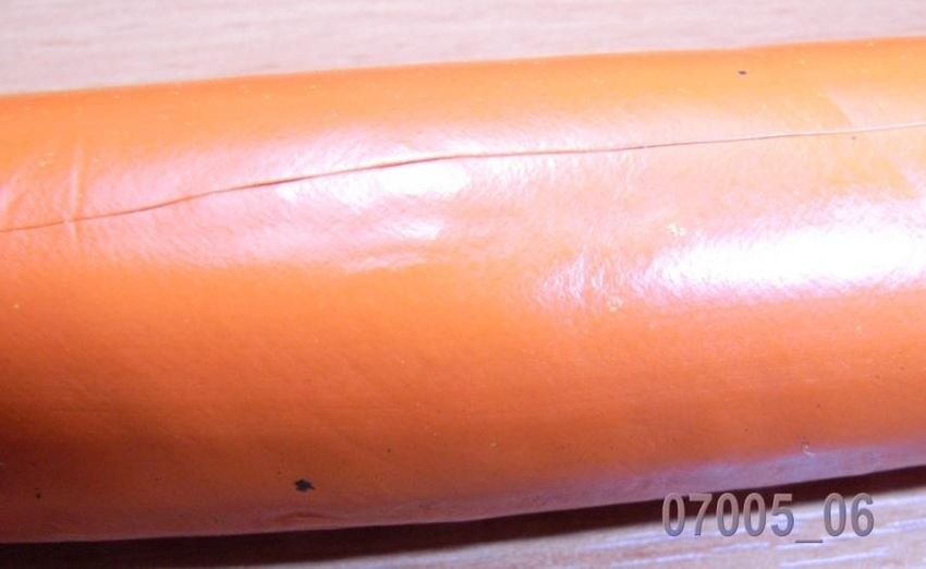
Document No:     SRT-001
                                                                        Issue Date:      02/02/2021
                                                                        Revision:        07
                                                                        Page:            4 of 17

 1. INTRODUCTION
 This document is to provide the customer a simple test and check procedure to perform on
 receipt of supplied Electrical Flying Leads, Jumpers and Harnesses to confirm
 identification, quality and operation.
 .
 This document must be read in conjunction with the Installation, Operation and
 Maintenance document IOM-001, which contains all specifications, product use
 instructions and product safety information.

 This can be found on Siemens Energy Subsea website https://www.siemens-energy.com
 /search Subsea

 2. SCOPE
 This document defines the procedure and equipment required to carry out the Site
 Received Test on Electrical Flying Leads, Jumper and Harness. This is to determine no
 damage has taken place in transit and the EFL / JUMPER / HARNESS is fit to be
 deployed. This test will also confirm basic electrical performance.

 3. CONTACT DETAILS AND FEEDBACK
 For additional information or questions regards the products visit the Siemens Energy
 website www.Siemens Energy.com/subsea /search Subsea or contact the following.

Department                                  E-mail address
                                            subsea.connectors.productsafety.gb@siemens-
Product Safety Officer
                                            energy.com
Technical Support                           connectortechnicalsupport.gb@siemens-energy.com

Service (Site Team)                         susultlcmsupport.gb@siemens-energy.com

Sales                                       connectorsales.gb@siemens-energy.com

 Any information, records, or Health and Safety feedback that needs to be detailed can be
 recorded in section 13 of this document and sent to the relevant email address.

 Unrestricted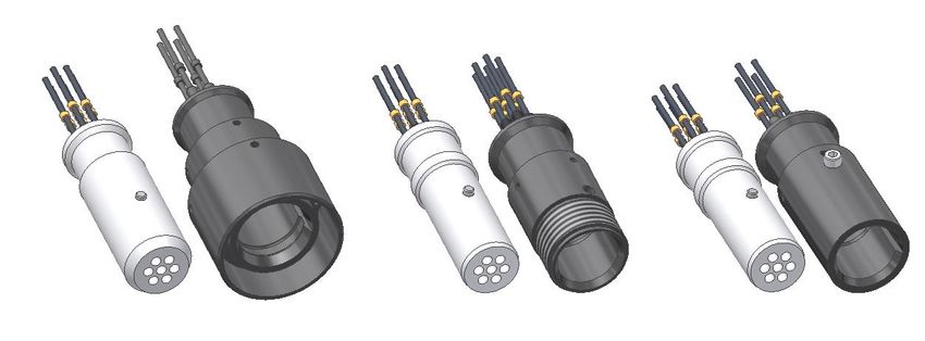
Document No:   SRT-001
                                                                Issue Date:    02/02/2021
                                                                Revision:      07
                                                                Page:          5 of 17

4. ABBREVIATIONS

A              Ampere
AC             Alternating Current
Assy           Assembly
API            American Petroleum Institute
AWG            American Wire Gauge
BOM            Bill of Material
°C             Degree Celsius
CE             Community European
Comms          Communication Signal
CP             Cathodic Protection
DC             Direct Current
DWG            Drawing
EFL            Electrical Flying Leads
EMF            Electrical Magnetic field
FAT            Factory Acceptance Test
IR             Insulation Resistance
ISO            International Organization for Standardization
ITP            Inspection Test Plan
K              Kelvin
LTC            Long Term Cover
M              Metres
Max.           Maximum
MFG            Manufacturer
Min.           Minimum
No.            Number
ROV            Remotely Operated Vehicle
SI             Standard International
SRT            Site Received Test
SST            Stainless Steel
TBD            To Be Defined
TSP            Twisted Screened Pairs
UNS            Unified Numbering System for Metals and Alloys
V              Volt

Unrestricted
Document No: SRT-001
Issue Date: 02/02/2021
Revision: 07
Page: 6 of 17
5. PURPOSE
The purpose of this document is to ensure that the Site Received Test is performed where
specified, on all AquaTRON oil-filled electrical jumpers and cable harness assemblies. IR
and Continuity tests will be performed along with a visual inspection for any damage pre
and post test.
6. RESPONSIBILITIES
It is the operators’ responsibility to comply with this instruction and to ensure all test
equipment is within calibration and report any problems to the Quality Control Inspector.
The operator shall also be responsible for completing the Test Results Sheets.
All tests shall be carried out within a test cell, or specifically designed test area, which shall
be clearly identified. Controlled access to such areas shall be enforced.
Care must be taken during handling, any damage to the hose or connectors can result in
schedule delays.
7. HEALTH & SAFETY
Before any work begins, document IOM-001 must be referred to for safety
information relating to the product and use of.
Only suitably qualified and experienced persons (SQEP) should perform the tasks listed in
this document.
All high voltage equipment should have been checked for safety within the last 12 months
from the date of use.
The operator shall be protected from electrocution by earth-screened enclosures that
contain the H.V. hazard.
After every H.V. test, an earth stick shall be used to ensure that the conductors are
discharged.
For tests involving D.C. sufficient time must be allowed for the circuit to discharge before
touching the conductors. The discharge period shall be at least equal to the period of
charging.
UnrestrictedDocument No: SRT-001
Issue Date: 02/02/2021
Revision: 07
Page: 7 of 17
8. VISUAL INSPECTION AND CHECKS
• Upon receipt of EFL / Jumper / Harness please handle in accordance with
procedures detailed in the IOM manual.
• Each page of this document contains a signature section to be completed by the
user.
• Visual inspection for damage to be completed by Siemens trained technician.
Please use check box as shown Pass ✓ Fail
Check EFL / Jumper / harness and connectors are correct to parts ordered. If EFL
is terminated with incorrect parts please stop test and inform Technical Dept............
Lay out EFL flat on a clean surface and check entire length for any visual damage or leaks.
Some example images can be found below and on next page........................
Ensure hose is straight and check length against GA drawing....................................
Remove protective caps from connectors and check contact face / seal for Debris or
damage.......................................................................................................................
Check pins / sockets for damage.................................................................................
Inspect connector body for any impact damage, scratches..........................................
Re-install protective caps.............................................................................................
Check tagging and etching is to project requirements..................................................
Any failure to this criterion must be recorded on the Information and Notes / Health and
Safety Feedback list at the back of this document and the technical department must be
informed.
Photos must be taken as evidence to help rectify any non-conformance.
Example images: To help
identify hose damage, debris,
defects and fading.
Check Hose surface for damage
such as cuts, rips, tears, leaks
and deformity.
(Picture shows cut in hose)
UnrestrictedDocument No: SRT-001
Issue Date: 02/02/2021
Revision: 07
Page: 8 of 17
Check hose for discolouration and surface deformity.
Faded hoses can be acceptable so
long as they are in good condition
with no leaks or cracks.
(Picture shows deformity)
Hose / Cable minimum bend
radius must NOT be less than
stated, this could result in
damage to the Hose / Cable
Minimum Bend Radius
Aquatron 50 Hose……..125 mm
Aquatron 75 Hose……..180 mm
Tronic 2 Core cable……273 mm
Tronic 4 Core cable……273 mm
Tronic 7 Core cable……300 mm
Tronic 12 Core cable…..400 mm
Make sure all contacts and mating faces
are Clean and free from debris.
(Picture shows debris in contact)
UnrestrictedDocument No: SRT-001
Issue Date: 02/02/2021
Revision: 07
Page: 9 of 17
9. ELECTRICAL TESTING
ALL TESTS TO BE PERFORMED BY SIEMENS/CLIENT TRAINED OPERATIVES
ONLY.
General Equipment;-
Ambient temperature / humidity recorder
Barometer
Record atmospheric pressure, temperature & humidity (in accordance with the IEC
60060 standard) during electrical & function testing
Note: All calibrated equipment must have a current calibration certification at the time
of the test. Details must be recorded on the results Record Sheets included in this
document
The appropriate test connector must always be used to make electrical contact during
testing. UNDER NO CIRCUMSTANCES should a foreign object (such as a screwdriver,
test probe, or crocodile clip) be used as a test connection as this could damage the seals
and insulation. Such actions will invalidate the warranty of the connector / harness.
Note: Refer to project paperwork or electrical requirements in regard to 3rd party
connectors.
Note: Ensure electrical schematic has been reviewed prior to electrical test.
UnrestrictedDocument No: SRT-001
Issue Date: 02/02/2021
Revision: 07
Page: 10 of 17
10. CONTINUITY TEST
Equipment Required
9V Continuity Tester
Test Leads
Test Connector
Wiring Diagram
Continuity Test
All equipment is functional and with calibration certificates..........................
Pre test Visual inspection of connectors and harness completed.................
Test connector and leads to be inspected for damage / debris......................
Inspect Test connector fixtures for damage / condition..................................
Visual inspection of hose / cable for damage or defects prior to testing......
If the above criterion is passed testing may begin.........................................
TEST PROCEDURE
• Attach the test leads to the 9V continuity tester.
• Touch the conductive ends of the test leads together. If the tester is in working order
it will sound a "bleep".
• Attach one of the free ends of the test leads to one conductor, pin or socket
(ensuring the plating is not damaged by the test lead).
• Attach the other test lead to the opposite end of the same conductor, pin or socket.
• If there is a "bleep" continuity is acceptable and recorded as a PASS, If there is no
bleep there is a break in continuity and must be recorded as a FAIL on Results sheet
on next page.
• With the test lead attached to the first conductor the second test lead shall be
attached to each of the remaining conductors in turn. Record Results. The bleep
must not sound during this test as this determines if a contact has been shorted or
cross connected and shall ensure each conductor is isolated from the remaining
conductors. If the bleep does sound the item must be reworked
• When complete ensure protective caps are clean and free from debris, these must
be re-fitted onto the connector immediately.
UnrestrictedDocument No: SRT-001
Issue Date: 02/02/2021
Revision: 07
Page: 11 of 17
10.1 FAULT INVESTIGATION
(only complete if a fault is present)
If EFL / Jumper / Harness fails test:-
Check all connections are fully connected.......................................................
Remove all connections and inspect all contacts for damage or debris.......
While disconnected check all equipment is working and set up correctly....
If using a bench test board this must be fully checked for correct
operation.............................................................................................................
Re-connect all equipment and repeat tests......................................................
If there is still a fail please stop test and contact Technical Dept
10.2 CONTINUITY TEST RESULTS SHEET
Date..........................
Name of tester............................................
Project: Part No: Each pin to all
Equipment used: Serial No: others
Connector A - Pin Connector B - Pin PASS / FAIL PASS / FAIL
1 1
2 2
3 3
4 4
5 5
6 6
7 7
8 8
9 9
10 10
11 11
12 12
Pin……. to body Pin…… to body
UnrestrictedDocument No: SRT-001
Issue Date: 02/02/2021
Revision: 07
Page: 12 of 17
11. IR TEST
Equipment Required:
DC H.V tester (BM 21/MIT520 Megger or similar).
Electrical test board with up to 12 connections. Test board specification resistance
to be greater than 10G Ohm. (Check prior to starting test)
Suitable Test Connector where applicable
Wiring Diagram
All equipment to be inspected for functionality prior to starting testing completed
Insulation Resistance Test
Note test voltage:
Connector to Connector jumpers 1000V DC (Include oil hose and cable
assemblies)
Connector to Sensor jumpers 50V DC
Ethernet 50V DC
All equipment is functional and with calibration certificates.............
Pre test Visual inspection of connectors and harness completed....
Test connector and leads to be inspected for damage debris...........
Inspect Test connector fixtures for damage / condition.....................
Visual inspection of hose / cable for damage or defects prior to
testing.....................................................................................................
If the above criterion is passed testing may begin.............................
Note: Ensure electrical schematic has been reviewed prior to testing
UnrestrictedDocument No: SRT-001
Issue Date: 02/02/2021
Revision: 07
Page: 13 of 17
Test connector to be mated to EFL, once mated place on a suitable bench for
testing to begin.
ROV DIVER STAB
Image to show standard Siemens Energy dry (topside) test connectors
Alternatively, a subsea wet mate connector can be used for the testing, an example in the
image below. Refer to IOM-001 for details.
Image to show example of Siemens Energy subsea connector
Procedure:
NOTE: On harnesses featuring nickel over braid, perform continuity test on the pin that has the
over braid termination and the connector body to ensure no contact between them.
For harnesses incorporating Resistors:
Perform insulation resistance test all pins to body/earth @ 50V DC through the appropriate
connector until the specified pass criteria is reached. Continue to run the test for a further
minute (see note below) then record the result.
For Ethernet:
Perform insulation resistance test all pins to body/earth @ 50V DC through the appropriate
connector until the specified pass criteria is reached. Power cores 1000V DC. Continue to run
the test for a further minute (see note below) then record the result.
For harnesses NOT incorporating Resistors:
Perform insulation resistance test all pins to body/earth @ 1000V DC (500V DC if screens
included refer to notes below) through the appropriate connector until the specified pass
criteria is reached. Continue to run the test for a further 1 minute (see note below) then record
the result.
UnrestrictedDocument No: SRT-001
Issue Date: 02/02/2021
Revision: 07
Page: 14 of 17
For harnesses with nickel over braid:
Perform insulation resistance test on the pin that has the over braid termination @ 500V
DC through the appropriate connector until the specified pass criteria is reached. Continue to
run the test for a further 1 minute (see note below) then record the result.
NOTE: if the acceptance criteria is not reached within 10 minutes, contact the Technical
Dept.
IMPORTANT: IF THE EITHER CP WIRE OR SCREEN ARE INCLUDED SEPARATE
THE TEST:
Eg Test 1: All Power cores to body excluding Earth CP cores test to 1000V
Eg Test 2: CP Earth cores or screen to body excluding Power cores test to 500V
IR Test Acceptance:
≥ 10GΩ @ 1000V DC on total wire length + test leads ≤ 50m (See note below).
≥ 1GΩ @ 1000V DC on total wire length + test leads > 50m (See note below).
>1MΩ @ 500V DC for screens + nickel over braid.
No breakdown or flashover shall occur.
NOTE: The pass criteria used should be based on the accumulative length of wire
attached to the pin(s) plus the accumulative length of the test lead(s).
For tests involving DC sufficient time must be allowed for the circuit to discharge
before touching the conductors. The discharge period shall be at least equal to the
period of charging.
• Record atmospheric pressure, temperature & humidity (in accordance with the IEC
60060 standard) during electrical & function testing. Record results in table.
• When complete ensure protective caps are clean and free from debris, these must
be re-fitted onto the connector immediately.
Note:
Insulation Resistance is dependent on a number of factors for example test voltage,
humidity (moisture content), temperature, time constant of sample, material
properties, pressure, etc. A change in one of the above parameters will result in a
change in the IR reading.
In practice the control of these parameters is very difficult to achieve (i.e. IR readings
are sensitive to change) and this is recognised in international specifications such as
MIL-STD-883E, IEC60502, etc.
Initial Insulation Resistance values measured under controlled conditions during FAT
are not guaranteed throughout the lifetime of the product and may display
fluctuations early in life as organic insulative systems balance, this is normal
behaviour. Insulation Resistance readings will also be impacted if equipment is
subjected to prolonged elevated temperatures or after periods of long-term storage.
If equipment has been subjected to elevated storage temperatures or has been
stored for long periods of time, it may be necessary to replenish the hose
compensation medium (ref API 17F Section 10.3.4) and revalidate internal hose
pressures.
UnrestrictedDocument No: SRT-001
Issue Date: 02/02/2021
Revision: 07
Page: 15 of 17
11.1 FAULT INVESTIGATION
(only complete if a fault is present)
If EFL / Jumper / Harness fails test:
Check all connections are fully connected.......................................................
Remove all connections and inspect all contacts for damage or
debris...................................................................................................................
While disconnected check all equipment is working and set up
correctly..............................................................................................................
If using a bench test board this must be fully checked for correct
operation ............................................................................................................
Re-connect all equipment and repeat tests......................................................
If there is still a fail please stop test and contact Technical Dept
11.2 INSULATION RESISTANCE TEST RESULTS SHEET
Project: Part No:
Equipment used: Serial No:
Conductor ID (Pin-Pin) TEST VOLTAGE
Refer to Section 11 REFER TO FOLLOWING NOTE
1 Ω
2 Ω
3 Ω
4 Ω
5 Ω
6 Ω
Ω
7 Ω
8 Ω
9 Ω
10 Ω
11 Ω
12 Ω
13 Ω
TEMP. (˚C) TESTER
UnrestrictedDocument No: SRT-001
Issue Date: 02/02/2021
Revision: 07
Page: 16 of 17
HUMIDITY (%) DATE:
NOTE:
IMPORTANT: IF EITHER THE CP WIRE OR SCREEN ARE INCLUDED SEPARATE THE
TEST:
Eg Test 1: All Power cores to body excluding Earth CP cores test to 1000V
Eg Test 2: CP Earth cores and/or Screen to body excluding Power cores test to 500V
12. FINAL INSPECTION
Check product and verify no damage has occurred......................................
Ensure protective caps are fitted........................................................................
Check to ensure that tags are fitted in accordance with the relevant
drawing or tag schedule.......................................................................................
Ensure loose items (if any) are attached with connector.................................
FINAL CHECK
Make sure this document has been fully completed and all results / information recorded in
the correct section.
UnrestrictedDocument No: SRT-001
Issue Date: 02/02/2021
Revision: 07
Page: 17 of 17
13. CUSTOMER COMMENTS / FEEDBACK
Please complete the Sign Off section at the bottom of form to confirm each page of this
document has been read and complied with in full.
Originator Name and Initials (BLOCK CAPITALS) Date
Contact Details Contact Details
Project Reference Customer Region
Product Type Part Number (P/N) Serial Number (S/N)
Please enter details below e.g. comments; complaints; evidence of good practice; incident
reports; observations and recommendations, including any associated with health, safety
or the environment, etc., also include any names/contact details of other relevant
personnel.
Sign Off Section
Name (BLOCK CAPITALS) Signature Date
Please e-mail completed form to the Product Safety Officer at the following address:
subsea.connectors.productsafety.gb@siemens-energy.com
UnrestrictedYou can also read