S12ZVM EFP RDB Hardware User Guide - NXP ...
←
→
Page content transcription
If your browser does not render page correctly, please read the page content below
NXP Semiconductors          Document identifier: S12ZVMEFPHUG
                                            Rev. 0, March 2020

S12ZVM EFP RDB Hardware User Guide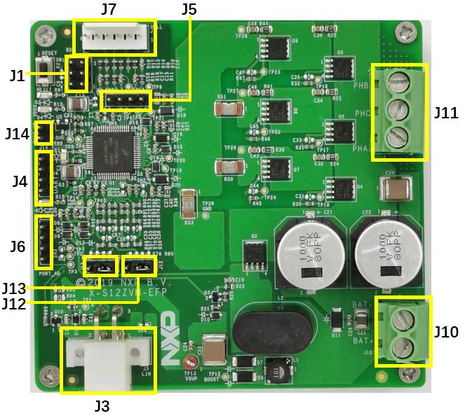
NXP Semiconductors

Contents
Chapter 1 RDB Introduction and Features.............................................................3

Chapter 2 Hardware System Block Diagram......................................................... 5

Chapter 3 RDB Sub Mdule Function Circuit Design Details.................................. 6

Chapter 4 Connector/Interface Overview.............................................................11

Chapter 5 Schematic and PCB Gerber File......................................................... 15

Chapter 6 BOM list...............................................................................................17

Chapter 7 Appendix A. Reference....................................................................... 21

                                S12ZVM EFP RDB Hardware User Guide, Rev. 0, March 2020
Supporting Information                                                                                        2 / 22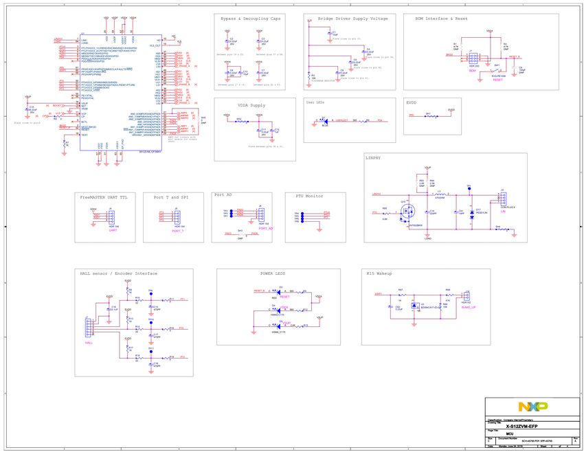
NXP Semiconductors
Chapter 1
RDB Introduction and Features
This user guide introduces hardware related information of PMSM fuel pump reference design of S12ZVM-EFP. It inlcudes the
hardware block diagram, schematics, connectors, interface, BOM and etc. BLDC and PMSM have become popular in automotive
industry. The application involving the fuel pump is one of the most popular application in the automotive industry. To accelerate
customer development period in BLDC or PMSM fuel pump application, NXP has developed the S12ZVM-EFP RDB. S12ZVM-
EFP is not only suitable for fuel pump application, but it can also be used in HVAC blower or other power range below 250W
BLDC and PMSM application.
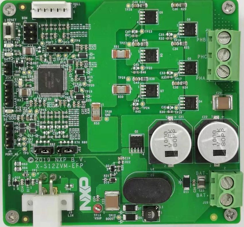
Figure 1. S12ZVM-EFP RDB
The RDB is based on NXP S12ZVM high-integrated (MCU, motor driver, power supply and other analog modules are integrated)
automotive-grade MCU and provides the following features:
S12ZVM EFP RDB Hardware User Guide, Rev. 0, March 2020
Supporting Information 3 / 22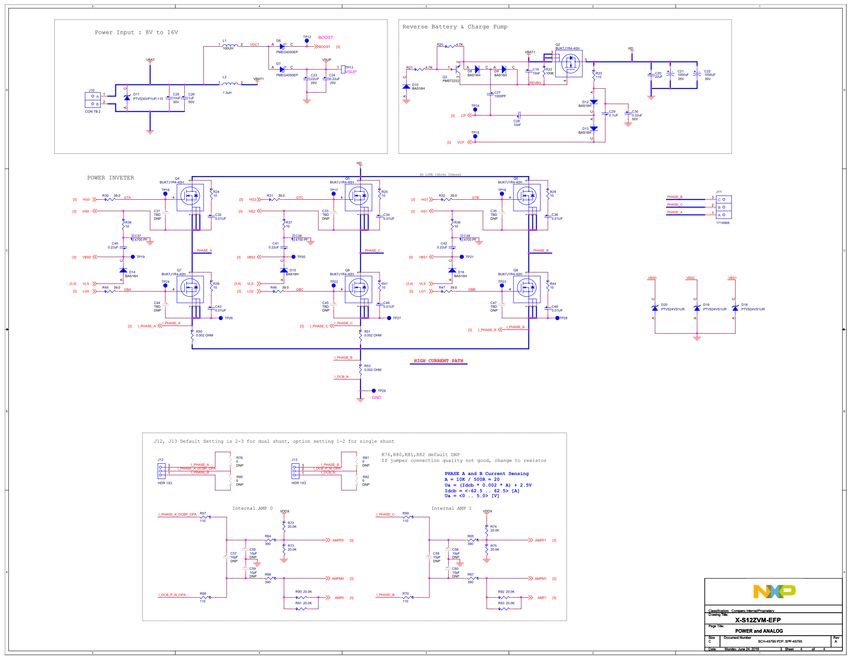
NXP Semiconductors
                                                                                                    RDB Introduction and Features

  • Support 12 V power supply system with up to 250 W automotive BLDC/PMSM motor control system
  • Implement two types of current sampling solutions:
      — Single shunt
      — Dual shunts
  • Support multiple diagnose and protection covering UV, OV, OT, OC, Short, Stall Detection, etc
  • Support speed/control commands from LIN/PWM
The following table provides a list and description of acronyms used throughout this document

Table 1. Acronyms and abbreviations

Abbreviation                                                   Description

RDB                                                            Reference Design Board

HW                                                             Hardware

SW                                                             Software

QSP                                                            Quick Start Package

POR                                                            Power-On Reset

BLDC                                                           Brushless Direct Current

PMSM                                                           Permanent-Magnet Synchronous Motor

                                   S12ZVM EFP RDB Hardware User Guide, Rev. 0, March 2020
Supporting Information                                                                                                     4 / 22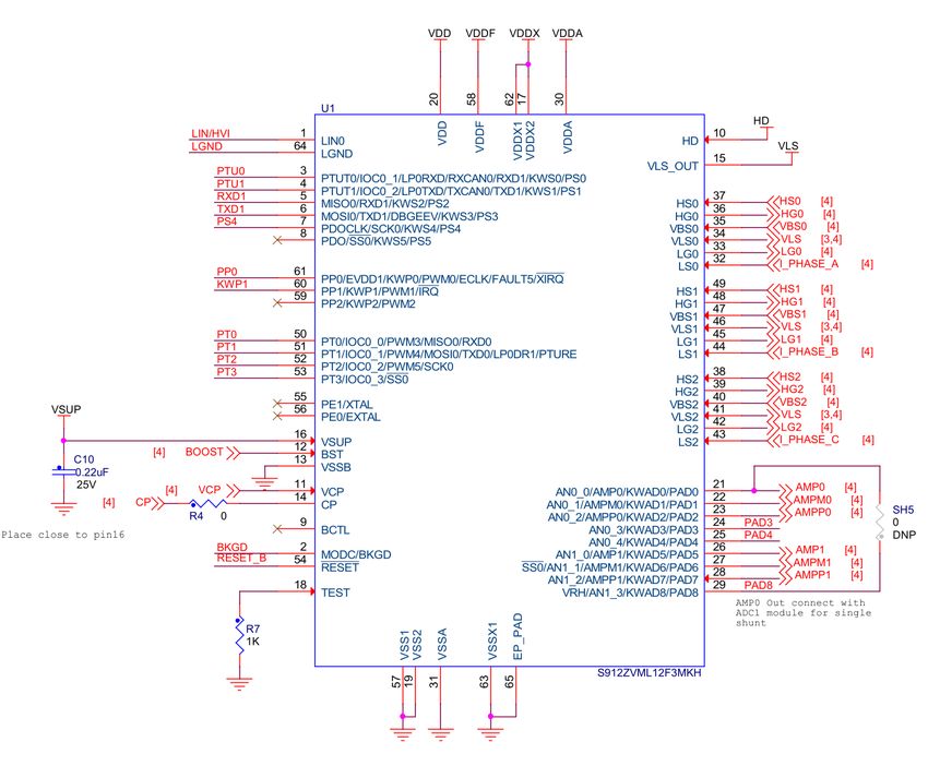
NXP Semiconductors

Chapter 2
Hardware System Block Diagram
This RDB is designed to deliver a total solution for BLDC or PMSM fuel pump application in 12 V automotive system.
To achieve the function features the 8~16V VBAT input is firstly connected in an anti-reverse protection circuit and get output of
VIN. The VIN then is connected to three phase inverter bridge and charge pump circuit. The charge pump circuit can pump the
input voltage to a higher voltage and make sure the reverse circuit can work correctly. VIN is also connected to boost circuit and
then to the VSUP PIN of S12ZVML128. If boost circuit is enabled, the input voltage can be down to 3.5 V. There are three shunts
in three phase inverter bridge circuit, two shunts are in the phase A and phase C leg, one shunt is in the minus bus to GND.
There are two jumper settings for single shunt and dual shunt switch, the default setting is dual shunt.
The RDB has Hall/Encoder interface for position sensor support. For debug purpose, not only BDM and FreeMASTER TTL (SCI)
are placed, but also the PTU monitor (PTU0/1/RE) is placed. Meanwhile, some other PINs, like Port AD and T, one SPI which
would be used are placed for reference.
The following is the RDB hardware system block diagram.

 Figure 2. The RDB hardware system block diagram

The main devices used in the RDB are:
  • S12ZVML128: High integrated automotive grade 16bit MCU using NVM+UHV technology. The chip integrated S12Z core
    based MCU, and 40 V analog components (VREG, GDU, LIN PHY), which make it suitable for single chip BLDC or PMSM
    control. Memory including 128K flash, 8K RAM, 512 B EEPROM all with ECC. The operating junction temperature can up
    to 175℃
  • BUK7J1R4-40H: N-channel FET with LFPAK56 (Power-SO8) package

                                    S12ZVM EFP RDB Hardware User Guide, Rev. 0, March 2020
Supporting Information                                                                                                      5 / 22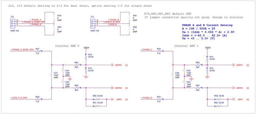
NXP Semiconductors

Chapter 3
RDB Sub Mdule Function Circuit Design Details
The RDB hardware sub-module function circuit design details are described in this chapter.

3.1 Power supply circuit
Power supply circuit includes two parts, one is “Power Input” and another is “Reverse Battery and Charge Pump”.
For “Power Input” portion, the details is shown in the following fgure. TVS D11 is used to power input protection. C25, C26 and
L2 are used for three phase bridge input filter. L1 and D6 are used for BOOST components and D7 for S12ZVM supply VSUP
protection and isolation.

 Figure 3. Power input circuit

For “Reverse Battery and Charge Pump” portion D12, D13, C28 and C29 are grouped as charge pump circuit which can make
sure the upper MOSFET can remain turned ON 100% during duty cycle. The same time, charge pump can supply a positive
gate-source voltage and turn the Q2 ON by using D8, D9, C27 and C19. R20, R21 and D10 are used to turn the Q2 OFF if the
battery is reverse connected.
C21 and C22 are 1000 uF, 35 V AL Capacitors which used to stable the voltage in three phase inverter bridge circuit for high
current application.

                                   S12ZVM EFP RDB Hardware User Guide, Rev. 0, March 2020
Supporting Information                                                                                                    6 / 22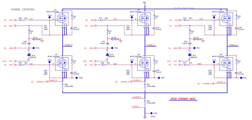
NXP Semiconductors
                                                                                    RDB Sub Mdule Function Circuit Design Details

 Figure 4. Reverse battery and charge pump circuit

3.2 MCU circuit
For S12ZVM MCU, refer to AN5207,add a 0.22 uF bypass capacitor for each VDD, VDDF, two VDDX pin, and place these
capacitors as close as possible to these pin, besides, a 10 uF bulk capacitor is used on the VDDX to keep its stable. For VDDA,
a 0.22 uF and a 1 uF capacitor are added. Refer to the following figure.

 Figure 5. MCU power supply circuit one

For VSUP pin, a 22 uF(C23) and two 0.22 uF(C10 and C24) are used for VSUP decouple and bulk. Refer to the following figure.

 Figure 6. MCU power supply circuit two

                                   S12ZVM EFP RDB Hardware User Guide, Rev. 0, March 2020
Supporting Information                                                                                                     7 / 22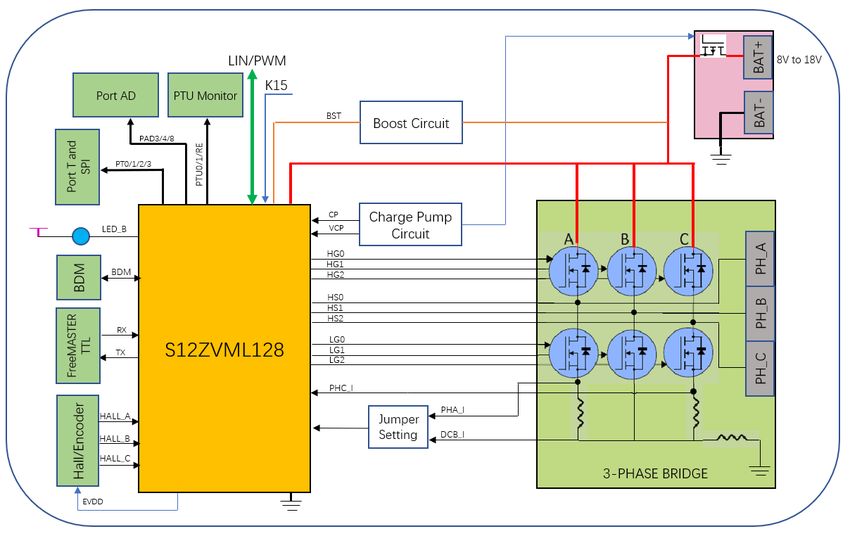
NXP Semiconductors
                                                                                    RDB Sub Mdule Function Circuit Design Details

EVDD is used for external supply, compared with VDDX, EVDD can be easily controlled (ON or OFF). EVDD has the function
for current monitor, so recommend EVDD for external hall sensor supply. Refer to the following figure.

 Figure 7. MCU power supply circuit three

S12ZVM MCU integrated S12Z based MCU, VREG, three phase motor driver, LIN PHY and some analog modules which simplify
the system design for motor control, especially for three phase BLDC and PMSM control.
From S12ZVML128 pin 32 to pin 49, these pins are used for three phase inverter driver. Pins 21 to 29 are used for dual shunt
or single shunt current sampling. Dual OPAMPs are integrated in GDU model which make S12ZVML128 very suitable for dual
shunt PMSM application. Dual shunt application has less current distortion than single shunt. .
EP_PAD is the exposed pad in the bottom of chip which is used for heat dispassion. The EP_PAD should connect to GND to
make sure the chip can work normally. Refer the following figure for more information.

 Figure 8. MCU function circuit one

Other portion of MCU interface are listed in the following figure.

 Figure 9. MCU function circuit two

For BDM interface and reset circuit is shown in the following figure.

                                     S12ZVM EFP RDB Hardware User Guide, Rev. 0, March 2020
Supporting Information                                                                                                     8 / 22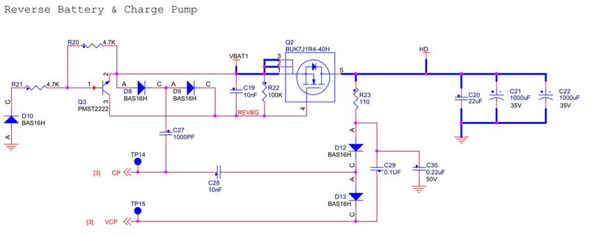
NXP Semiconductors
                                                                                         RDB Sub Mdule Function Circuit Design Details

 Figure 10. MCU BDM interface and RESET circuit

There are four LEDs indicators. D5 for VSUP indicator, D4 for VDDX indicator, D3 for reset indicator and D1 for user application.
Following figure shows more information.

 Figure 11. LEDs for power indicator and user

3.3 Three phase bridge and signal condition circuit
Six N-channel MOSFET (BUK7J1R4-40E) are used to construct three half-bridge power stage for three phase motor control.

 Figure 12. Power stage circuit

Two 2m shunt resistors(R50 and R51) are used for phase current sample by using dual shunt method. One 2mΩshunt resistor
R53 IS used for single shunt current sampling.
The voltage signal of the shunt is very small, so there is no need to amplify these small signals. It is due to the internal integrated
two OPAMPs, S12ZVML128 is suitable for both dual shunt and single shunt FOC.

                                     S12ZVM EFP RDB Hardware User Guide, Rev. 0, March 2020
Supporting Information                                                                                                           9 / 22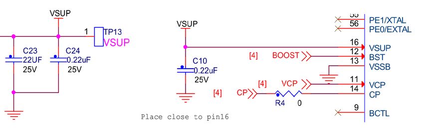
NXP Semiconductors
                                                                                      RDB Sub Mdule Function Circuit Design Details

 Figure 13. Phase current signal condition circuit

The signal condition circuit has two jumper settings. The default one is for dual shunt and another one is for single shunt. For
more information refer to the above figure.

3.4 LIN/HVI PHY communication circuit
LIN PHY is integrated in S12ZVML128. The motor ECU is used as LIN slave, so the pull up resistances are not positioned. If you
use the HVI PHY function then you can input the PWM (voltage as high as VBAT) to the MCU’s HVI pin by an inductance or
direct. For the PWM controlled ECU, the system needs to diagnose the signal output though the PWM line. One PWM line
achieves both the function, it receives the PWM input and feedback the output. The feedback uses the PT0 to control the Q10
and Pull the PWM line to low, the PWM sender samples the level of PWM line and release the control to S12ZVML128.
The following figure shows the circuit of LIN/HVI PHY.

 Figure 14. LIN/HVI PHY circuit

                                    S12ZVM EFP RDB Hardware User Guide, Rev. 0, March 2020
Supporting Information                                                                                                      10 / 22
NXP Semiconductors
Chapter 4
Connector/Interface Overview
The RDB connector function and pin allocation are described in this chapter.
Figure 15. The connector distribution on the RDB
Power input connector, the RDB is designed for 12 V system, so the recommend VBAT input voltage range is 8 V DC to 16 V DC.
Connector pin function
J10-1 VBAT+
J10
J10-2 VBAT-
3-phase motor connector.
Connector pin function
J11-1 PHA
J11 J11-2 PHC
J11-3 PHB
S12ZVM EFP RDB Hardware User Guide, Rev. 0, March 2020
Supporting Information 11 / 22NXP Semiconductors
Connector/Interface Overview
Debug interface connector, the RDB debugger BDM port is routed to J1.
Connector pin function
J1-1 BKGD
J1-2 GND
J1-3 NC
J1
J1-4 RESET_B
J1-5 NC
J1-6 VDDX
Hall sensor connector.
Connector pin function
J7-1 EVDD
J7-2 GND
J7-3 HALL_A
J7
J7-4 HALL_B
J7-5 HALL_C
J7-6 NC
FreeMASTER UART TTL communication connector.
Connector pin function
J4-1 VDDX
J4-2 TXD1
J4
J4-3 RXD1
J4-4 GND
LIN communication connector.
Connector pin function
J3 J3-1 GND
Table continues on the next page...
S12ZVM EFP RDB Hardware User Guide, Rev. 0, March 2020
Supporting Information 12 / 22NXP Semiconductors
Connector/Interface Overview
Table continued from the previous page...
Connector pin function
J3-2 GND
J3-3 NC
J3-4 LIN
K15 Line interface.
Connector pin function
J14-1 K15 line
J14
J14-2 GND
Port AD interface for extended use.
Connector pin function
J6-1 PAD3
J6-2 PAD4
J6
J6-3 PAD8
J6-4 GND
Port T and SPI interface for extended use.
Connector pin function
J5-1 PT3/SS0
J5-2 PT2/SCK0
J5
J5-3 PT1/MOSI0
J5-4 PT0/MISO0
Dual shunt and single shunt selection jumper setting.
S12ZVM EFP RDB Hardware User Guide, Rev. 0, March 2020
Supporting Information 13 / 22NXP Semiconductors
Connector/Interface Overview
Function Connector pin
Dual shunt setting J12 Position J12-2 and J12-3
(Default Setting) J13 Position J13-2 and J13-3
J12 Position J12-1 and J12-2
Single shunt setting
J13 Position J13-1 and J13-2
S12ZVM EFP RDB Hardware User Guide, Rev. 0, March 2020
Supporting Information 14 / 22NXP Semiconductors
Chapter 5
Schematic and PCB Gerber File
The complete schematic and PCB gerber files of the RDB are included in the QSP, you can download it from swww.nxp.com.
S12ZVM EFP RDB Hardware User Guide, Rev. 0, March 2020
Supporting Information 15 / 22NXP Semiconductors
Schematic and PCB Gerber File
S12ZVM EFP RDB Hardware User Guide, Rev. 0, March 2020
Supporting Information 16 / 22NXP Semiconductors
Chapter 6
BOM list
The followin table provides the list if BOM for RDB.
Table 2. S12ZVM-EFP board BOM
Part reference Quantity Value DESCRIPTION Manufacturer
C1,C13,C25 3 10uF CAP CER 10uF 35V 10% X7R 1210 MURATA
C2-C7,C9-C11,C24,C40-
13 0.22uF CAP CER 0.22uF 25V 10% X7R 0603 KEMET
C42
CAP CER 100pF 50V 5% C0G AEC-
C8 1 100pF MURATA
Q200 0402
CAP CER 1uF 50V 10% X5R AEC-
C12,C26 2 1uF TDK
Q200 0603
C14 1 220PF CAP CER 220PF 50V 5% C0G 0603 AVX
C15,C17,C18 3 470PF CAP CER 470PF 50V 10% X7R 0603 AVX
C16,C29 2 0.1UF CAP CER 0.1UF 50V 10% X7R 0603 AVX
C19,C28 2 10nF CAP CER 0.01UF 50V 5% X7R 0603 AVX
C20 1 22uF CAP CER 22uF 50V X7S 20% 2220 TDK
NIPPON CHEMI-
CAP ALEL 1000uF 35V 20% --- AEC-
C21,C22 2 1000uF CON
Q200 SMT
CORPORATION
C23 1 22UF CAP CER 22.0UF 25V 20% X7R 2220 TDK
C27 1 1000PF CAP CER 1000PF 50V 5% C0G 0603 MURATA
CAP CER 0.22uF 50V 10% X7R AEC-
C30,C62 2 0.22uF Murata
Q200 0603
C31,C33,C35,C44,C45,C4 0603 Place holder -Layout element only
6 TBD N.A
7 - NO PART TO ORDER
C32,C34,C36,C43,C46,C4
6 0.01UF CAP CER 0.01UF 100V 5% X7R 0805 KEMET
8
C37-C39 3 4700 PF CAP CER 4700PF 50V 5% X7R 0603 AVX
C55-C60 6 10pF CAP CER 10PF 50V 10% X7R 0603 AVX
C61 1 15PF CAP CER 15PF 50V 5% C0G 0603 YAGEO AMERICA
Table continues on the next page...
S12ZVM EFP RDB Hardware User Guide, Rev. 0, March 2020
Supporting Information 17 / 22NXP Semiconductors
BOM list
Table 2. S12ZVM-EFP board BOM (continued)
Part reference Quantity Value DESCRIPTION Manufacturer
D1 1 BLUE LED BLUE SGL 20MA SMT 0805 LITE ON
D3 1 RED LED RED SGL 25MA 0805 DIALIGHT
AVAGO
D4 1 HSMG-C170 LED GREEN SGL 2.2V 20MA 0805
TECHNOLOGIES
AVAGO
D5 1 HSMA_C170 LED AMBER SGL 25MA SMT
TECHNOLOGIES
DIODE SCH RECT 5A 40V AEC-Q101
D6,D7 2 PMEG4050EP NEXPERIA
SOD128
D8-D10,D12-D16 8 BAS16H DIODE SW 200MA 75V SOD323 On Semiconductor
PTVS30VP1UP,11
D11 1 DIODE TVS 600W AEC-Q101 SOD-128 NEXPERIA
5
DIODE ESD PROTECTION 23KV AEC-
D17 1 PESD1LIN NEXPERIA
Q101 SOD323
DIODE TVS 400W 24V AEC-Q101
D18-D20 3 PTVS24VS1UR NEXPERIA
SOD123W
HDR 2X3 TH 100MIL CTR 344H AU WURTH
J1 1 HDR 2X3
118L ELEKTRONIK
CON 2X2 PLUG SHRD RA TH 4.2MM
J3 1 CON PLUG 4 Molex
CTR 394H AU 138L
WURTH
J4-J6 3 HDR 1X4 HDR 1X4 TH 2.54MM SP 344H AU 118L
ELEKTRONIK
J7 1 HEADER 1X6 HDR 1X6 TH 100MIL SP 460H SN MOLEX
CON 1X2 TB TH 6.35MM SP 846H SN PHOENIX
J10 1 CON TB 2
201L CONTACT
CON 1X3 TB TH 6.35MM SP 847H -- PHOENIX
J11 1 1714968
201L CONTACT
WURTH
J12,J13 2 HDR 1X3 HDR 1X3 TH 2.54MM SP 344H AU 118L
ELEKTRONIK
WURTH
J14 1 HDR1X2 HDR 1X2 TH 100MIL SP 342H AU 118L
ELEKTRONIK
IND PWR 100UH@100KHZ 420MA
L1 1 100UH TDK
20% SMT
Table continues on the next page...
S12ZVM EFP RDB Hardware User Guide, Rev. 0, March 2020
Supporting Information 18 / 22NXP Semiconductors
BOM list
Table 2. S12ZVM-EFP board BOM (continued)
Part reference Quantity Value DESCRIPTION Manufacturer
NIPPON CHEMI-
L2 1 1.3uH IND CHK 1.3uH@20kHz 30A -- TH CON
CORPORATION
IND FER BEAD 470OHM@100MHZ
L3 1 470OHM MURATA
500MA 25% 0603
TRAN NMOS 40V 120A AEC-Q101
Q2,Q4-Q9 7 BUK7J1R4-40H NEXPERIA
LFPAK56
TRAN BJT NPN PWR 600MA 40V AEC-
Q3 1 PMST2222 NEXPERIA
Q101 SOT-323
TRAN NMOS 310mA 60V AEC-Q101
Q10 1 2N7002BKW NEXPERIA
SOT323
VISHAY
R1,R2,R20,R21 4 4.7K RES MF 4.7K 1/10W 5% 0603 INTERTECHNOL
OGY
VISHAY
RES MF 10K 1/10W 1% AEC-Q200
R3,R89 2 10K INTERTECHNOL
0603
OGY
R4,R11,R16,R19,R76,R80 RES MF ZERO OHM 1/10W -- AEC-
10 0 PANASONIC
-R82,SH3,SH5 Q200 0603
R6,R9,R12 3 560 RES MF 560 1/10W 5% 0603 YAGEO AMERICA
R7,R8,R13,R17,R87 5 1K RES MF 1K 1/10W 1% AEC-Q200 0603 YAGEO
VISHAY
RES MF 33 OHM 1/10W 5% AEC-
R10,R14,R18 3 33 INTERTECHNOL
Q200 0603
OGY
RES MF 2.40K 1/10W 1% AEC-Q200
R15 1 2.4K KOA SPEER
0603
R22 1 100K RES MF 100K 1/10W 5% 0603 BOURNS
RES MF 110 OHM 1/8W 1% AEC-
R23,R57,R59,R68,R70 5 110 KOA SPEER
Q200 0603
R24,R25,R29,R36-
9 10 RES MF 10.0 OHM 1/8W 1% 0805 BOURNS
R39,R41,R44
WALSIN
R30-R32,R45-R47 6 39.0 RES MF 39.0 OHM 1/10W 1% 0603 TECHNOLOGY
CORP.
Table continues on the next page...
S12ZVM EFP RDB Hardware User Guide, Rev. 0, March 2020
Supporting Information 19 / 22NXP Semiconductors
BOM list
Table 2. S12ZVM-EFP board BOM (continued)
Part reference Quantity Value DESCRIPTION Manufacturer
ISABELLENH¨¨TT
RES PWR 0.002 OHM 5W 1% AEC-
R50,R51,R53 3 0.002 OHM E HEUSLER
Q200 2512
GMBH & CO. KG
RES MF 390 OHM 1/8W 1% AEC-
R64-R67 4 390 KOA SPEER
Q200 0603
RES MF 20.0K 1/10W 1% AEC-Q200
R72-R75,R90-R93 8 20.0K KOA SPEER
0603
R83,R84 2 2.0K RES MF 2.0K 1/8W 5% 0805 PANASONIC
VISHAY
RES MF 6.8K 1/8W 0.1% AEC-Q200
R85 1 6.8K INTERTECHNOL
0603
OGY
VISHAY
RES MF 47K 1/10W 1% AEC-Q200
R88 1 47K INTERTECHNOL
0603
OGY
ZERO OHM CUT TRACE 0603 PADS; LAYOUT
SH1,SH2,SH4 3 0
NO PART TO ORDER ELEMENT ONLY
SW1 1 EVQ-PE105K SW SPST NO 0.05A 12V SMD PANASONIC
TP1-TP12,TP14- TEST POINT PAD 40MIL DIA SMT, NO NOTACOMPONE
27 TPAD_040
TP24,TP26-TP29 PART TO ORDER NT
KEYSTONE
TP13 1 TEST_POINT TEST POINT RED 70X220 MIL TH
ELECTRONICS
NXP
S912ZVML12F3M IC SoC (MCU + LIN + GDU) 16-BIT S12Z
U1 1 SEMICONDUCTO
KH 128K FLASH 6K RAM LQFP64
RS
VISHAY
BZX84C4V7-
U2 1 DIODE ZNR 4.7V 300mW 5% SOT23 INTERTECHNOL
E3-08
OGY
S12ZVM EFP RDB Hardware User Guide, Rev. 0, March 2020
Supporting Information 20 / 22NXP Semiconductors
Chapter 7
Appendix A. Reference
1.AN5207, Hardware Design Guidelines for S12ZVM Microcontrollers (REV 2)
2. MC9S12ZVM Family - Reference Manual and Datasheet (REV 2.13)
S12ZVM EFP RDB Hardware User Guide, Rev. 0, March 2020
Supporting Information 21 / 22How To Reach Us Information in this document is provided solely to enable system and software implementers to
use NXP products. There are no express or implied copyright licenses granted hereunder to
Home Page:
design or fabricate any integrated circuits based on the information in this document. NXP
nxp.com reserves the right to make changes without further notice to any products herein.
Web Support: NXP makes no warranty, representation, or guarantee regarding the suitability of its products for
nxp.com/support any particular purpose, nor does NXP assume any liability arising out of the application or use
of any product or circuit, and specifically disclaims any and all liability, including without limitation
consequential or incidental damages. “Typical” parameters that may be provided in NXP data
sheets and/or specifications can and do vary in different applications, and actual performance
may vary over time. All operating parameters, including “typicals,” must be validated for each
customer application by customer's technical experts. NXP does not convey any license under
its patent rights nor the rights of others. NXP sells products pursuant to standard terms and
conditions of sale, which can be found at the following address: nxp.com/
SalesTermsandConditions.
While NXP has implemented advanced security features, all products may be subject to
unidentified vulnerabilities. Customers are responsible for the design and operation of their
applications and products to reduce the effect of these vulnerabilities on customer’s applications
and products, and NXP accepts no liability for any vulnerability that is discovered. Customers
should implement appropriate design and operating safeguards to minimize the risks associated
with their applications and products.
NXP, the NXP logo, NXP SECURE CONNECTIONS FOR A SMARTER WORLD, COOLFLUX,
EMBRACE, GREENCHIP, HITAG, I2C BUS, ICODE, JCOP, LIFE VIBES, MIFARE, MIFARE
CLASSIC, MIFARE DESFire, MIFARE PLUS, MIFARE FLEX, MANTIS, MIFARE ULTRALIGHT,
MIFARE4MOBILE, MIGLO, NTAG, ROADLINK, SMARTLX, SMARTMX, STARPLUG, TOPFET,
TRENCHMOS, UCODE, Freescale, the Freescale logo, AltiVec, C‑5, CodeTEST, CodeWarrior,
ColdFire, ColdFire+, C‑Ware, the Energy Efficient Solutions logo, Kinetis, Layerscape, MagniV,
mobileGT, PEG, PowerQUICC, Processor Expert, QorIQ, QorIQ Qonverge, Ready Play,
SafeAssure, the SafeAssure logo, StarCore, Symphony, VortiQa, Vybrid, Airfast, BeeKit,
BeeStack, CoreNet, Flexis, MXC, Platform in a Package, QUICC Engine, SMARTMOS, Tower,
TurboLink, UMEMS, EdgeScale, EdgeLock, eIQ, and Immersive3D are trademarks of NXP B.V.
All other product or service names are the property of their respective owners. AMBA, Arm,
Arm7, Arm7TDMI, Arm9, Arm11, Artisan, big.LITTLE, Cordio, CoreLink, CoreSight, Cortex,
DesignStart, DynamIQ, Jazelle, Keil, Mali, Mbed, Mbed Enabled, NEON, POP, RealView,
SecurCore, Socrates, Thumb, TrustZone, ULINK, ULINK2, ULINK-ME, ULINK-PLUS, ULINKpro,
µVision, Versatile are trademarks or registered trademarks of Arm Limited (or its subsidiaries) in
the US and/or elsewhere. The related technology may be protected by any or all of patents,
copyrights, designs and trade secrets. All rights reserved. Oracle and Java are registered
trademarks of Oracle and/or its affiliates. The Power Architecture and Power.org word marks
and the Power and Power.org logos and related marks are trademarks and service marks
licensed by Power.org.
© NXP B.V. 2020. All rights reserved.
For more information, please visit: http://www.nxp.com
For sales office addresses, please send an email to: salesaddresses@nxp.com
Date of release: March 2020
Document identifier: S12ZVMEFPHUGYou can also read