Direct observation of the perpendicular shape anisotropy and thermal stability of STT-MRAM nano-pillars examined by off-axis electron holography
←
→
Page content transcription
If your browser does not render page correctly, please read the page content below
2170                                                                                                                        Microsc. Microanal. 27 (Suppl 1), 2021
            doi:10.1017/S1431927621007819                                                                                               © Microscopy Society of America 2021

            Direct observation of the perpendicular shape anisotropy and thermal stability of
            STT-MRAM nano-pillars examined by off-axis electron holography
            Trevor Almeida1, Steven Lequeux2, Alvaro Palomino2, Nuno Caçoilo2, Aurélien Massebouef2, Richard Sousa2,
            Olivier Fruchart2, Ioan-Lucian Prejbeanu2, Bernard Dieny3 and David Cooper4
            1
             Univ. Grenoble Alpes, CEA, Leti, F-38000 Grenoble, France., France, 2Univ Grenoble Alpes, CEA, CNRS,
            Grenoble INP, SPINTEC, 38000 Grenoble, France., France, 3Univ Grenoble Alpes, CEA, CNRS, Grenoble
            INP, SPINTEC, 38000 Grenoble, France., Grenoble, France, 4Univ Grenoble Alpes, CEA, LETI, France

            Magnetic random-access memory (MRAM) is a non-volatile memory based on the storage of one bit of
            information by a ferromagnetic memory carrier. In particular, spin-transfer torque (STT) MRAM has attracted
            great interest by the microelectronics industry as a replacement for embedded FLASH memory. Out-of-plane
            STT-MRAM involves the use of a magnetic tunnel junction (MTJ) comprising an MgO tunnel barrier (1 – 1.5
            nm) sandwiched between two thin perpendicularly-magnetized layers: one magnetically-pinned reference
            layer, and one switchable storage layer. The electrical resistance of the MTJ changes significantly when the
            layers are magnetized in parallel and antiparallel states, providing a system of readable / writable ‘0’ or ‘1’
            binary information. The areal bit density of modern STT-MRAM can be improved further by reducing the in-
            plane size of the MTJ, which however may reduce the thermal stability of the storage layer. One solution is to
            increase the storage layer thickness to larger than its diameter so that its out-of-plane aspect ratio provides
            additional thermal stability through perpendicular shape anisotropy (PSA). Previous studies have shown that
            the PSA-STT-MRAM are indeed highly thermally stable, making them an exciting solution to downsize
            scalability of STT-MRAM at sub-20 nm technology nodes1,2. However, our knowledge of the thermal stability
            of these STT-MRAM nano-pillars is often indirect, relying on magnetoresistance measurements and
            micromagnetic modelling. In order to understand fully their thermomagnetic behavior, it is necessary to
            examine the effect of temperature directly. The advanced transmission electron microscopy (TEM) technique
            of off-axis electron holography allows imaging of magnetization within nano-scale materials. Here, we use
            electron holography to image the micromagnetic configuration of the nano-pillars in presence of PSA and to
            visualize its thermal stability through in-situ heating.

            A series of nano-pillar arrays were investigated: 1) etched Co / FeCoB / Co stacks; 2) Co nano-pillars grown
            within pores of a structured substrate surface; and 3) etched FeCoB / NiFe stacks. TEM samples were prepared
            by depositing a protective layer (~ 1 µm) of resin on the array prior to a protective Pt layer being deposited by
            the focused ion beam (FIB). Cross-sectional TEM lamellae were transferred to Omniprobe copper slots and
            thinned to < 100 nm (sample 2) or ~ 300 nm (samples 1 & 3) using conventional FIB methods. The protective
            resin layer was removed by plasma etching and the remaining Pt layer was broken with the
            micromanipulator. Scanning TEM (STEM) imaging was performed using a probe-CS-corrected Thermo
            Fisher Titan TEM at 200kV, whilst energy dispersive X-ray (EDX) spectroscopy provided chemical analysis.
            Off-axis electron holograms were acquired under field-free conditions in Lorentz mode on a Gatan OneView
            4K camera using a Thermo Fisher Titan TEM equipped with an image-CS corrector and an electron biprism.
            The magnetization states of the nano-pillars were visualized through separation of the magnetic contribution
            to the phase shift from the mean inner potential (MIP), achieved by tilting and applying the strong field of the
            objective lens (< 1.5T) to reverse their magnetism. In-situ heating up to 250°C was performed using a Gatan
            heating holder under field-free magnetic conditions. The heating was repeated and the magnetic reversal was
            performed at each temperature interval to isolate the MIP, and subtracted from the first heating to reconstruct
            the thermomagnetic behavior of the nano-pillars3,4.

            Figure 1 presents magnetic induction maps reconstructed from electron holograms acquired from samples 1 &
            2. The magnetic induction map of sample 1 (Fig. 1a) reveals the magnetic contours flowing through the multi-

Downloaded from https://www.cambridge.org/core. IP address: 46.4.80.155, on 07 Oct 2021 at 23:38:21, subject to the Cambridge Core terms of use, available at
https://www.cambridge.org/core/terms. https://doi.org/10.1017/S1431927621007819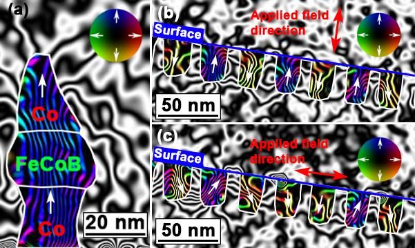
Microsc. Microanal. 27 (Suppl 1), 2021 2171
layered Co (20 nm) / FeCoB (20 nm) / Co (25 nm) nano-pillar in a direction parallel to its long axis (indicated
by white arrows), confirming its out-of-plane PSA. Fig. 1b-c presents magnetic induction maps of arrays of
Co nano-pillars (~ 20 nm diameter, ~ 40 nm height) grown in pores of the substrate (sample 2). During the
magnetic reversal process in Fig. 1b, a large component of the field is applied in a direction parallel to the
elongated axis of the nano-pillars (red arrow). Hence, the magnetization is observed to favor this axis with
adjacent nano-pillars being magnetized in parallel and antiparallel directions, perpendicular to the plane of the
surface. In Fig. 1c, a large component of the field is applied parallel to the plane of the surface (red arrow) and
whilst some nano-pillars retain their magnetization along their major axis, it is clear that a few nano-pillars
relax into more transverse or perpendicular directions, generally flowing from left to right. In both cases, the
stray fields reveal interactions between the nano-pillars and are suggested to restrict their magnetic states from
relaxing along their elongated axis and in the same direction.
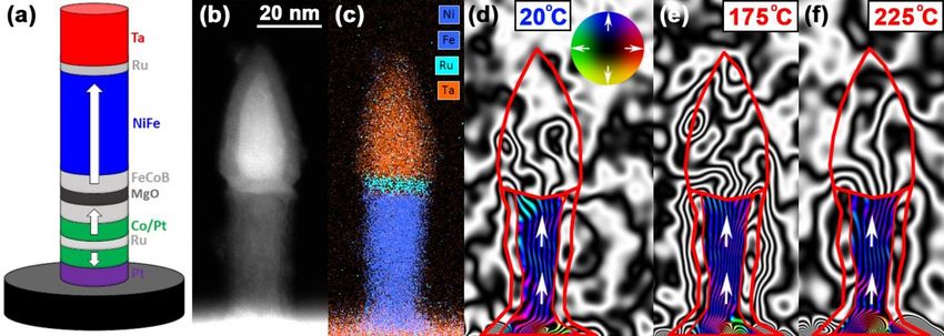
Figure 2 presents the morphology, chemical composition and thermal stability of an individual nano-pillar
from sample 3. The schematic of Fig. 2a displays the full stack of the MTJ cell, where the thick NiFe section
is deposited on a conventional stack to provide the PSA in the storage layer2. The STEM image (Fig. 2b) and
EDX map (Fig. 2c) reveal that the NiFe section of nano-pillar is 60 nm high with a diameter of ~ 20 nm, and
is separated from the hard Ta mask by a Ru layer. The magnetic induction map of Fig. 2d shows that the
magnetization lies along the elongated axis of the NiFe section at 20°C, as indicated by the white arrows.
Magnetic induction maps acquired during in-situ heating to 175°C (Fig. 2d) and 225°C (Fig. 2e) shows the
nano-pillar to retain this direction of magnetization at elevated temperatures. This confirms that the high-
aspect-ratio NiFe nano-pillar provides out-of-plane PSA that is thermally stable up to 225°C, and hence
resistant to thermal variations during operation.
Figure 1. (a) Magnetic induction map of the multi-layered Co / FeCoB / Co nano-pillar (sample 1) showing
the magnetization flowing along its elongated (i.e. vertical) axis. (b,c) Magnetic induction maps of the Co
nano-pillars grown in pores of the substrate (sample 2), with a large component of the field applied in directions
(b) perpendicular; and (c) parallel to the substrate surface during the magnetic reversal process (denoted by
red arrows). The contour spacing is 0.042 rad for all the magnetic induction maps, and the magnetization
direction is shown using white arrows, as depicted in the color wheels.
Downloaded from https://www.cambridge.org/core. IP address: 46.4.80.155, on 07 Oct 2021 at 23:38:21, subject to the Cambridge Core terms of use, available at https://www.cambridge.org/core/terms.
https://doi.org/10.1017/S1431927621007819
2172                                                                                                                       Microsc. Microanal. 27 (Suppl 1), 2021

            Figure 2. (a) Schematic of a PSA-STT-MRAM MTJ cell with a 60 nm NiFe storage layer, where the white
            arrows denote the expected magnetic easy axis2. (b) STEM image of a first PSA pillar with a diameter of ~
            20nm; and (c) the associated EDX chemical map showing the elemental distribution of Ta (red), Ni/Fe (blue)
            and Ru (turquoise). (d-f) Magnetic induction maps reconstructed from electron holograms acquired during in-
            situ heating at (d) 20°C; (e) 175°C; and (f) 225°C. The contour spacing is 0.042 rad for all the magnetic
            induction maps, and the magnetization direction is shown using white arrows, as depicted in the color wheel.

            References
            [1] N. Perrissin et al., Nanoscale 10, 12187-12195 (2018).
            [2] S. Lequeux et al., Nanoscale 12, 6378-6384, (2020).
            [3] T. P. Almeida et al., Geophys. Res. Lett. 43, 8426–8434 (2016).
            [4] T. P. Almeida et al., Sci. Adv., 2 (4), e1501801 (2016).

Downloaded from https://www.cambridge.org/core. IP address: 46.4.80.155, on 07 Oct 2021 at 23:38:21, subject to the Cambridge Core terms of use, available at https://www.cambridge.org/core/terms.
https://doi.org/10.1017/S1431927621007819
You can also read


