DN3PD1 Original Instruction Manual valid for ID-No: 33PD02 - Safety switchgear to monitor the speed of three-phase and single-phase motors without ...
←
→
Page content transcription
If your browser does not render page correctly, please read the page content below
DN3PD1
                                   Original Instruction Manual
                                      valid for ID-No: 33PD02

Safety switchgear
to monitor the speed of three-phase and
single-phase motors without sensor

                                                   wir sind sicherheit.
EU-Konformitätserklärung
EC-Declaration of Conformity
DINA Elektronik GmbH
Esslinger Str. 84
72649 Wolfschlugen
Germany
Phone +49 7022 95170
Fax      +49 7022 9517700
info@dina.de
www.dina.de

Wir erklären, dass folgendes Produkt die einschlägigen Harmonisierungsrechtsvorschriften der Union erfüllt.
We declare that the following product is in conformity with the relevant Union harmonisation legislation.
Produkt/product                                                  Beschreibung/description
DN3PD1                                                           Sicherheitsschaltgerät zur sensorlosen Drehzahlüberwachung
                                                                 bei Drei- und Einphasen Motoren
                                                                 Safety switchgear unit to monitor the speed of 3-phases and
                                                                 single phase motors without sensor

EU-Richtlinien/EC- directives                                    Angewandte Normen/Applied standards
2006/42/EG Maschinenrichtlinie/Machinery-Directive               EN ISO 13849-1:2015
2014/30/EU EMV-Richtlinie/EMC-Directive                          IEC 62061:2015
2011/65/EU RoHS Richtlinie/RoHS-Directive                        IEC 61800-5-2:2016
                                                                 IEC 61508: Parts 1-7:2010
                                                                 EN 50178: 1997
                                                                 EN 60204-1:2006 + A1:2009 + AC:2010
                                                                 EN 60947-5-1:2010
                                                                 EN 61326-1 :2013
                                                                 EN 61326-3-1:2008 + Entwurf 2015 SIL3

                                                                 GS-ET-20: 2016-10

Notifizierte Stelle/notified Body                                EG Baumusterprüfbescheinigung/EC Type-Examination certifi-
                                                                 cate
TÜV Rheinland Industrie Service GmbH                             Reg.-Nr./No.: 01/205/5650.01/18
Am Grauen Stein
51105 Köln
Germany

NB 0035

Wolfschlugen, 24.07.2018

Dirar Najib
Geschäftsführer/CEO

Content

21-06-09 / 33pd02-V0743.3                                                                                                      3
DN3PD1
Inhaltsverzeichnis
1 Intended Use 6
Approvals 6
Safety parameters 6
Ordering data 6
2 Safety regulations 7
3 Important information and validation 7
4 Function description 8
Switching threshold 8
Start-up monitoring 8
Minimum switch-off time 8
Acknowledge function 8
Functional diagram 9
Schematic, operating element and display 10
Terminal description 10
5 Applications 11
Motor with frequency converter 11
Motor with star-delta circuit 11
Single-phase motor 11
Servo motor 11
6 Mounting and removal 11
Wiring 12
Commissioning 12
Example of application 12
7 Parameterization of the switching thresholds 13
Important notes for parameterization 13
Table of frequencies 13
Configuration of the switching threshold and acknowledgement 14
Example for configuration 15
8 Diagnostics 16
Error report 16
9 Technical data 18
Ambient conditions 18
Input data 18
Output data 18
General data 18
Connection data 18
Relay load curve 19
10 Dimensions 19
4 21-06-09 / 33pd02-V0743.3.3DN3PD1
Always read the additional applicable online documentation before working on/with the safety switchgear.
Make sure you always work with the valid documentation. This is available online at
http://www.dina.de/downloads/
Dispose of the device according to the national environmental regulations.
Symbol and Notes:
WARNING
Observe the safety regulations and installation notes in the corresponding section.
INFO
Observe the notes in the corresponding section.
Version overview / Change history
Version Date valid for ID-No Innovations / changes
0743 2018-12-06 33PD02
0743.3 2020-06-16 33PD02 Error message if f > 800Hz
0743.3 2021-06-09 33PD02 Limitations when using servomotors
21-06-09 / 33pd02-V0743.3 5DN3PD1
Intended Use
1 Intended Use
Safety switchgear to monitor the speed of three-phase and single-phase motors without sensor.
Two speed thresholds are possible: minimum speed and maximum speed.
The unit meets Cat. 4/ PL e acc. to ISO 13849-1, SIL (CL) 3 acc. to IEC 62061 and IEC 61508.
Usage in safety current circuit according to VDE 0113 T.1
Approvals
Safety parameters
The unit meets Cat. 4/ PL e and SIL (CL) 3.
Parameter Value Note
PFH 1,56 E-09 1/h 1,6 % von SIL 3
MTTFd 553 a HIGH
DCavg 95% (HIGH)
table 1-1: Safety parameters
Ordering data
Description Type ID-No.:
Speed monitoring, sensorless 0-600Hz, 2 contact outputs,
DN3PD1 33PD02-01
start-up monitoring, switch-off time 01
Speed monitoring, sensorless 0-600Hz, 2 contact outputs,
DN3PD1 33PD02-02
start-up monitoring, switch-off time 02
6 21-06-09 / 33pd02-V0743.3.3DN3PD1
Safety regulations
2 Safety regulations
The device may only be installed and commissioned by an electrician or trained persons who are familiar with these
operating instructions and the applicable regulations regarding work safety and accident prevention.
Observe the VDE, EN and local regulations, particularly with respect to the protective measures.
Failure to observe the regulations may result in death, severe bodily injury or extensive property damage.
For emergency-stop applications, either the integrated function for restart interlock must be used or automatic re-
starting of the machine must be prevented by means of a higher-level control.
During transport, storage and operation adhere to the conditions specified in EN 60068-2-1, 2-2!
Unauthorized modifications shall render any warranty null and void. Dangers may thereby arise that could result in
severe injuries or even death.
Install the device in a control cabinet with a protection class of at least IP54! Dust and moisture may otherwise re-
sult in impaired functions. Installation in a control cabinet is mandatory.
Ensure adequate protection circuits at output contacts for capacitive and inductive loads!
The device is to be installed taking into account the distances required per DIN EN 50274, VDE 0660-514.
During operation, switching devices carry dangerous voltage. Do not remove protective covers.
Replace the device after the first malfunction.
Properly dispose of the device at the end of its service life.
If these regulations are not adhered to or in the event of improper use, DINA Elektronik GmbH accepts absolutely
no liability for the resulting property damages or personal injury.
Save this product information!
3 Important information and validation
The product described here was developed to perform safety-related functions as part of a complete system.
The complete system consists of sensors, evaluation and message units as well as concepts for safe shutdowns.
It is the responsibility of the manufacturer of a system or machine to ensure the proper overall function.
The manufacturer of the system is required to test and to document the effectiveness of the implemented safety
concept within the complete system.
In this case, it must be checked whether the release contacts open when exceeding or falling below the thresholds.
This verification is to be performed after every modification to the safety concept or to safety parameters.
DINA Elektronik is not in the position to guarantee the properties of a complete system that was not designed by
DINA.
DINA Elektronik GmbH also accepts no liability for recommendations that are given or implied by the following de-
scription.
No new guarantee, warranty or liability claims that extend beyond DINA's general delivery conditions can be de-
rived on the basis of the following description.
To avoid EMC disturbances, the physical environmental and operating conditions at the installation location of the
product must comply with section EMC of DIN EN 60204-1.
When using contact outputs, the safety function must be requested once a day at PL e and once a year at PL d ac-
cording to IEC 61800-5-2.
Observe the general technical data at the end of this operating manual.
21-06-09 / 33pd02-V0743.3 7DN3PD1
Function description
4 Function description
The two-channel evaluation unit of the safety switchgear module measures the frequency of the effective rotating field of
the motor at the measuring terminals L1, L2, L3.
If the parameterized switching threshold frequencies are exceeded or undershot (V-LIMIT 1 and V-LIMIT 2), or an internal or
external fault exists, the enabling current paths 13/14, 23/24 open immediately. The device is in safe switching state.
The monitoring of V-LIMIT 1 can be deselected. Then the output contacts remain closed at standstill.
Asynchronous motors have a load-dependent slip between the motor speed and the rotating field frequency. This must be
observed by the configuration of the switching threshold (V-LIMIT 1 and V-LIMIT 2).
Switching threshold
Two switching thresholds are configurable.
V-LIMIT 1: minimum speed
If V-LIMIT 1 is undershot, the output contacts (13-14 / 23-24) switch off.
They switch on again after the acknowledgment via the acknowledgment input Q.
Depending on the acknowledgment mode, the switch-on-conditions differ. Please note the chapter "Function
diagram".
V-LIMIT 2: Maximum speed
If V-LIMIT 2 is exceeded, the output contacts (13-14 / 23-24) switch off.
They switch on again after the acknowledgment via the acknowledgment input Q, if V-LIMIT 2 (minus hysteresis) is under-
shot.
Switching on takes place at the earliest after 0.5 seconds. (see chapter minimum switch-off time)
Start-up monitoring
The startup monitoring tA is a time limit within which the actual speed must be greater than V-LIMIT 1. If the minimum
speed is not reached during this time, the enable current path opens again.
The start-up monitoring time is fixed and is 60s. It is not retriggerable, it cannot be restarted while it is running.
The start-up monitoring time starts
In case of manual acknowledgment: with the falling edge of the acknowledge signal
In case of automatic acknowledgment: if the actual speed is> 1Hz
The startup monitoring is omitted if V-LIMIT 1 has been deselected.
Minimum switch-off time
The minimum switch-off time tmin is the time that the enable current path is at least open after triggering before it switches
on again. It is 0.5s.
Acknowledge function
With the acknowledgment function, the enable current path is switched on again after a shutdown due to under-
speed or overspeed.
The acknowledgment takes place via the input Q.
Automatic or manual acknowledgment is possible.
With automatic acknowledgment, the Q input must always be connected to 24V DC.
A manual acknowledgment takes place after a falling signal edge at the input Q (tQ ≥ 200ms and ≤ 10s).
Signal that is longer than10s does not cause a reset.
For parameterization of the acknowledgment function see chapter " Configuration of the switching threshold and
acknowledgement".
8 21-06-09 / 33pd02-V0743.3.3DN3PD1
Function description
Functional diagram
Automatic acknowledgement V-LIMIT 1 and V-LIMIT 2 Manual acknowledgment V-LIMIT 1 and V-LIMIT 2
(V-LIMIT 1 must be at least 1.1Hz!)
f f
V-LIMIT2 V-LIMIT2
Hyst eresis Hyst eresis
Hyst eresis Hyst eresis
V-LIMIT1 V-LIMIT1
1 Hz
0,5 Hz
>t min 1Hz 1 Start-up monitoring time starts with the falling edge
of the acknowledgement signal.
2 Start-up monitoring time is expired. Enabling current 2 Start-up monitoring time is expired. Enabling current
path remains closed because f>V-LIMIT 1. path remains closed because f>V-LIMIT 1.
3 Enabling current path opens because fDN3PD1
Function description
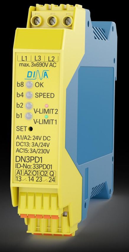
Schematic, operating element and display
L1, L2, L3 Measuring inputs
L1 L3 L2 A1 Power supply
+24V DC
A2 0V
b8 OK Q Acknowledgment input
b4 SPEED
O1, O2 Diagnostics outputs
SET b2
13-14/23-24 Enabling contacts
b1
SET Configuration button
b1, b2, b4, b8 parameter 1-15
OK Ready for operation
24 V DC SPEED Speed Status
A1 A2 O1 O2 Q 13 14 23 24
Terminal description
A1/ A2 Power supply 24V DC
L1, L2, L3 Measuring inputs are to be connected directly to the motor, without switching contacts between.
Q Acknowledgment input can be parameterized, manually or automatically
13/14, 23/24 Enabling contacts (2 NO-contacts). These switch off immediately if the parameterized speeds are under-
shot or exceeded or internal or external errors.
13/14, 23/24 are to be used in such a way that the intended safety function, e.g. emergency stop is executed.
O1, O2 Digital positive switching semiconductor outputs for the transmission of switching states to a
higher-level control for diagnostic tasks.
10 21-06-09 / 33pd02-V0743.3.3DN3PD1
Applications
5 Applications
Motor with frequency converter L1
L2
L3
The operation on electric power drive systems with adjustable speed
is possible. (Frequency converter) FU/ FC
Test ? 24V DC
A1 Q 13 23
L1 b8 SET
L2 b4 DN3PD1
V1 L3 b2
U1 W1 b1
MV1
3 U2 A2 O1 O2 14 24
U1 V2
W2 W1
Motor with star-delta circuit L1 L2 L3
24V DC
Operation on motors with star-delta connection or pole changeover
is possible. For pole-changing motors, please note that DN3PD1 U1 V 1 W 1 A1 Q 13 23
detects the frequency and not the speed! M L1 b8 SET
L2 b4 DN3PD1
The measuring inputs L1 and L3 are bridged and directly connected 3 L3 b2
to W1 on the motor. U2 b1
V2 W2
The measuring input L2 is directly connected to W2 on the motor. A2 O1 O2 14 24
Single-phase motor L
N
Operation on a single-phase motor is possible.
The measuring inputs L1 and L3 are bridged and directly connected Test ? 24V DC
A1 Q 13 23
to U1 on the motor.
The measuring input L2 is directly connected to U2 on the motor. L1 b8 SET
L2 b4
b2
DN3PD1
U1 U2
L3 b1
M A2 O1 O2 14 24
1
Servo motor
Applications with servomotors are possible to a limited extent.
The following test must be carried out before using the DN3PD1:
When the motor is running with a motor frequency greater than the parameterized maximum frequency,
terminal L2 on the module must be disconnected.
If the enabling current path closes in this case, the module is not suitable for use on this motor.
6 Mounting and removal
Mounting on 35mm DIN rail according to EN 60715
For the removal pull the lock device using a screwdriver
Required distances according to DIN EN 50274, VDE 0660-514 must be observed
No strong magnetic fields in the installation vicinity. (Magnetic fields < 30 A/m). These can interfere with the unit.
21-06-09 / 33pd02-V0743.3 11DN3PD1
Mounting and removal
Mounting Removal
(1) DIN rail
(2) lock device
(2) (3)
(1) (3) cable channel
70-75mm 70-75mm
Wiring
Conductor cross-section of 1.5 mm² must not be undercut.
Use Copper wires approved up to 60°C/75°C.
For of wire end sleeve is recommended.
Loads connected to the measuring wires are not allowed.
The placing of the measuring wires has to avoid a cross connection or short. Laying in cable channel.
The regulations according to EN 60204-1 are to be followed.
Use effective protective circuits parallel to an inductive load to avoid a shortcut of the output contacts.
The arrangements of the overcurrent protective mechanism are to consider.
Overvoltage > 32V DC destroys the unit.
Use power supply with max. 32V output voltage also with fault..
Commissioning
Switch off the unit befor you start working.
Wire the unit according to intended use
Connect the power supply 24V DC to A1 and 0V to A2.
Self-test follows. After faultless self-test the unit is in function. The LED OK is green
Example of application
Application: Output contacts connected in parallel Application: Output contacts connected in series
L1 24V
L2 L1 24V
L3 L2
L3
≤ 3A ≤ 3A
FU/ FC
14 23 FU/ FC 23
Test ?
24 A1 Q 13 23 Test ?
A1 Q 13 23
≤ 3A L1 b8 SET
∑6A L2 b4 DN3PD1 L1 b8 SET
L3 b2 L2 b4 DN3PD1
U1 V 1 W1 b1 L3 b2
M A2 O1 O2 14 24 U1 V 1 W1 b1
3 U2 V1 NC 14 24 M A2 O1 O2 14 24
3 U2 V1 NC
U1 V2
W2 W1 U1 V2
W2 W1
12 21-06-09 / 33pd02-V0743.3.3DN3PD1
Parameterization of the switching thresholds
7 Parameterization of the switching thresholds
Important notes for parameterization
Use a VDE-insulated screwdriver according to EN 60900 to press the SET button.
The switching threshold and acknowledgement must be set correctly in order to ensure safe operation; this respon-
sibility lies with the user.
To determine the switching thresholds, the number of pole pairs must be taken into account:
f [Hz]= (n [U/min] / 60) x number of pole pairs
Example: 5000 rev/min x 3 (number of pole pairs) / 60 = 250Hz
During parameterization, the output contacts are switched-off.
The parameters are not saved by voltage break or break of the parameterization for longer than 20s.
Frequency of (V-LIMIT 2 -10%) must be higher than (V-LIMIT 1).
On automatic acknowledgement must be V-LIMIT 1 ≥ 1,1Hz .
The monitoring of a minimum speed can be deselected. In this case, the lowest frequency for V-LIMIT 1 should be
selected. There is no distance to keep to V-LIMIT 2. The output contacts remain closed at standstill.
Table of frequencies
These frequencies (in Hz) can be set as switching thresholds.
Level x.1
1 2 3 4 5 6 7 8 9 10 11 12 13 14 15
1 0,15 1,26 1,96 3,05 4,8 7,4 11,5 18,0 28,00 43,6 68,0 104 159 255 396
2 0,20 1,29 2,02 3,14 4,9 7,6 11,9 18,5 28,8 44,9 70,0 106 163 263 408
3 0,30 1,33 2,08 3,24 5,04 7,9 12,2 19,1 29,70 46,3 72,1 109 167 270 418
4 0,40 1,37 2,14 3,33 5,2 8,1 12,6 19,6 30,6 47,7 74,3 112 172 278 431
5 0,50 1,41 2,20 3,43 5,35 8,3 13,0 20,2 31,5 49,1 76,5 116 178 287 443
6 0,60 1,46 2,27 3,54 5,5 8,6 13,4 20,8 32,5 50,6 78,8 119 181 295 458
7 0,70 1,50 2,34 3,64 5,7 8,8 13,8 21,5 33,4 52,1 81,1 123 187 304 471
Level x.2
8 0,80 1,55 2,41 3,75 5,8 9,1 14,2 22,1 34,4 53,7 83,6 126 191 314 485
9 0,90 1,59 2,48 3,86 6,0 9,4 14,6 22,8 35,5 55,3 86,1 130 196 323 500
10 1,00 1,64 2,55 3,98 6,2 9,7 15,1 23,5 36,5 56,9 88,7 134 214 333 514
11 1,05 1,69 2,63 4,10 6,4 10,0 15,5 24,2 37,6 58,6 91,3 138 221 342 529
12 1,10 1,74 2,71 4,22 6,6 10,3 16,0 24,9 38,8 60,4 94,1 142 227 353 544
13 1,15 1,79 2,79 4,35 6,8 10,6 16,5 25,6 39,9 62,2 97,5 147 234 363 560
14 1,18 1,85 2,88 4,48 7,0 10,9 17,0 26,4 41,1 64,1 100 150 240 374 575
15 1,22 1,90 2,96 4,61 7,2 11,2 17,5 27,2 42,0 66,0 102 155 247 385 594
21-06-09 / 33pd02-V0743.3 13DN3PD1
Parameterization of the switching thresholds
Configuration of the switching threshold and acknowledgement
The current settings can be checked by briefly pressing the SET button. The LEDs show the parameters binary coded in five
steps (Level). Two levels each determine V-LIMIT 1 and V-LIMIT 2 (see frequency table), the fifth level indicates the type of
acknowledgment.
The permanent pressing of the SET button starts the parameterization mode and the levels can be run through. Releasing
the button allows you to change this level parameter. The configuration can be adjusted by a short touch of the button. The
new setting is saved again by pressing the button permanently.
Each level can be recognized by its flashing rhythm or the LED color.
V-LIMIT 1 V-LIMIT 2 Acknowledgement
Level 1.1: column 1.2: row 2.1: column 2.2: row autom./manual
SET
b8
b4
b2
b1
Adjusting by briefly pressing the SET button Save: press SET button > 1s
Press SET button for >2s until all LED flash green.
Adjust V-LIMIT 1, Level 1.1 binary coded by short key press (column of the table 7-1)
Keep the SET button pressed: The value is saved and displayed as continuous light.
Keep the SET button pressed until the blinking rhythm of all LEDs changes.
Adjust V-LIMIT 1, Level 1.2 binary coded by short key press (row of the table 7-1).
Keep the SET button pressed: The value is saved and displayed as continuous light.
Keep the SET button pressed until the color of all LEDs changes.
Adjust V-LIMIT 2, Level 1.1 binary coded by short key press (column of the table 7-1)
Keep the SET button pressed: The value is saved and displayed as continuous light.
Keep the SET button pressed until the blinking rhythm of all LEDs changes.
Adjust V-LIMIT 2, Level 1.2 binary coded by short key press (row of the table 7-1).
Keep the SET button pressed. The value is saved and displayed as continuous light.
Keep the SET button pressed until the LED flash in pairs.
Adjust the acknowledgement*) by short key press
Keep the SET button pressed: The value is saved and displayed as continuous light.
Release the button. The configuration is completed. The unit is ready for operation, if the OK LED shows green.
*) Adjust the acknowledgement
b8 b8
b4 b4
b2 b2
b1 b1
-
manual SET automatic
The set thresholds must be validated as follows:
Checking the set parameters in the display mode (short pressing of the SET key) and verification of the correct
safety functions by checking the shutdown speeds, e.g. by comparison with the speed displayed on the frequency
converter or use of other suitable speed measuring equipment.
14 21-06-09 / 33pd02-V0743.3.3DN3PD1
Parameterization of the switching thresholds
Example for configuration
V-LIMIT 1 = 1,0 Hz V-LIMIT 2 = 297,9 Hz Acknowledgement
Level 1.1 Level 1.2 Level 2.1 Level 2.2 manual
column 1 row 10 column 14 row 6
b8 b8 b8 b8 b8
b4 b4 b4 b4 b4
b2 b2 b2 b2 b2
b1 b1 b1 b1 b1
21-06-09 / 33pd02-V0743.3 15DN3PD1
Diagnostics
8 Diagnostics
The 2-color LEDs (b1, b2, b4, b8) indicate operational readiness, switching status, internal and external errors.
The semiconductor output O1 is switched on when the frequency is within the parameterized range. See Fig. 8-1
The semiconductor output O2 indicates the operational readiness. This switches off in case of an error.
LED OK LED SPEED O1 O2 13/14, 23/24 Status
green green 24V 24V acknowledged in range
green off 0V 24V not acknowledged out of range
green flashing green 0V 24V acknowledged out of range
green off 24V 24V not acknowledged in range
flashing red off 0V 0V error see error report
Fig. 8-1
Error report
The safety relay displays error messages using LED flashing codes.
The blink code is repeated continuously with a break of 1 s.
The meaning of the individual LED blink codes can be found in the table.
Example:
3 x flash / 1 s break / 3 x flash / 1 s break ...
That means error no. 3.
Flash-code Possible cause Remedy
1 x flash incorrect power supply Check power supply
UB< 20V, > 32V UB = 20.5V-26,5V DC
2 x flash (V-LIMIT 2) < (V-LIMIT 1) (V-LIMIT 2 – 10%) > (V-LIMIT 1)!
3 x flash incorrect acknowledge signal Check the wiring at input Q for cross or
Q < 200ms oder > 10s short circuits.
For manual acknowledgment:
Check whether the start signal is within
the time range of min. 200ms to max. 10s.
4 x flash open-circuit on L1, L2, L3 Check the wiring at the measuring inputs
for
short circuit
cross-connection
wire break
5 x flash single-channel measuring Check the wiring at the measuring inputs
for
short circuit
16 21-06-09 / 33pd02-V0743.3.3DN3PD1
Diagnostics
cross-connection
wire break
6 x flash relay error Send the device to DINA Elektronik for
testing.
7 x flash internal error Send the device to DINA Elektronik for
testing.
8 x flash Measuring is different on master/slave Send the device to DINA Elektronik for
testing.
9 x flash Frequency > 800Hz check the frequency at the measuring
inputs
10 x flash Internal error Send the device to DINA Elektronik for
testing.
21-06-09 / 33pd02-V0743.3 17DN3PD1
Technical data
9 Technical data
Ambient conditions
Ambient temperature (operation) -20 to +55°C DIN IEC 60068-2-3
Ambient temperature (storage) -40 to +85°C DIN IEC 60068-2-3
Maximum altitude max. 2000m (above sea level)
Vibration resistance 3 axis Sinus 10–55Hz, 0,35mm, 10 cycles, 1 octave/min
Air and creepage distances DIN EN 50178, safe isolation
Protection class Installation in a closed cabinet, min. IP54
Input data
Operating voltage UB 24V DC -15 % / +10 %, reverse protection
Current draw at 24V DC typ. 80mA
Current draw at L1, L2, L3 0,35mA at 690V AC
Input voltage at L1, L2, L3 90 to 690V AC
Input frequency at L1, L2, L3 ≤ 600 Hz
Switching hysteresis 10%
Power consumption at A1/ A2 typ. 1,9W
Status display 4 x LED 2-color
Protection wiring Overvoltage/ inverse polarity protection
Output data
Contact type 2 enabling NO-contacts
Contact material AgSnO2
Operating voltage 24V DC / 230V AC
Minimum switching current 3 mA/ 24V DC
Maximum switching current 6A / 24V DC/ 230V AC
Short-circuit strength 1000A SCPD 6A gL/gG
Mechanical life 107 switching cycles
Switch-off time 01 Up to 30 Hz: 1 period (reciprocal value of the set frequency) + 10ms
Over 30 Hz: 3 x 1 period + 10ms
Switch-off time 02 Up to 2,5 Hz: 1 period (reciprocal value of the set frequency) + 10ms
Over 2,5 Hz: 2 x 1 period + 10ms
Output fuse 6 A gL/gG
B10d values acc. to AC15: 5A/230V AC, >2x10⁵, DC13: 4A/24V DC, >3x10⁵
5
DIN EN 61810-2-1, 01.2012 AC1: 6A/230V AC, >2x10 DC1: 6A/ 24V DC, >7x10⁵ switching cycles
Total current 13-14 and 23-24 with parallel connection: 6A with serial connection: 3A
Outputs O1, O2 ≤ 100mA( UB-1V) shot-circuit and overload protection
General data
Nominal operating mode 100 %
Protection class IP20
Mounting position vertical or horizontal
Housing material/ Type Polyamide PA not increased/ ME/ Phoenix Contact
Dimensions B x H x T/ 22,5 x 114 x 111 mm
Degree of pollution 2
Overvoltage category III
Connection data
Terminals/ Material Push-in, pluggable/ PA Screw, pluggable /PA
Number of pins 4 5 3
Rated surge voltage 4kV 2,5kV 8kV
Rated insulation voltage 320V 160V 1000V
Conductor cross-section, flexible 0,25 - 2,5mm2 0,25 - 1,5mm2 0,25 - 2,5mm2
with wire end sleeve
Conductor cross section AWG 24…12 24…16 24…12
Connection wire 60/75°C Copper
Tightening torque min/max - - 0,5Nm/0,6Nm
18 21-06-09 / 33pd02-V0743.3.3DN3PD1
Dimensions
Relay load curve
1000
ohmic load L/R = 0ms
inductive load L/R = 40ms
300
DC Spannung / DC volt age
200
L / R = 0 ms
100
50
40
30
L / R = 40 ms
20
10
0.1 0.2 0.3 0.4 0.5 1 2 3 4 5 6 10
DC Schalt st rom (A) / DC Swit ching current (A)
WARNING
Loads with high capacitive component can destroy the output contacts because the switching current is very
high.
10 Dimensions
111 22.5
114
21-06-09 / 33pd02-V0743.3 19wir sind sicherheit. DINA Elektronik GmbH Esslinger Str. 84 D72649 Wolfschlugen Phone +49 7022 95170 Fax +49 7022 9517700 info@dina.de www.dina.de
You can also read