Energy Generation in Tyres using Piezoelectric Material - IJERT
←
→
Page content transcription
If your browser does not render page correctly, please read the page content below
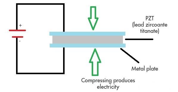
Published by : International Journal of Engineering Research & Technology (IJERT)
 http://www.ijert.org ISSN: 2278-0181
 Vol. 9 Issue 07, July-2020

 Energy Generation in Tyres using
 Piezoelectric Material
 Aditya Pandey1, Tejas Bansal2, Amey Konde3, Rushikesh Giri4, Sarvesh Gandhi5
 1,2,3,4,5
 UG. Student, School of Mechanical Engineering
 Dr. Vishwanath Karad’s MIT World Peace University
 Pune, India.

 Abstract- In the project, Energy is being harnessed from When piezoelectric material is placed under mechanical stress
the tyres with the help of Piezoelectric material. The energy the spontaneous separation of charge with certain crystal
dissipated by the wheels to the surrounding can be captured structures under the right conditions, which results in an
and transformed into electrical energy. Tyres are a good external electrical field. This phenomenon, referred to as
source of pulsating/alternating force which can be spontaneous polarization, is caused by a displacement of the
converted into alternating current. The tyres experience electron clouds relative to their individual atomic centers, i.e.,
undulations and vibrations while braking as well as a displacement of the positive ions relative to the negative ions
accelerating, vertical reaction forces while riding over within their crystal cells. Such a situation produces an electric
bumps and potholes, hence justifying the need of a dipole.
mechanism. This mechanism has vast applications and can
open the door to endless innovative ideas for energy
harvesting in Automobile sector and subsequent fields.

 Keywords— Energy Harvesting, Piezoelectric effect,
Piezoelectric material, Ceramics, Tyres, Power generation.

 I. INTRODUCTION
With the everyday developing and growing world, there is also
a growing demand for energy supplies. With the increase in
 Figure 1. Piezoelectric Effect
demand there is an increase in concern in the depletion of
resources used to generate energy the traditional way. Society
is developing new alternative non-conventional methods which
are gaining much popularity in today’s world. Many popular
and successful methods are the Solar cells, Wind energy, B. Piezoelectric material and material selection
hydroelectric energy, geothermal, biogas plants. With the ever- There are many natural and man-made piezoelectric materials
growing Automotive industry and introduction of HEV’s and currently in use. Some of the naturally occurring materials are
EV’s, a lot of energy is required to mobilize them. There is a Sucrose (table sugar), Rochelle salt (Produces a large voltage
need to cater this energy. Piezoelectric material and effect play with compression; used in early crystal microphones), Topaz,
a major role in solving this problem. The vibrations and Tourmaline, Berlinite (AlPO4; a rare phosphate mineral
undulations from the vehicular motion can be converted into structurally identical to quartz). Some of the piezoelectric
electrical energy using piezoelectric effect. Tyres of the vehicle ceramics are Barium titanate (BaTiO3). Potassium niobate
are subjected to normal and shear loads, this load can be used (KNbO3), Lithium niobate (LiNbO3), Lithium tantalate
as the source of mechanical stress for the piezoelectric material. (LiTaO3), Sodium tungstate (Na2WO4), Lead titanate (PbTiO3).
This project is based on a case study on a tyre of Tata Nexon Lead zirconate titanate or PZT is currently the most used
EV currently running on road. piezoelectric ceramics and used in many applications.

 II. THEORY
A. Piezoelectric effect
Piezoelectricity is the property of dielectric materials to
physically deform when an electric field is present, or
conversely, to produce an electrical charge when they are
mechanically deformed, this property is also known as
Piezoelectric effect. There are a variety of materials which
show this phenomenon such as natural quartz crystals, semi-
crystalline polyvinylidene polymer, polycrystalline
piezoceramic, bone and even wood.

 IJERTV9IS070547 www.ijert.org 1178
 (This work is licensed under a Creative Commons Attribution 4.0 International License.)
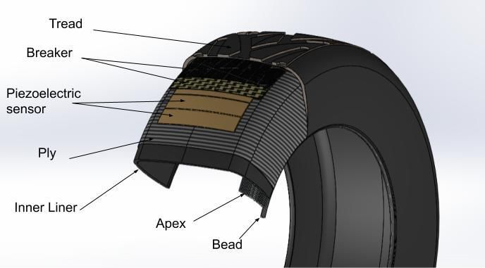
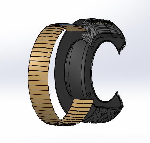
Published by : International Journal of Engineering Research & Technology (IJERT)
 http://www.ijert.org ISSN: 2278-0181
 Vol. 9 Issue 07, July-2020

Piezoelectric material properties:
dij – This piezoelectric constant is the ratio of mechanical strain
to applied electric field at constant stress (m/V). Conversely, it
is the ratio of electric displacement to mechanical stress at
constant electric field (C/N), ‘i’ indicates that the electrodes are
perpendicular to ‘i’ no. of axes and ‘j’ indicates that the
piezoelectricity induced strain, or the applied stress, is in
direction ‘j’ [1].
gij – This piezoelectric constant is the ratio of electric field to
applied mechanical stress at constant electric displacement
(Vm/N). Conversely, it is the ratio of mechanical strain to
electric displacement at constant stress (m2/C).
Curie temperature – This is the temperature above which the
crystal structure changes to a symmetrical, non-piezoelectric
form. The dielectric constant peaks and the net polarization Figure 2. Properties of packaging materials
completely disappears at the Curie temperature.
 There is a wide range of material used for making a tyre. The
C. Properties of PZT basic materials are: carbon black for wear resistance, silica as a
• Dielectric constant (@1KHz) = 1800 high-grade material that ensure short stopping distance on wet
• Piezoelectric strain coefficient, d33 = 390 × 10-12 m/V road it is one of the important materials in tread and other
• Piezoelectric Voltage coefficient, g33 = 24 × 10-3 Vm/N additives such as antioxidants which protect the tire against
• Elastic Modulus = 4.9 × 10¹⁰ N/m2 premature aging, natural rubber and synthetic rubber. The
• Compressive strength = 5.2 × 10⁸ N/mm2 secondary material which is used to vary the property of the
• Tensile Strength: (Static) = 7.5 × 10⁷ N/mm2 basic compound for the respective application are: chalk, oils,
 (Dynamic) = 2 × 10⁷ N/mm2 resin, accelerating agent, retardants, compounding promoters,
• Curie Temperature = 350oC [2]. activators and Sulphur.
Due to its desired properties such as high compressive and There are different layers in tyres and the function of each layer
tensile stress, and a high Curie temperature to withstand the heat is different:
during the vulcanization process, PZT-5A have been selected 1. Inner liner: It is the innermost layer of the tyre. It is a thin air-
as the piezoelectric material in this project. tight layer made up from a composition of rubbers. It replaces
 the tubes present the previous generation tyres.
D. Packaging of PZT 2. Ply (above the inner liner): It consists of thin textile cords
PZT-5A - is best for applications that have extreme covered with rubber compound in radial direction. It acts as a
temperatures and/or a widely varying temperature but the reinforcement material. It also determines the load rate of tyre
performance is desired to remain constant. and the cushioning factor.
Tyre faces continuous forces acting on it, PZT being brittle may 3. Bead and Apex: Bead is a combination of steel wires covered
not withstand these continuous loads. To make the PZT with rubber compounds. It keeps the tyre seated on the rim.
modules robust packaging is a must. While packaging the piezo Apex is a series of steel cord along the height of the tyre or side
wafers are sandwiched between thin, flexible circuits. wall. Apex provides driving stability and improves steering
Typically, either FR4 is used (like those in a standard printed performance.
circuit board) or Polyimide for the flex circuits, but any circuit 4. Breaker: Breaker is a layer of rubber coated steel cord placed
material can theoretically be used. at an acute angle to the axis of tyre. It maintains rigidity of tread
A layer of high-temperature polysulfone plastic is used to align in longitudinal and lateral direction. It ensures power
all the layers to the copper connections in the flex circuits. transmission during driving and ensures stable cornering. It also
Finally, a high-temperature epoxy is used to adhere all the increases the resistance to wear. There are two layers of breaker
layers together in the packaging process. This creates a robust, in tyre present at the opposite direction to each other.
hermetically sealed, electrically insulated transducer with easy 5. After the breaker there is a layer of nylon in the form of a net.
connection. Packaging also reduces the risk of lead exposure It helps to maintain the shape of the tyre when it is at high speed
[3]. and temperature.
 6. Tread: It is the layer which comes in contact with the road. It
 III. ORIENTATION OF PZT MODULES improves grip and durability of tyre and reduces rolling
A. Tyre composition resistance.
Selected tyre for the project: - Tata Nexon has a tyre size of 7. Before the vulcanization process; the tread, cap ply, and
215/60 R16 [4]. breaker are considered as one unit and the bead, apex, inner
Where 215 - is the width of the tyre linear and ply as another. During assemblage these are brought
 60 - is the aspect ratio together.
 R- signifies it is Radial
 16 - is the rim diameter
The height of the tyre will be (60 × 215)/100 = 129 mm.
 B. Orientation of Piezo-electric

 IJERTV9IS070547 www.ijert.org 1179
 (This work is licensed under a Creative Commons Attribution 4.0 International License.)
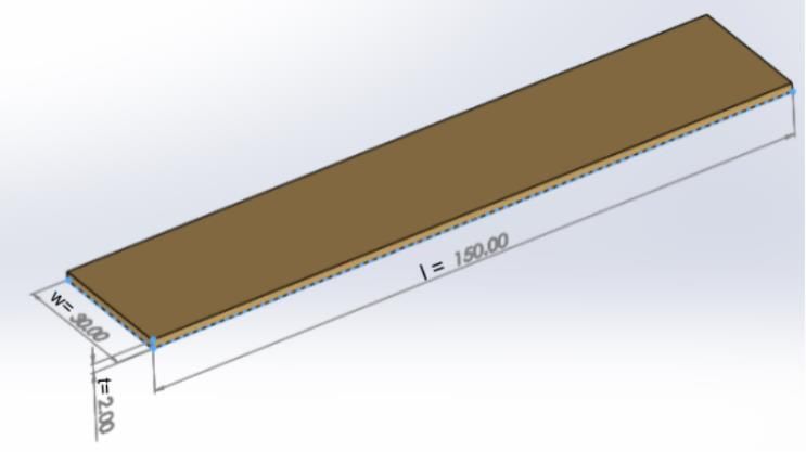
Published by : International Journal of Engineering Research & Technology (IJERT)
 http://www.ijert.org ISSN: 2278-0181
 Vol. 9 Issue 07, July-2020

• Unit 1: During the manufacturing process the first layer will IV. DIMENSIONS OF PZT MODULES
be an inner liner followed by a layer of ply with the bead and
the apex on the sides. After these layers are placed on the
machine, the layer of piezoelectric sensor would be placed on
top of the ply. Before applying the side wall to the unit, the
piezoelectric wiring is taken out for later connection. The side
wall’s layer is placed above the wiring. Using these
arrangements, the wire connection is concealed within the tyre.
• Unit 2: the bottom layer comprises of two layers of breaker,
followed by cap ply and the layer of tread.
C. Assemblage
Unit 2 is placed over unit 1 which are glued together by
applying air pressure. Then the assembly is sent for
vulcanization. Figure 5. PZT Module
Vulcanization is a process in which the hot steam is passed
through the membrane which is in contact with the inner side of A. Length (l)
the tyre. The outer side of the tyre is in contact with the mold The specifications of the Tata Nexon EV tyre are 215/60 R16,
which is also known as curing mold. In this process the tire gets therefore the width of the tyre is 215mm. Assuming the
its marking and tread pattern. Because of the temperature, all thickness of the sidewall as 20mm, and by providing some
layers inside of the tire become one. The temperature range is clearance space for the wiring and mountings (10mm on each
between 170 -200 degree C and at pressure of 22 bar for around side), 150mm of total free space was available and hence
10 min. The values depend on the size of the tyre. customized the piezoelectric sensors to the desired length of
 150 mm.

 B. Width (w)
 The width of the plates is dependent on the contact patch area
 of the tyre; therefore, the contact patch area is:
 For Tata Nexon EV the Tire Pressure is 35psi, which is 0.2413
 N/mm2
 Area = (Force on the wheel)/ (Tire Pressure)
 Area = 456.25 × 9.18/0.2413 = 18548.746 mm2
 Therefore, 18548.746mm2 / 150mm = 123.66 mm
 Therefore, a single plate of 120mm can be used or multiple
 plates of lower dimension (greater the number of plates, greater
 is the uniform weight distribution over the plate). Therefore, 4
 Figure 4. Assembly of PZT Modules plates of width 30 mm were finalized with a spacing of 1 mm
 in between them.

 C. Number of plates
 The location of the piezoelectric sensors is assumed to be 20
 mm below the outer surface (tread) of the wheel. Therefore, the
 diameter of the location is 624.4 mm. Since, the width of the
 plate is 30 mm and the clearance in between them is 1 mm, the
 total number of plates is:
 = (624.4 × ) / (30+1)
 = 63.277 ≈ 63 plates

 D. Thickness (t)
 The thickness of the piezoelectric plate is directly proportional
 to the energy generated by it, but with increase in the thickness,
 Figure 3. Exploded view of PZT Modules the physical properties of the material is emphasized resulting
 in higher brittleness. Also, a thicker plate would hamper the
 properties of the tyre which is not preferred.
 Therefore, an optimum thickness has to be selected for the most
 efficient and physically viable power generation. Since the
 thickness of plies is greater than 3mm [5], piezoelectric plates
 of 2 mm thickness have been finalized.

 IJERTV9IS070547 www.ijert.org 1180
 (This work is licensed under a Creative Commons Attribution 4.0 International License.)
Published by : International Journal of Engineering Research & Technology (IJERT)
 http://www.ijert.org ISSN: 2278-0181
 Vol. 9 Issue 07, July-2020

 V. DETAILED MATHEMATICAL CALCULATIONS
A. Division of Vehicle load F. Power
Kerb Weight of the vehicle = 1400kg To calculate the Power generated by a single plate:
Weight of passengers = (5 × 85) = 425kg. Power = Voltage × Charge
Since the vehicle is a TATA Nexon EV which is a 5-seater and Power = 15.914 × 0.585
assuming that the weight of each passenger is 85kg. Power = 9.30969µW
Gross weight = Kerb weight + Weight of passenger
 = (1400 + 425) kg = 1825 kg G. There are a total 63 piezoelectric plates in a single tire.
Taking the weight distribution of the vehicle as (50-50), the Therefore, the power generated by a single rotation of a tire is:
load on the front and rear wheels are: Total Power for 63 plates = 63 × 9.30969 = 586.51µW per
Front wheels = 50% of 1825kg = 912.5kg rotation.
Rear wheels = 50% of 1825kg = 912.5kg
Since the load on the front and rear wheels is same, load on each H. Assuming that the vehicle is being driven at a velocity of
wheel = 912.5 / 2 = 456.25kg. 80km/hr i.e. 22.22m/sec.
 For 22.22m/sec,
B. Contact Patch Area RPM= velocity/circumference of the tire
It is the area which will be in contact with the surface when the RPM = 22.22/π×0.6644 = 10.64 rotation/sec
vehicle is at rest or in motion.
To calculate Contact Patch Area, the pressure of the tyre is I. Power output on wheel:
needed. Power output per second per wheel = 10.64×589.51
For Tata Nexon EV, the Tire Pressure is 35psi (0.2413 N/mm2) Power output per second per wheel = 6240.4664µW
Contact Patch Area = (Force on the wheel) / (Tire Pressure)
Contact Patch Area = 456.25 × 9.18 / 0.2413 J. The Power output from 4 wheels in 1 second.
= 18548.746 mm2. = 6240.4664 х 4
C. Voltage = 24961.8656µW
The voltage generated is directly proportional to the induced
mechanical stress(ᓂ). Therefore, Open Circuit Voltage (OCV) K. Power output in 1 hour
of the ceramic plates is calculated. =24961.8656 × 3600
Induced mechanical stress(ᓂ) is: = 89862716.16µW
ᓂ = Force on each ceramic plate/Area of the ceramic plate
 Power output from the vehicle is 89.86Wh
ᓂ = 456.25 × 9.81 / 3 × (0.015 × 0.03)
ᓂ = 331540.7407 N/m2
 VI. ELECTRICAL
Therefore, the generated open circuit voltage is: The PZT units are connected in parallel as current obtained is
O.C.V = g33 × ᓂ × t more than that of series connection. The output from the PZT
O.C.V = 24×10-3 × 331540.7407 × 0.002 unit is AC, which cannot be used to charge the battery.
O.C.V = 15.914 V Therefore, a Full Wave Rectifier is used to convert AC to DC.
 The Rectifier consists of 4 or more diodes arranged in the bridge
D. Charge density circuit configuration. The bridge rectifier consists of 4 diodes
Charge Density is defined as the amount of electric charge per D1, D2, D3, and D4 in which the AC input of PZT is supplied
unit length. across two terminals while the DC output is stored in the battery
Charge Density = d33 × ᓂ through the remaining two terminals. The AC consists of two
Charge Density = 390 × 10-12 × 331540.740 cycles:
Charge Density = 1.3 × 10⁻⁴ N/Vm 1. Positive half cycle: During this cycle diodes D1and D2 are in
 forward bias while D3 and D4 are in reverse bias. The current
E. Charge on Each Plate flows through diode D1, then through the load, and finally
Since the voltage generated and the charge density of the plate completing the circuit by passing through D2.
is known, the charge on each plate is: 2. Negative half cycle: During this cycle diodes D3and D4 are
Charge on each plate = Charge Density × Area of a single plate in forward bias while D1 and D2 are in reverse bias. The current
Charge on each plate = 1.3 × 10-4 × (0.15 × 0.03) flows through diode D3, then through the load, and finally
Charge on each plate = 5.85 × 10⁻⁷ Nm/V = 5.85 × 10⁻⁷ µW completing the circuit by passing through D4.
 During both cycles, the current passes through the load. Hence
 converting both half cycles of input AC to pulsating DC.
 The DC output which we get consists of some ripples. To
 reduce these ripples, a filter is used. A capacitor is used as a
 filter which is connected across the battery. For getting constant

 Figure 6. Block diagram

 IJERTV9IS070547 www.ijert.org 1181
 (This work is licensed under a Creative Commons Attribution 4.0 International License.)
Published by : International Journal of Engineering Research & Technology (IJERT)
 http://www.ijert.org ISSN: 2278-0181
 Vol. 9 Issue 07, July-2020

voltage, a voltage regulator is used, which is connected across 89.86Wh which can provide an extension of 1 km in Tata
the output of the bridge rectifier and load as shown in the figure. Nexon EV for every 80 kms driven per hour.
 VIII. CONCLUSION
 The study proves that the mechanism is not efficient enough to
 generate energy required to fully energize any vehicle, but it
 can be used to increase the range of the same. This mechanism
 has vast applications which can revolutionize the future of
 electric vehicles. The study also justifies the need of
 advancements in the material selection for the piezoelectric
 sensors.

 IX. APPLICATIONS
 Piezoelectric sensors have a wide range of applications out of
 which, harvesting of energy is the most important one. The
 energy harnessed from the alternating/pulsating force exerted
 on the wheels can be used to energize various objects like:
 1. A 48 V Lithium ion battery which can act as a power source
 for electric two-wheelers
 2. This mechanism can be installed in transportation vehicles to
 harness energy which can be further sold to the electric vehicle
 power stations.
 X. FUTURE SCOPE
 1. The mechanism can be installed and various other
 components of an automobile, for ex: suspension system and
 harness energy. Piezoelectric plate can be fitted in between the
 leaves of a leaf suspension and also in between the gaps of a
 damper spring to generate electricity.
 2. Advanced substitutes for the conventional piezoelectric
 material have to be invented which are more flexible, cheaper
 and highly efficient.
 Figure 7. Circuit Diagram
 XI. References
B. Selection of diode [1] Electro-ceramics products and material specification Harris
For the selection of diode, we considered the following terms: Technology to connect, inform and protect www.Harris.com
 [2] https://piezo.com/pages/piezo-material
1. PIV (Peak Inverse Voltage): It is the maximum voltage that [3] https://support.piezo.com/article/62-material-properties
the diode can block when it is in reverse bias, if it exceeds that [4] https://cars.tatamotors.com/suv/nexon/specifications
value it gets damaged. The value of PIV must be higher than [5] https://www.olympus-ims.com/en/applications/measuring- thickness-
the input voltage needed for the filter. rubber-
 tires/#:~:text=These%20gages%20are%20used%20mostly,0.010%20i
The maximum value of Voltage for a single tyre is 15.914V ≈ n.)%20or%20better.
16V. Therefore, we need a diode having PIV greater than 16V. [6] Ayan Bhattacharya, “Piezoelectric Energy Harvesting in Automobile
2. If (Average Forward Current): It is current flowing through Wheel”, IJTRE, Vol.5, Issue 11, July 2018.
the diode when it is forward bias. [7] Muhammad Kamran, Dr. Raziq Yaqub, Dr. Azam ul Asar,
 “Autonomously Battery Charging Tyre for EVs using Piezoelectric
3. Ifm (Repetitive Surge Current): It is the maximum current phenomenon”, Int’l Conf., Modeling, Sim. and Vis. Method, MSV’17.
which the diode can carry.
Ifm for a single tyre is 0.585μA × 63 = 36.855μA.
4. Vf (Forward Voltage Drop): It is the voltage across the diode
when it is in forward bias. It should be as low as possible.
5. Operating Temperature: It is the temperature range in which
a diode can work without getting damaged.

 VII. RESULT
The power output in 1 hour when the vehicle is driven at 80
kmph is 89.8627 Wh. The mechanism is capable of generating

 IJERTV9IS070547 www.ijert.org 1182
 (This work is licensed under a Creative Commons Attribution 4.0 International License.)
You can also read