Formula 1 2018 Technical review - The Chelsea Magazine Company
←
→
Page content transcription
If your browser does not render page correctly, please read the page content below
Leading-Edge Motorsport Technology Since 1990

Formula 1
Technical review

2018
30 & 31 October 2019 | NEC, Birmingham

The UK’s largest annual gathering of
OEMs and engineering supply chain
professionals

        91%
     of exhibitors met their
                                             88%
                                         of exhibitors have either
                                                                                       98%
                                                                                   of exhibitors were satisfied
   objectives of networking             booked or will be booking                   with their experience at
  with new and existing clients               again for 2019                      Advanced Engineering 2018

                                                   Secure your stand today

       “We have done this for the 5th                                “I found the event a great
       year in a row and it is a very                                networking opportunity to meet
       good event for us to meet new                                 industrial professionals from
       clients.”                                                     different backgrounds with
       Thomas Evans, Business                                        different products.”
       Development Manager,
                                                                     Kat Clarke, Wing Manufacturing
       EBS Automation Ltd
                                                                     Engineer, Airbus

Secure your stand now
www.advancedengineeringuk.com
CONTENTS

                                             M
                                                            ercedes dominated the 2018                    This year also saw the introduction of the
4      Unintended consequences                              Formula 1 season, wrapping up             Halo head protection system, which has changed
       How an attempt to curb aero                          the constructors’ title as well as the    the ethos of the world’s premier single seat
       development has had a dramatic                       drivers’ title for Lewis Hamilton. But,   series. Open cockpits have always been at the
       effect on CFD in Formula 1 in 2018    this was not a walkover by any stretch. The team         heart of open wheel racing, but the Halo has
14     Pressure sensors                      believed, as did many observers, that Ferrari had        fundamentally changed that.
       Simon McBeath and the latest          the better car in the middle of the season, and              The new mounting hardware, and meeting
       advances in scanning technology       was unable to convert that advantage into a title.       some incredible crash testing targets, means
20     Halo protection                           We are now coming to the end of a rule-set           weight. This has led to a technical challenge for
       Gemma Hatton on what makes the        and finally we have the 2019 regulations to              the Formula 1 teams, one that no doubt will be
       Halo such a capable safety device     hand. There have been steps taken to improve             refined in the 2019 racecars.
28     Safety drive                          overtaking, to increase the life of engines, and             Further safety features will come next year, in
       New helmet design for 2019 revealed   to reduce the array of tyre choices that are             the form of new helmet design. Head protection
       as the FIA steps up safety campaign   available for each race, while retaining the spirit      has been a focal point of recent FIA investigations
34     Big wheels keep turning               of competition. But this is not the end of the           and only now are we starting to see the results
       Why Formula 1 has finally taken the   story. As we discovered this year, the regulations       that will benefit drivers in the near future. On a
       plunge and gone for 18-inch wheels    surrounding the computing restrictions need              lighter note, the cars will be fitted with 18-inch
42     Cool runnings                         work, and since we ran the article (see page 4) the      wheels in future, which will have an extraordinary
       Sam Collins uses Caterham’s 2014      FIA has announced a change, but not one that we          impact on suspension and chassis design.
       data to explain F1 cooling tech       expected. While the computing power limitations              One shadow on the horizon is the news
                                             meant a waste of money, the FIA has opened up            that Porsche will not be coming into Formula 1.
Produced by Racecar Engineering team
                                             those restrictions to ensure more data comes             This lack of new blood is worrying; unless new
                                             its way, and therefore it will be in a position to       manufacturers join, Formula 1 must survive
                                             do a more competent job on the next set of               with the power unit suppliers currently in play
                                             regulations, due out in 2021.                            (Renault, Ferrari and Mercedes). This puts them in
                                                 It was a smart move, but the costs are within        a very strong negotiating position, as the loss of
                                             the reach of only the wealthiest of teams. In this       one of them would have far-reaching impact on
                                             supplement, we also look at pressure sensors, and        the remaining manufacturers.
                                             how they can impact the rate of development and          ANDREW COTTON
                                             the lessons learned in testing.                          Editor

                                                                                            FORMULA 1 · WINTER 2018 www.racecar-engineering.com 3
TECHNOLOGY – AERODYNAMICS

Know your
limits
This year Formula 1’s CFD
restriction regime has been
shaken up big time as the
FIA looks to cut the costs of
aerodynamic development.
But has it worked, and how
has it changed both the
tools and the process?
Racecar investigates
By GEMMA HATTON

I
     n January 2018, the FIA introduced the latest evolution
     of aerodynamic testing restrictions for Formula 1, and
     with them came the biggest change in CFD restrictions
     since they were first introduced back in 2009. Racecar
went behind the scenes with HPC specialist, Boston Ltd, to
discover the impact of these changes and how Formula 1
teams have not only benchmarked new solutions, but also
upgraded their CFD supercomputers.
     But to put these latest changes into context we need
to understand the history of the restrictions, both for CFD
and the wind tunnel. In 2008, aerodynamic testing was at
its peak. BMW Sauber, Honda, Williams and Toyota had all
invested huge sums of money in new state of the art full
size wind tunnels, each costing tens of millions of pounds.
All the top teams were operating in two wind tunnels
simultaneously, while Toyota was not only using two wind
tunnels 24/7, but each of these was full size.
     However, the vast majority of this wind tunnel testing
utilised scale models, and over the years the scale of these
models increased from 40 per cent to 50 per cent and then
60 per cent. Operating two wind tunnels full time allowed
these teams to complete around 500 wind tunnel simulations
                                                                UNIFI LTD

per week, with each simulation incorporating approximately
20 different car attitudes. Full size wind tunnel testing was
commonplace, with teams either using their own facility or a                Boston worked together with UniFi and CE to benchmark the performance of new CFD technologies in
customer facility such as Windshear in the USA.                             accordance with the 2018 regulations to see if F1 teams would be forced to upgrade their CFD capability

4 www.racecar-engineering.com FORMULA 1 · WINTER 2018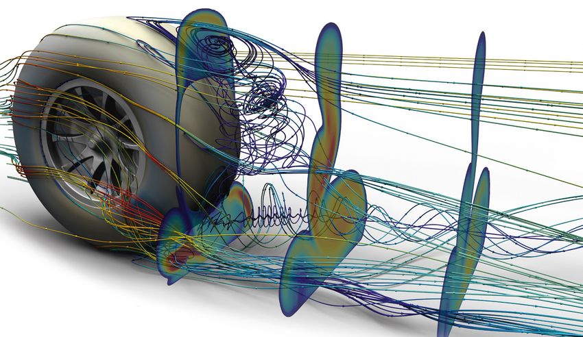
It quickly became clear that something had to be done to curb the
growth of aerodynamic testing in F1, and its associated costs

                                                  NOVEMBER 2018 www.racecar-engineering.com 5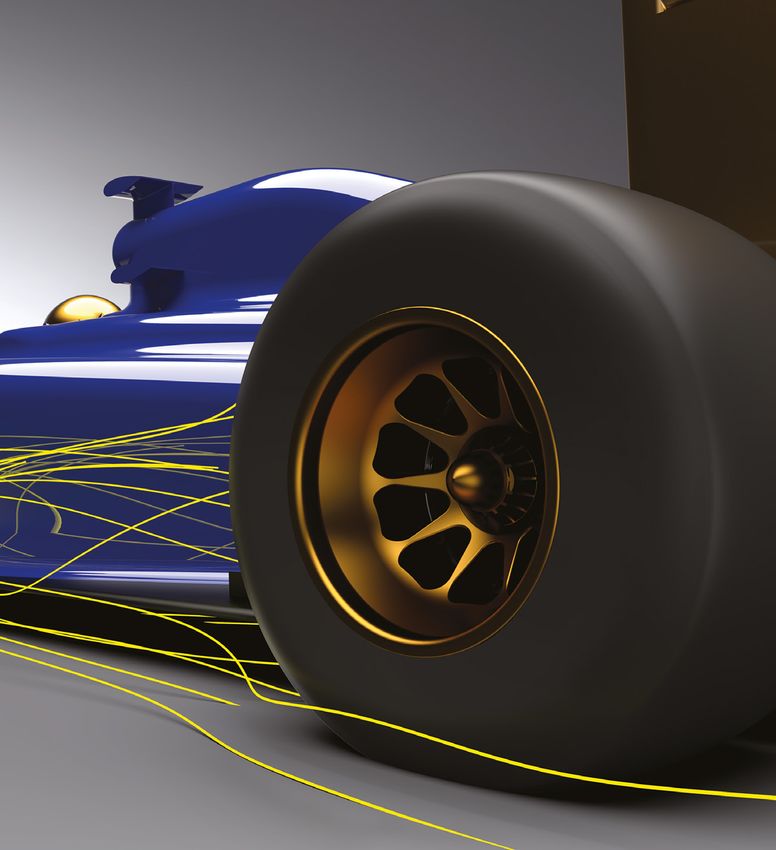
TECHNOLOGY – AERODYNAMICS

                  In 2008 teams were already using                           Between 2009 and 2017 the regulations evolved         wind tunnel. For example, let’s assume that CFD
              CFD routinely as part of the aerodynamic                       and generally served to reduce the aerodynamic        capacity allows a maximum of 12.5 TeraFLOPs.
              development process, and as the software                       resources available to the Formula 1 teams,           Using the equation with the 2013 limits results
              and correlation improved while hardware                        particularly in the wind tunnel. This was done        in 41.3 hours of wind on time, as shown by the
              costs reduced, teams began to use it more,                     through introducing a ‘limit line’ which is           green square. In 2015, however, 12.5 TeraFLOPs
              integrating it further into the design cycle.                  defined by the following equation.                    would only give you 12.5 hours in the wind
                  At that time, BMW Sauber was leading                                                                             tunnel (blue square) – that’s 70 per cent less
              the way in CFD hardware with the Albert 3                                                                            than 2013. The exact balance between CFD and
              supercomputer and over 4000 Intel cores, but                                                                         wind tunnel resources varies from team to team,
              other leading teams were not far behind. It                    Where:                                                and sometimes from year to year, depending
              quickly became clear that something had to be                  WT          = Wind on time                            on the strategic approach and technology
              done to curb the growth of aerodynamic testing                 WT_limit    = 25 hours                                advances adopted by each team.
              in Formula 1, and its associated costs.                        CFD         = TeraFLOPs usage                             Of course, every restriction that is
                  The first step came into force in January                  CFD_limit   = 25 TeraFLOPs                            introduced simply triggers the teams to
              2009 as part of the FOTA Resource Restriction                                                                        exploit the loopholes and optimise their
              Agreement (RRA). This controlled the                           Therefore, the amount of time a team chose to         designs and working practices to maximise
              aerodynamic resources the Formula 1 teams                      run its CFD directly dictated how much time it        their performance from the regulations. For
              could deploy via restrictions on the wind tunnel               could utilise the wind tunnel. Equally, if a team     the TFLOPS CFD restrictions, this became
              ‘wind on time’ (WON) and the CFD compute                       could complete its maximum allocation of wind         an arms race as teams pushed to develop
              capacity, measured in TeraFLOPS (TFLOPS).                      tunnel runs using less wind on time then it           their supercomputers to run the most CFD
                  Wind on time was simply a measure of                       would have more capacity for CFD simulations.         simulations per given TFLOP allowance. This led
              the amount of time the fan was turned on in                                                                          teams to operate CFD hardware in ways which
              the wind tunnel with the wind speed in the                     Working area                                          were quite different from the wider industry,
              test section above 15m/s. For CFD, TFLOPS                      Looking at the WT_limit and CFD_limit data            with a clear focus on regulatory efficiency
              was effectively the number of floating point                   from the last few years, Figure 1 can be created.     rather than financial efficiency. For example,
              operations completed within the designated                     Essentially, by plotting the maximum of each of       the TFLOPS calculation naturally includes a chip
              eight week Aerodynamic Testing Period (ATP)                    these limits, you can establish the ‘working area’    clock speed term which is reported either as the
              and was defined by the following equation:                     that the teams could operate in. For example,         maximum turbo clock frequency stated on the
                                                                             in 2013, when the maximum WT_limit was 60             CPU specification (if the turbo mode is used),
                                                                             hours and the maximum CFD_limit was 40                or the base clock frequency if the turbo mode
                                                                             TeraFLOPs, the team could operate anywhere            is not used. Teams quickly established that the
              Where:                                                         within the green shaded area. In 2014, the            turbo mode was not an efficient way to run
              TotFLOPs = Total number of TeraFLOPs used per second           limits were 30 hours WT and 30 CFD TeraFLOPs,         CFD simulations, in terms of the number of CFD
              MFPPC = Peak double precision floating point operations        illustrated by the red shaded area, whilst            simulations completed per TFLOP. This was also
                         per cycle per core of the processing unit           2015 was limited to 25 hours WT and 25 CFD            true for many higher clock speed chips.
              CCF      = Peak processing unit clock frequency in GigaHertz   TeraFLOPs, represented by the blue shaded area,           Effectively, running supercomputers with
              NCU = Number of processing unit cores used for the run         which remained the same until 2018.                   slow clock speed was giving teams more
              NSS      = Number of solver wall clock seconds                      Since 2013, you can see that overall testing     efficiency under the regulations but with the
                         elapsed during the run                              has dramatically reduced, but particularly for the    obvious penalty in terms of CFD simulation

Figure 1: The FIA has restricted aerodynamic testing over recent years for both CFD and the wind tunnel, but particularly the latter. This graph shows the ‘working area’ that the
teams have been able to operate in. Assuming a maximum CFD capacity of 12.5 TeraFLOPS you can see that wind on time has dropped by 70 per cent between 2013 and 2015

6 www.racecar-engineering.com FORMULA 1 · WINTER 2018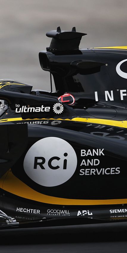
TECHNOLOGY – AERODYNAMICS

           turnaround time. Therefore, teams then had to       regulation, but it was very inefficient financially,    the FIA agreed to consider the rival Intel chips
           balance the speed with which they receive their     with as much as half of the purchased HPC               (Sandybridge and Ivybridge) as four dp flops/
           CFD results against the total number of CFD         compute cores being left idle.                          cycle for the purposes of the regulations rather
           simulations they were able to complete within           The biggest issue came when one of                  than their rated eight dp flops/cycle.
           the regulatory framework. This is quite different   the teams developed the Fangio chip in                      By 2012 AMD had been persuaded by many
           to the wider CFD industry, where the turbo          collaboration with AMD, a chip specifically             teams to produce a second limited run of Fangio
           mode was ‘free’ performance and quicker             designed to optimise the balance between CFD            chips, allowing more of the grid to upgrade
           clock speeds were performance gains if your         case turnaround time and throughput which               their supercomputers to this specification,
           main criteria was financial efficiency, and so      gave that team a huge initial advantage.                with most of the remaining teams running an
           the divide between the two environments was             This exploited the fact that the modern             Intel Ivybridge system. With the FIA unwilling
           underway from 2009 onwards.                         HPC chips were then rated at eight double               to extend the flops/cycle exemption to more
                                                               precision flops/cycle but commercial CFD                modern Intel chips, such as the V3 Haswell
           Cores and effect                                    codes were only capable of delivering                   CPUs which were rated at 16 dp flops/cycle, and
           Core under-population also became                   approximately one dp flop/cycle. The Fangio             AMD not producing any more Fangio chips, the
           commonplace in Formula 1 as it delivered            chip was designed to operate at two dp flops/           teams were now locked into these older systems
           further regulatory efficiency gains for the         cycle giving a big efficiency improvement in            purely by virtue of the regulations. Newer chips
           teams. It was efficient for the FIA TFLOPS          MFPPC. Following lobbying from various teams,           were simply not viable because of their high

                                                                                                          Fully correlated and complex CFD models, such as this by
                                                                                                          Simscale, are becoming an ever-increasing asset to F1 teams,
                                                                                                          with some full car models now exceeding one billion cells

Every restriction simply triggers teams to exploit the loopholes, and
optimise designs and working practices to maximise performance
8 www.racecar-engineering.com FORMULA 1 · WINTER 2018
TECHNOLOGY – AERODYNAMICS
BOSTON LTD

                                                                                                              A typical HPC cluster from Boston. With each new generation of
                                                                                                              compute chip delivering up to 20 per cent efficiency improvement
                                                                                                              the increased capacity of modern CFD clusters means that teams
                                                                                                              can now have an extra 200 runs, as opposed to 20 back in 2009

             flops/cycle rating. These older systems were              WON was retained and a parallel regulation was       node system based on the Intel Skylake 8176
             coming to the end of their life and were no               introduced with the aim of allowing teams to         Platinum 28 core chip. The group also had
             longer supported by Intel or AMD.                         continue using their old systems if they wished,     access to a smaller four node Intel Ivybridge
                 Clearly the FIA had to do something, and the          without too large a performance penalty – at         HPC which was used to provide a baseline of the
             target was to introduce a new regulation which            least that was the intention.                        performance gains that teams could achieve by
             aligned the Formula 1 aero departments more                   Boston Ltd has been specialising in high         upgrading from their older systems to the new
             closely with the wider CFD industry as well as            performance computing (HPC) in a wide range          hardware. This allowed Boston to benchmark its
             allowing teams to upgrade to more modern,                 of sectors for over 25 years. In 2017 it formed      own internal CFD model across a range of CFD
             supported technology. This resulted in the 2018           a new partnership with Tim Milne of UniFi            codes with a wide variety of hardware set-ups.
             CFD restrictions and a move from TFLOPS to                Engineering Services Ltd (UniFi) and Dr Lee          The systems were all set up with the very latest
             Mega Allocation Unit hours (MAUh) as defined              Axon of Computational Engineering Ltd (CE).          in networking fabric, up to date operating
             by the following equation:                                Milne and Axon have extensive Formula 1              systems and storage solutions, ensuring that
                                                                       experience, most recently at Manor F1 where          the results obtained would be aligned to the
                                                                       they were head of aerodynamics and head of           expectations of the F1 teams.
                                                                       CFD correlation respectively.
                                                                           This group combined Boston’s extensive           Hot chips
                                                                       HPC technical knowledge with UniFi’s and             Following the benchmarking of the older
             Where:                                                    CE’s F1 aerodynamics and CFD experience to           Ivybridge system, a number of options within
             AUh = Allocation unit hour                                provide the F1 teams with a comprehensive            the AMD EPYC range as well as the Skylake
             NCU = Number of processing unit cores                     benchmarking of the new AMD EPYC and Intel           8176 chip were evaluated as single node tests
             NSS = Number of solver wall clock seconds                 Skylake Platforms. They were able to use all the     to gain an initial assessment of the various
                   elapsed during the run                              main F1 CFD codes with models aligned to F1          different chips available in each family, as
             CCF = Peak processing unit clock frequency in GigaHertz   methodologies and HPC hardware set-ups to            well as some insight into the time/iteration
                                                                       extract the maximum possible performance             performance benefits of different options such
             Effectively this a very similar measure to TFLOPS         from the new regulatory environment.                 as the turbo mode. This also ensured that a clear
             but without the reliance on flops per cycle,                                                                   understanding of the raw performance of the
             hence removing the barrier to upgrading to                Node to joy                                          compute chip was gained and that the results
             newer, better supported, technology. The FIA              The project began in August 2017, by which           were not clouded by any networking issues
             commissioned an independent study to be                   time Boston Ltd was one of the first companies       which could be useful later in the process when
             carried out in order to set the regulation limit          worldwide to have invested in its own eight          trying to understand the results on the larger
             with the intention of giving parity between the           node dual socket AMD EPYC system based on            scale multi-node systems. The performance
             old regulations and the new ones. The link to             the EPYC7601 32 core chips and a similar eight       gains over the older Ivybridge system were

 The new method that was introduced at the start of this year is a very
 similar measure to TFLOPS but without the reliance on flops per cycle
 10 www.racecar-engineering.com FORMULA 1 · WINTER 2018
INTRODUCING...
THE BOSTON INTEL® SELECT SOLUTION
BUILD YOUR SUPERCOMPUTING INFRASTRUCTURE ON
BOSTON'S EXTENSIVE INDUSTRY AND DESIGN EXPERTISE FOR HIGH
PERFORMANCE COMPUTING APPLICATIONS.
BOSTON’S CFD SERVICES
THE DIFFERENCE BETWEEN
WINNING AND LOSING
Our team of motorsport experts are on hand to support with code profiling and
optimisation, can aid in tuning meshing and solver performance, and more...
VISIT: WWW.BOSTON.CO.UK/AUTOMOTIVE/CFD.ASPX
WEB: WWW.BOSTON.CO.UK
EMAIL: SALES@BOSTON.CO.UK
PHONE: +44 (0) 1727 876 100SIEMENS
TECHNOLOGY – AERODYNAMICS
Despite the efforts of the FIA to restrict the costs of CFD work, Formula 1 teams can now complete up to 1500 simulations each week on a typical model of around 200 million cells
very quickly evident and it soon became
clear that the teams would all be forced to
For example, the CFD case will be repeated
on the same HPC system but testing the It soon became clear that
upgrade their HPC systems in order to remain
competitive, which is the nature of Formula 1.
simulation on 48, 96 and 192 cores. It was
accepted that the case being run on 96 cores the teams would all be
forced to upgrade their
But this upgrade was extremely expensive. This will take slightly longer than half the time of
is not what the FIA had been aiming for, but the case on 48 cores and slightly less than
HPC systems in order to
reflects how quickly the HPC industry moves half the case being run on 192 cores – so
forward with the Formula 1 environment forced there is an element of inefficiency by running
to follow suit to remain competitive. on an increasing number of cores. However,
Once testing migrated onto the full, multi- it is in the teams’ interest to complete their remain competitive
node systems the full optimisation process CFD simulations quickly in order to allow
could begin. This involved running the same their iterative aerodynamic development
model over a wide range of different set-ups, programmes to continue as quickly as possible delivered performance gains which would
including options for memory bandwidth – so it’s a trade off and one which was vitally enable the F1 teams to run approximately twice
per core used and process bindings. The key important for the Boston group to understand. as many CFD simulations per week in 2018 than
at this stage was for the group to develop an they had been able to in 2017 (for the same
understanding of the efficiency vs performance Core values wind tunnel operation). Furthermore, the teams
of each compute system – ideally each compute The next step was to understand the impact of would complete each of these simulations in
chip in each family from Intel and AMD. leaving some of the compute cores dormant, approximately half the time that was required
In reality UniFi and CE were able to use their as previously mentioned. This is an approach under the 2017 regulations.
experience in the industry to limit the testing quite alien to most of the CFD industry (why
to the most likely candidates for Formula 1 would you buy compute cores and then not Formula 1 specific
operations and Boston used its extensive links use them?) but something that was already well Much of this optimisation is not relevant to
in the HPC industry to gain access to relevant known to deliver regulatory efficiency in the F1 the wider CFD industry, but is now considered
systems for benchmark testing. Once a small environment, if you could afford it. basic within the Formula 1 teams. The next step
range of AMD and Intel compute chips had Tests were completed leaving a range was for the Boston group to really exploit the
been selected, the focus was on understanding of the cores dormant in order to give less expertise available from the UniFi/CE group.
how they performed against the Formula 1 operational cores per memory channel, and The details of this remain confidential, but it
regulations. This required repeating the CFD thus increasingly improving the memory enabled the group to develop solutions which
simulation of their Formula 1 car on a range of bandwidth available to the CFD simulation. delivered even more performance for the F1
different HPC sizes and set-ups. The conclusion of this benchmarking study teams, and a further 20 per cent reduction
Much of this optimisation is not relevant to the wider CFD industry,
but it is now considered basic within the Formula 1 teams
12 www.racecar-engineering.com FORMULA 1 · WINTER 2018The FIA focus
remains on
reducing wind
tunnel reliance and
delivering greater
CFD capacity in
exchange, and the
current regulations
deliver that
The benchmarking study concluded that teams would gain a huge performance advantage if they purchased a new multi-
million pound system because they would have twice the CFD capacity of 2017 – this was not the aim of the regulations
in solve times was extracted from the same the huge performance advantage available by replacing their CFD clusters. In 2018, with the
CFD set-up, which also increased the CFD purchasing a new multi-million pound system, massive increase in capacity, the same 10 to
throughput by the same 20 per cent. which was not the aim of the new regulations. 20 per cent improvement available from each
Finally, as the benchmarking study neared Furthermore, the impact of the increase evolution of compute chip technology is 100
its conclusion Boston worked with AMD to in CFD capacity available to the teams under to 200 runs – that is the same as the total
further optimise for the requirements of F1 these new regulations only serves to increase capacity of the systems in 2009.
by increasing the memory bandwidth whilst the financial pressure on the teams and in Is this a bad thing? Arguably not. HPC
retaining a relatively low base clock speed. particular the pressure to increase headcount systems are much cheaper now than they
‘AMD EPYC delivers exceptional levels within the aerodynamics departments as the were back in 2009. The FIA focus remains on
of performance in a number of workloads, CFD capacity available increases. Not only reducing wind tunnel reliance and delivering
including high performance computing CFD have they effectively been required to invest greater CFD capacity in exchange, and the
applications,’ explains Roger Benson, the senior in new HPC architecture in order to remain current regulations deliver that.
director of the Datacenter Group, EMEA, AMD. competitive, but the incentive to adopt future However, does it help to level the playing
‘We are excited to be working with Boston on improvements in chip technology has now only field between the high budget teams and
their automotive engineering focused platforms increased. How so? The benchmarking work the low budget teams? Does it help to
and improving the efficiency of aerodynamic completed by Boston suggests that teams are encourage new teams into the sport? And
testing for their customers.’ now able to complete between 1000 and 1500 does it make the working practices within the
CFD simulations per week based on a typical Formula 1 aero departments more aligned
The results CFD model of around 200 million cells. Teams to the wider CFD industry?
The stated targets of the FIA for this change may elect to ‘trade’ some of this capacity for With AMD releasing its second generation
in regulations was to enable the F1 teams larger models (some teams run CFD models of EPYC chip in 2019, the reaction of the
to upgrade from their Fangio and Ivybridge approaching one billion cells) or better quality teams will be interesting. Will they all upgrade
systems to the latest technology available, but models (transient simulations rather than steady immediately? Or will the well-funded teams
without a clear performance pressure to do state). But the key point is that the F1 HPC take the opportunity to get a performance
so, and with the aim of better aligning the F1 regulations have now given the teams twice as advantage from the new technology that
industry with the wider CFD industry. much capacity to play with than in 2017. the smaller teams cannot afford?
Firstly, it is clear that all the F1 teams have
upgraded to a new system, with most teams Step change Boston, UniFi and CE continue to develop
having done so ahead of the regulatory change Typically each generation of compute chip their partnership with a focus on the F1,
date of 1 January 2018. So, the first aim has that is released by AMD/Intel delivers around motorsport and automotive industries across
been achieved – the Fangio and Ivybridge 10 to 20 per cent improvement in efficiency. all CFD codes and working practices. For
systems that the teams were operating are now Back in 2009 this would give the teams an extra more informaition visit the websites at: www.
obsolete. However, the benchmarking work 10 to 20 CFD runs per week, and therefore boston.co.uk; www.unifimotorsport.com;
completed by Boston clearly demonstrates would not easily justify the large cost in www.computationalengineering.co.uk
When AMD releases its second generation of EYPC chip in 2019 the
reaction of the Formula 1 teams is going to be very interesting
FORMULA 1 · WINTER 2018 www.racecar-engineering.com 13TECHNOLOGY – PRESSURE SENSORS
Pressure relief
Thanks to a tiny new device, measuring aerodynamic pressures on
and around cars may have just become a whole lot easier, and in
some areas actually possible for the first time. Racecar investigates
By SIMON McBEATH
P
hotographs of pre-season themselves, via tiny pressure port tunnel as well, to accurately monitor calibration of pressure sensors
and pre-race testing often tappings over and under the major and control flow conditions. for many years, and have worked
show top race teams, downforce-generating surfaces. But how are these measurements closely with a concern that might
especially in F1, measuring Using these techniques enables made? And what are the practicalities? accurately be described as the
aerodynamic pressures around their aerodynamicists to gather pressure We visited Evolution Measurement sector founder, Scanivalve (see
cars. The most obvious manifestation data around and on the car’s surfaces Ltd (see sidebar), based in Andover in sidebar) since 2001. With an intimate
of this is the pressure sensor array, like that can be used to correlate with southern England, to learn more about knowledge of the available products
a two-dimensional rake with pressure CFD and wind tunnel data, as well as the challenges involved, and to see an and, importantly, a firm grasp of
sensors arranged over the area of the to calculate the real forces acting on ultra-compact new pressure sensor the customers’ needs, Evolution
rake, positioned on the raceccar in key individual components. the company has come up with, that Measurement has come up with the
areas where what might be described Pressure measurement is an will open up exciting new possibilities. EvoScann P Series pressure scanner
as partial plane pressure plots can be everyday critical part of wind tunnel Although Evolution Measurement which, they confidently assert, is
logged and recorded. testing too, with the wind tunnel is itself a new company, managing the smallest, lightest such pressure
Less apparent and no less models equipped with surface director Paul Crowhurst and export sensor currently available – no surprise
important is the measurement pressure ports, and measurements sales manager Iain Gordon have then that it has been generating
of surface pressures on the cars also being made around the wind been involved in the distribution and interest among F1, DTM, LMP and
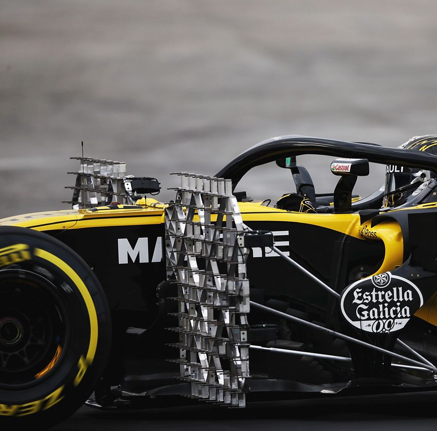
14 www.racecar-engineering.com FORMULA 1 · WINTER 2018Renault RS18 with pressure sensor array. This is highly visible but there might
also be small sensors measuring air pressures that are fitted to the car itself The EvoScann P Series miniature pressure scanner is so small (36mm x 33m x 8mm)
it can be located in areas of a racecar that have previously been impossible to access
MotoGP teams. This compactness –
the 8-channel launch version is just
applications. Traditionally pressure
sensor array and surface pressure
other controlled environments’. It is
a 16-channel device typically used in These enable
36mm (1.42in) x 33mm (1.30in) x 8mm
(0.31in) and weighs only 16g (0.56oz) –
measurement has often been done
with one of the Scanivalve multi-
wind tunnels where installation space
is not an issue, overall length being aerodynamicists
to gather
will enable the sensors to be located in port scanners such as the ZOC (Zero, around 200mm (8in).
areas previously difficult or impossible Operate Calibrate) range of analogue The newest and most advanced
pressure data
to access, such as within front wing devices in 32- or 64-channel form, and Scanivalve product is the MPS
elements or other important small these measure 105mm (4.1in) x 36mm (miniature pressure scanner) range,
aerodynamic parts. 1.4in) x 14mm (0.55in), finding use in a 64-channel high-end device
wind tunnel models and other space- measuring roughly 89mm (3.52in) around and
Pressure change limited applications. x 40mm (1.56in) x 22mm (0.87in),
To see where and how this new
compact pressure scanner fits into
Another oft-used device is the
popular DSA range, described by
several of which might typically
be seen on a wind tunnel model,
on the car’s
the overall scheme of things, let’s
first take a brief look at some of the
Crowhurst as ‘a good workhorse’ and
by Scanivalve themselves as ‘intended
and which is also used in on-car
applications, too. ‘It’s a fantastic
surfaces
complimentary products and their for most laboratory, educational or product,’ says Crowhurst, ‘and the
FORMULA 1 · WINTER 2018 www.racecar-engineering.com 15TECHNOLOGY – PRESSURE SENSORS
Scanivalve MPS Scanivalve DSA3217
4264 pressure pressure scanner
scanner, with
pen for scale
Figure 1: Schematic layout of tube runs in a conventional pressure scanning system
Tubing lengths should be as
short as possible to avoid
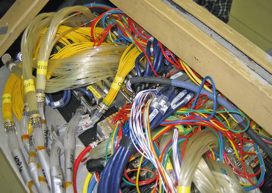
frequency response issues The schematic in Figure 1 might not look so complicated but in reality on a wind tunnel
model (or a racecar) a conventional pressure scanning set-up can look more like this
latest version is a big technical so forth has therefore inevitably usual on-vehicle communication on accuracy, performance, sensitivity
advance over its predecessor as well as been highly compromised by the protocols (CANBus). The scanners and noise insensitivity was great.’
being the most technically advanced, long tubing runs that have been pick up their power supply from the The P8 launch model offers a
fully digital instrument available.’ intrinsically required. communication cable, and feature choice of pressure ranges; at the low
However, on the strength of integral signal conditioning. end of the scale +/-20kPa range is
Tube lengths feedback from customers, Evolution offered with an accuracy of 0.1per
Among the criteria for obtaining Measurements’ concept for the Small and light cent full scale claimed, providing +/-
accurate and repeatable pressure EvoScann P Series was to reduce Gordon says: ‘Our Evoscann P series 20Pa resolution. However, a number
measurements is that tubing lengths the size (and channel count) of the is certainly the smallest and lightest of developments are underway,
should be as short as possible to scanner so that they could be located pressure scanner available and it Crowhurst says: ‘The launch version
avoid frequency response issues, and much closer to where the pressure can be fitted [to measure pressures] was primarily aimed at absolute
should ideally all be of equal length measurements needed to be taken. in places that were previously not surface pressure measurements.
to maintain consistency between The concept of a ‘distributed system’, measurable. It’s been interesting But we will shortly be releasing a
channels. The diagram in Figure 1 shown in Figure 2, was to switch from that the door has been held open differential pressure version which
generically illustrates this challenge. a small number of centrally located wherever we have introduced it, so will measure the difference between
With tightly packaged racecars, multi-channel scanners with complex it’s clearly meeting an un-met need. atmospheric pressure and the [local]
available space for pressure scanners, tubing runs to more scanners with We have presented it to the F1 teams surface pressures creating lift or
associated hardware including power lower channel counts, and to locate and a few others outside F1 and downforce. This will have a choice of
supplies and signal conditioners, the scanners around the car close many have either bought it or asked ranges from +/-7kPa upwards.’
not to mention bundles of tubing, is to areas of interest. for customisations, or want to have it With a similar accuracy to the
clearly at a premium, and options are This vastly reduces the length when we reach the next stages in our launch model this would enable +/-
severely limited within the chassis of a and complexity of the tubing runs roadmap development.’ 7Pa resolution, which would be well
racecar and perhaps other areas within and associated installation, with Gordon also revealed that able to resolve the small variations
the body of a scale wind tunnel model. just a single cable emerging from EvoScann sensors were run on three in surface pressures seen on many
So getting reliable data from ‘outposts’ each scanner to connect with cars in free practice at the last F1 race areas of racecars. However, Crowhurst
such as front wings, endplates and data acquisition systems using the of 2017, and reported that ‘feedback added that ‘sensitivity and resolution
16 www.racecar-engineering.com FORMULA 1 · WINTER 2018TECHNOLOGY – PRESSURE SENSORS
will also improve, we will likely
increase resolution by a factor of
10.’ Further variants with more
channels will also be available; a
16-channel version that fits the same
dimensional envelope will come, and
a 32-channel version that will only be
slightly longer will follow that.
Embedded device
One of the advantages of this slim
pressure scanner is that in some
instances it can be inset into the
surface of the device it is intended
to measure. For example, one F1 Figure 2: A distributed pressure sensor system vastly reduces the length and complexity of the tubing and installation. It puts local
client wanted to attach one to a scanners at the point of measurement, with the tubing installation then connecting via a single CANBus cable to the nearest node
bargeboard. The slender dimensions
of the EvoScann would enable it to scanner inside the small chord front ‘We can even supply the EvoScann and mount the sensor nearby where it
be embedded in the surface of the wing flap elements on an F1 car. And without its carbon composite casing, can be accommodated.’
bargeboard itself and cause negligible in some instances wind tunnel teams which reduces the thickness to just One F1 insider who is familiar
interference with the flows and have used additive manufacturing 4.5mm (0.18in) if the customer wanted with these new sensors says: ‘The test
pressures it was there to measure. methods (3D printing) to provide not an even more compact installation,’ teams are interested in mapping ever
Clearly, the small size of the device only a snug location for the pressure Gordon says. ‘But if there really is an more areas of the car with these small
will enable it to be mounted inside scanner within the test part but also inaccessible location that is too tight sensors. Getting a feel for downforce,
many aerodynamic components to print the tubing runs that connect even for the EvoScann P8 then it is especially at low speed, is better done
to allow the collection and local to the surface pressure tapping ports. possible to run the tubing through it with pressure mapping than with the
conversion of pressure data into four [suspension] pushrod load cells.
electronic signals to be communicated
to the data acquisition system Its slender dimensions would The pushrods have to measure car
weight and take impacts, whereas
enable it to be embedded in the
through just a single cable, rather than pressure sensors can be scaled for the
through many metres of delicate and pressures they have to measure.’
surface of the bargeboard itself
vulnerable small bore plastic tubing. A further interesting feature is
It is even feasible to fit the P Series that because the EvoScann P Series
Pressure scanners
S
imply put, a pressure scanner is data points could be obtained. Nobody Corporation in 1955, and the products including connections, small bore
a device that converts data from else was doing this at the time and it were quickly adopted by the wind tubing, steel tubulations and so
pressure tappings, for example became a huge advantage. tunnel industry. The company forth. Subsequently the company
over a car’s surfaces or from a sensor Pemberton subsequently left developed a large line of products had to adapt to – and exploit – some
array, into electrical signals that can be Boeing and founded Scanivalve to support the use of the scanners, world-changing technological
logged by a data acquisition system.
The concept was devised by one JC
Pemberton, who worked at Boeing In
Seattle, Washington, in the 1950s and
was endeavouring to measure pressures
over aircraft surfaces using lots of liquid-
filled U-tube manometers.
Scanning valve
Not surprisingly it was incredibly
difficult to zero and stabilise all these
devices and to obtain synchronous
data. So Pemberton invented and
developed a motorised, mechanical
scanning valve that multiplexed many
pressure signals into one transducer.
The device was called a scanning valve
because, in essence, the motor drove
the transducer to sequentially scan the
48 ports connected to the valve. It did
this in about 90 seconds, which vastly The original Scanivalve
improved the rate at which pressure
18 www.racecar-engineering.com FORMULA 1 · WINTER 2018than most people need’. Pressure
ranges from +/-20kPa to +/-120kPa
(200-1200mbar or 2.9-17.4psig) are
currently available, with lower ranges
set to become available.
Homologation
As this article was being written
Evolution Measurement was notified
that EvoScann had been homologated
for use with the FIA standard ECU. This
process included, among other things,
being able to demonstrate that, as a
microprocessor-equipped sensor, it
was not possible to re-programme
the device for ‘alternative purposes’,
something it is demonstrably not
possible to do with the single CANbus
Figure 3: Screenshot of EvoScann GUI. Device has an onboard integral microprocessor so the output is in engineering units of pressure communication cable that provides
the power to and data from the
devices have an onboard integral fits most known requirements’ Gordon environmental conditions to be sensor. So prospective customers
microprocessor, the output is directly says. ‘Our aim is to not only fit the handled, although for applications now have the added confidence
in engineering units of pressure, as niche applications where the standard that don’t need it the outer casing can that this compact, innovative new
Figure 3 illustrates. Here the pressure device is most suited but also, where be omitted. The size of the internal pressure sensor has FIA homologation
scale is in mbar but this is configurable required, to customise for bespoke printed circuit board is a key factor for use on their racecars.
via the GUI to the units of choice. requirements. And, for example, the in the dimensions of the sensor; This also means that it will be
The design of the EvoScann price per channel is comparable to the however there is the capability to permissible in FIA-sanctioned events
incorporates temperature correction Scanivalve MPS scanner [mentioned reduce the size and thickness still to run the sensors during qualifying
for each pressure channel. It can be earlier] so it’s a good fit in terms of the further. The in-plane alignment of the and in the races, and not just in test
configured to measure differential applications it can satisfy.’ output tubulations helps to maintain sessions or free practice. Before such
pressures by setting one channel The carbon fibre outer casing, a compact installation. Scanning rates a compact sensor was available,
to measure static pressure. And it combined with the resin potting up to 1kHz per channel are possible, though, this probably wasn’t even
corrects for ambient pressure too. ‘It process enable a wide range of which Crowhurst says ‘is typically faster considered by the race teams.
Evolution Measurement
E
advances. During the 1970s Scanivalve In 1982 Pemberton sold the volution Measurement The company offers sales of the
developed a combination of valving and company to his sons Addison and was founded in July 2016 devices including spares supply,
calibration that was applied to miniature Jim, and around this time PCs started and is located in Andover, consultancy, support, installation,
silicon sensors and used computer landing on all our desks, so the Hampshire, UK. It is staffed by a team service, calibration, repair and
correction of temperature errors. And company developed PC-based data of engineers highly experienced bespoke solutions, as well as now
measurement of individual sensors was acquisition systems which allowed in measurement, instrumentation designing and manufacturing its
now multiplexed electronically, enabling ever faster data sampling rates. and calibration. The team has own new products.
much faster sampling rates. actually been in its current premises, Managing director Crowhurst
Digital age in a previous guise, since 2006 says: ‘we work in various sectors,
In the 1990s Ethernet-based and is now fully focussed on the niche areas especially where, as
communications boosted things, and high-end fluid temperature and a small, responsive company we
in the early 2000s UBS connectivity pressure measurement market. The can provide turn-key solutions for
speeded everything up further, and relationship with Scanivalve in fact multiple applications in building
all the while miniaturisation was goes back to 2001, via the companies design, wind engineering, aircraft
continuing. Originally signal outputs that the current staff used to work at. design, automotive, wind tunnel
were analogue so the voltage signals assessment and models, and of
required conditioning, but now Highly evolved course in motorsport.’ The latter
everything is digital and processed Evolution Measurement now handles includes MotoGP, from where interest
to output in pressure units, and northern Europe-wide factory- is emerging in what is an increasingly
it is possible to take thousands of level calibration, repair and service aerodynamics savvy sport.
readings per second per channel from support for Scanivalve while special There are applications in cycling,
increasingly compact devices. relationships also exist with Guildline too. And the company is also working
Such has been the impact of (as its exclusive UK distributor for on a package for Formula Student.
Scanivalve Corporation that it has precision measurement solutions) Please form an orderly queue …
become the Hoover of the pressure as well as with Meggitt (as its UK Contact: Evolution Measurement Ltd
scanning industry, the generic name application-specific distributors for Tel +44 (0)1264 316470, web:
An advert for the first Scanivalve device most folk reach for when a need arises. dynamic pressure sensors). www.evolutionmeasurement.com
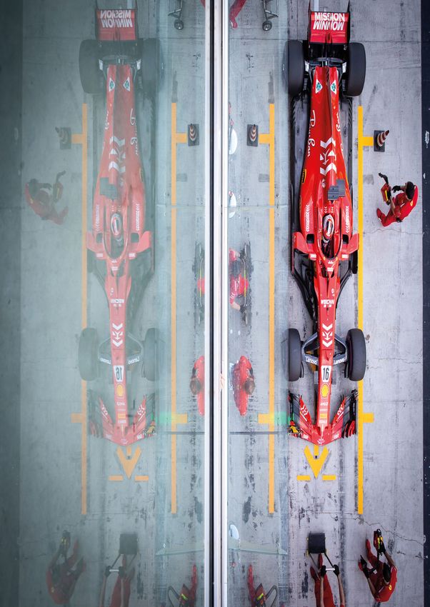
FORMULA 1 · WINTER 2018 www.racecar-engineering.com 19FORMULA 1 2018 – TESTING The reigning champion Mercedes team has taken a conservative approach to Halo, where design and implementation regulations allow some freedom 20 www.racecar-engineering.com FORMULA 1 · WINTER 2018
The Halo effect
Formula 1 2018 hit the ground running in Barcelona with all new Pirelli
compounds, aero and the controversial head protection Halo system
By GEMMA HATTON and SAM COLLINS

F                                                                                                              ‘In testing we will
          ormula 1 has ushered in a host of          is confirmed we’re confident that the parts we’ll
          changes for the 2018 season. The new       bring to the car will sort out those losses.’
          head protection system, known as
          Halo, is the most obvious from a visual
                                                          It is something being worked on right
                                                     up and down the pitlane with lots of airflow              make sure we understand
point of view, and has already attracted a lot of
negative feedback from the teams. It has also
                                                     sensors fitted to cars around the Halo structure
                                                     and downstream of it. ‘Aerodynamically                    that the losses coming
                                                                                                               off Halo are where we
had a significant effect on the rest of the car,     speaking, Halo is certainly not penalty free
in terms of weight and design thanks to a late       and I think there is a challenge there to either
introduction of the regulation leading in some       cope with it in the first instance, let’s call
cases to an all-new chassis design. With new         it damage limitation, and thereafter think                think they are’
tyres from Pirelli, offering teams a new challenge   about opportunity and exploitation,’ Peter
of working them at different circuits, and longer    Prodromou, McLaren’s Chief Technical Officer              ‘It has effects on the cockpit because it is local
life power units for this season, teams have had     for aerodynamics adds. ‘It does open up some              to that opening. You have got the driver in
anything but an easy preparation for the season.     avenues which are possibly interesting to look            there and so you’ve got to make sure you don’t
     The Additional Frontal Protection-Halo (AFP-    at. I am sure there will be a variety of different        have the negative effects there,’ Toro Rosso
Halo, or just Halo) is without doubt the biggest     solutions out there but the scope is quite                Technical Director James Key adds. ‘You’ve
visual change between the 2018 Grand Prix cars       limited to the allowance around the basic                 got effects on the engine air intake and effects
and those used in 2017. In design terms the          shape, but there is opportunity.’                         after that towards the back, so there are a
Halo is governed by its own specific appendix to                                                               number of different things you have to think
the FIA technical regulations. Everything from       Aesthetic gain                                            about. None of them are massive effects but
the shape and dimensions of the device to the        The rules allow a 20mm area of freedom around             they all require some level of attention.’
material it is made from (titanium alloy Ti6Al4V     the titanium structure, introduced partly for                  Fitting the Halo is no easy challenge either;
Grade 5) is defined. However there is still scope    aesthetic reasons but predictably these fairings          not only does the Halo have to be homologated
for different manufacturers to supply their          are being used for aerodynamic gain, as some              independently, it also has to pass crash tests as
own products into the category, though each          teams have added winglets and in one case                 part of the chassis homologation procedure.
must be homologated independently at the             airliner style vortex generators to their Halos.          This has proved to be a major issue for teams.
Cranfield Impact Centre. At the time of writing
three companies had homologated Halos; CP
Autosport of Germany, SS Tube Technology in
England and a third company, V System, from
which each team must purchase their Halos.

Airflow impact
As can be imagined for such a visually obvious
addition to the car, the aerodynamic impact
of Halo is noteworthy, and the teams are
doing what they can to deal with its impact,
particularly on the airflow over the whole car.
    ‘It has a significant downstream effect,
especially round the rear wing area,’ highlights
Andy Green, Technical Director of the team
known as Force India at time of writing (the
team name is likely to change by the first race
in Australia in March). ‘It is not designed to be
an aerodynamic device, so it doesn’t do us any
favours in that department and it requires a lot
of work to mitigate the issues that it causes. In
testing we will make sure we understand that
the losses coming off the halo are where we
think they are from our modelling tools. If that     Toro Rosso is one of several teams to try to increase aero efficiency with its Halo design, one of many to choose this option

                                                                                                             FORMULA 1 · WINTER 2018 www.racecar-engineering.com 21
FORMULA 1 2018 – TESTING
The 20mm area at the top of the Halo has been exploited
differently by the teams. The Haas team has adopted this
toothy solution while others have mounted a wing
everything that moves around – which it is
designed to do – it is a bit scary.’
During the chassis homologation tests the
Halo has to withstand various loads without it or
the monocoque failing. The biggest load applied
to the structure is 116kN from above, which has
to be endured for five seconds. Longitudinal
forces of 46kN and 83kN are applied from the
front as well as a lateral load of 93kN from the
side. For comparison, the roll structure on top
of the car has to withstand 50kN laterally, 60kN
longitudinally and 90kN from above.
Weighty issue
To survive these severe loads, the Halo itself has
become quite a substantial structure, weighing
by regulation 7kg (+0.05kg, -0.15kg). In addition,
the monocoque has also had to increase in
strength significantly to cope with these tests.
This has further increased the weight of the
New rubber from Pirelli is designed to help drivers and teams at ‘We always knew it was going to be a chassis by approximately 12-13kg. Whereas, the
particular tracks. Pressure sensors were all the rage in Barcelona challenge so have invested time and money 2018 technical regulations have only allowed
as teams completed their aero maps during pre-season testing up front to do a lot of test pieces,’ McLaren a minimum weight increase of 5kg to 733kg,
Chief Technical Officer Matt Morris admits. forcing teams to save weight in other areas of
‘It takes the weight of a ‘Obviously, you don’t want to build a complete
chassis but we built a few test pieces with
the car. Interestingly, now at the start of a race a
2018 Formula 1 car will weigh roughly the same
London bus and when dummy Halos and parts of Halos to test how
the interfaces would behave and we found
as a non-hybrid LMP1 in qualifying trim.
‘From a design perspective, weight is a big
you see that test going some issues. It was close, we didn’t breeze
through and there were some heart-stopping
part of it. The weight limit did go up, but not by
nearly as much as the installation weight of the
with that amount of load,
moments with particular static tests coming halo so it put additional stress on all the other
in from an oblique angle. It takes the weight parts of the car,’ Green continues. ‘We had to try
it is a bit scary’
of a London bus and when you see that to optimise the weight in those areas to try and
test going on with that amount of load and keep the weight limit below the minimum so
22 www.racecar-engineering.com FORMULA 1 · WINTER 2018Short sidepod concept
I
n 2017 Ferrari introduced a new short sidepod concept,
relocating the upper side impact structure (a single
specification design shared by all teams) and moving
the main cooling aperture rearward. A set of box shape
aerodynamic elements forward of the duct ensure rules
compliance. Ferrari took this approach for aerodynamic
reasons rather than those of cooling. In 2018, half the grid
featured the same solution, but not all teams agree that it
is the right route, with Mercedes, Renault, Force India and
others all opting against adopting the concept.
Conservative approach Sidepod design seems to be led by Ferrari, with impact structure relocation for efficient aerodynamic effect
‘Everything you do in aerodynamics has an opportunity
cost; there is much more opportunity to make the car worse
than better,’ claims Mercedes Technical Director, James
Allison. ‘If you want to pursue a new and different concept,
you will expect to find a fair amount of loss before you
get back into positive territory. We looked at that concept
and felt it would spend too much time being in negative
territory before it would perhaps offer any gain at all. If you
are a [team] that is a long way down the grid the situation is
different it is worth taking that gamble, as you have less to
lose and you know that the path you are on is not right.’
It is likely that the relocation of the side impact structure
would require a substantial change to the monocoque
design, while getting adequate airflow into the cooling
system with such a complex arrangement of aerodynamic
elements around the leading edge of the sidepod duct is
also likely to be a major challenge. Mercedes has not adopted this same approach, believing that too much time would be lost in development
that we can run ballast because the other area
that we have to bear in mind is we have to hit
a weight distribution target as well.’
Although it was originally introduced as
a temporary measure to help Pirelli develop
tyres when it became the sole tyre supplier in
2011, the technical regulations still limit every
car in terms of weight distribution, with just a
7kg window of freedom. This means that while
some teams may be able to build a car under
the minimum weight, they cannot get it fully
within the distribution window.
Halo kitty
‘You only have a very small window of weight
distribution so the actual architecture of the
car needs to be correct to start with, otherwise
you’re adding ballast to a car that doesn’t
need ballast just to get the weight distribution
right,’ Green says. ‘We would have loved to
have added a huge safety margin to the whole The loss of the T-wing is not total; some teams are trying to recover some of the effect with lower mounted winglets
design so that we would happily sail through
the crash and load tests without any issues but
that wasn’t possible because the weight limit of
rear end of its car as a result, abandoning its
cast titanium gearbox casing (something it ‘You have a small window
the car didn’t go up enough. We couldn’t afford
to increase the base weight of the car more
has evolved over many seasons) in favour of
a composite transmission. of weight distribution so
the architecture of the car
than a few kg because we knew we only had a While the price of the Halo itself is relatively
few kg that wecould take out of the car. It was, modest, the cost of developing a chassis to fit it
needs to be correct’
structurally, incredibly challenging.’ is higher than some of the smaller teams would
This weight challenge has seen at least like. This cost was worsened by the late decision
one team, Renault, substantially rework the to adopt the Halo as the 2018 AFP solution, with
FORMULA 1 · WINTER 2018 www.racecar-engineering.com 23FORMULA 1 2018 – TESTING
With only a 7kg weight distribution, teams have struggled to get the weight down and remain in the window; Renault adopted a composite gearbox casing to reduce weight
teams only informed of this final decision in as it is much lighter than Halo with lower The significant aerodynamic changes of
September, 2017 after a long discussion process. requirements on the chassis structure. the 2017 regulations resulted in an increase in
‘Expense-wise it’s huge because we had to The weight increase as a result of the Halo loads of over 20%, demanding the tyres to be
do a new chassis. We wouldn’t have anticipated also places an additional demand on the four extremely robust, leading Pirelli to ramp up the
doing a new chassis this year given the number power unit suppliers, which have also had to stiffness of their entire compound range. Pirelli
of changes we made last year. For a team like increase the life of their power units. Teams can also had to develop tyres with little knowledge
us we would look to try and get two years out now only use three combustion engines (ICE), of the potential performance that the teams
of the chassis if possible. So in that respect three MGU-H’s and three turbochargers (TC) could achieve in 2017. Despite 12,000km of
it cost us a huge amount to redevelop and during the season, compared to four last year. testing, the 2014 adapted ‘mule’ cars that Pirelli
redesign the new chassis. It is in the hundreds That’s 2,100km of racing mileage not including used to develop the 2017 compounds only
of thousands, if not million dollar mark, to put practice sessions or qualifying. Whereas the achieved a 10% increase in downforce and
the Halo on the car for us,’ says Green. energy stores (ES), control electronics (CE) and therefore the results were unrepresentative
MGU-K’s are all limited to two per season, or and inconclusive. To cope with this, Pirelli went
Screening process 3,150km of racing. This demand for increased for a conservative approach last year, and
The Halo has had a largely negative reception reliability will no doubt have forced the having tried and tested their designs for an
from drivers, teams, the media and fans. This suppliers to manufacture more robust units, yet entire season, the 2018 range is a slightly more
has lead to work continuing on alternative they have had to minimise weight to help teams aggressive evolution of 2017.
additional frontal protection systems. In comply with the minimum weight regulations
2017 a brief test run was conducted with which have been challenging to achieve with Compounding issues
a clear windscreen fitted to a Ferrari, but the consequences of Halo. It remains to be seen ‘The 2018 compounds are from the same family
while this solution solved the frontal impact how successful they have been. of compounds as 2017,’ explains Mario Isola,
requirements, the driver complained of Sporting Director of Pirelli. ‘The reason why
visual distortion. However, Indycar is now Tyre dilemma degradation was so low last year was because
experimenting with a similar aeroscreen The other major changes for this year come these compounds have less surface overheating
solution (see p16). Teams prefer the windscreen from the tyres. To encourage overtaking and pit and in general behave in a different way. In
option not only for aesthetic reasons but also stops, Pirelli have added two more colours, and particular we used the 2017 Soft as a baseline
therefore compounds, to their tyre compound [for 2018] because last year the Soft had a
‘We used the 2017 Soft as rainbow, the Superhard and the Hypersoft, as
well as making the entire range a step softer,
wider working range compared to the other
compounds. Last year’s Soft is now the Medium.’
a baseline because last and introducing new allocation rules. The
Superhard is now the hardest compound,
From there, the 2017 Soft ‘baseline’ was
then developed and used to create this year’s
year the Soft had a wider
adopting the conventional orange colour of softer compounds (Soft, Supersoft, Ultrasoft
the Hard, which has now become the light and Hypersoft), each decreasing in stiffness in
blue, and the Hypersoft is the softest compound relatively consecutive steps. Although Pirelli,
working range compared and is light pink in colour. However, to gain a along with some drivers, have commented
full understanding of these additional that the softer compounds of the 2018 range,
with the other compounds’ compounds we need to reflect on 2017. tested at Abu Dhabi last year were ‘much closer
24 www.racecar-engineering.com FORMULA 1 · WINTER 2018You can also read