Gas detector Based on infrared technology Model GIR-10
←
→
Page content transcription
If your browser does not render page correctly, please read the page content below
SF₆ gas solutions
Gas detector
Based on infrared technology
Model GIR-10
WIKA data sheet SP 62.02
Applications
■ Locating and quantifying leakages at SF6 gas filled equip-
ment
■ Determination of leak rate for final inspection of SF6 gas
filled equipment
Special features
■ Smallest concentrations of up to 0.6 ppmv can be detected
■ Responds only to SF6 gas and is therefore not sensitive to
humidity and common volatile organic compounds (VOC)
■ Easy to use
■ Fast response time
■ Calibration in the factory using certified test gases
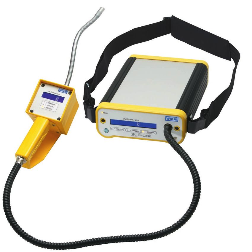
Gas detector model GIR-10
Description
The gas detector model GIR-10 is used for the detection A pump in the console case provides continuous flow of the
of the smallest SF6 gas concentrations and is thus ideal for sucked-in gas mixture through the sample chamber of the
detecting the place and size of leakages. infrared sensor.
Infrared technology If the SF6 gas is already present in low concentrations in the
The GIR-10, which is based on the non-dispersive infrared measurement environment, this offset can be tared to 0 ppmv
technology (NDIR), offers fast response times and reliable at the instrument. It makes the leakage detection easier,
measured values even in case of small leakages. as every measured value greater than 0 ppmv represents
leakage.
Simple operation
This instrument is characterised by simple handling and Depending on the version, model GIR-10 sends an acoustic
good readability. Both the hand-held instrument and the alarm when a defined concentration is exceeded.
console case are equipped with a digital indicator which is
easy to read. This allows reading the current SF6 gas values
from any position.
The leakage detection is carried out using a hand-held
instrument which has a movable gooseneck with gas inlet on
the front side. An exchangeable filter prevents particles from
being sucked in, thus protecting the infrared sensor.
WIKA data sheet SP 62.02 ∙ 02/2020 Page 1 of 5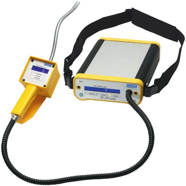
Measuring principle
Non-dispersive infrared technology (NDIR) In the gas detector model GIR-10, the sucked-in air is
Non-dispersive infrared sensors are opticalsensors which are pumped through the sample chamber. The concentration of
often used in the gas analysis. SF6 gas is determined electro-optically by means of absorp-
tion of SF6 at 947cm-1. The output signal of the detector is
The most important components are the infrared source, a directly proportional to the absorption of the infrared light
sample gas chamber, a wave length filter and an infrared at the specific wave number. The GIR-10 does not need
detector. consumables and is maintenance-free within the calibration
cycle.
Infrared source Sample gas Wave length Infrared
chamber filter detector The Lambert–Beer law
Φ
Α= −lg =ε∙c∙l
2,500 cm-1
Φ0
A: Absorption
Infrared ray Φ: Light intensity after absorption of SF6 gas
Φ0 Φ0: Light intensity without absorption
ε: Extinction coefficient
Infrared ray c: Concentration
Φ l: Length of the irradiated chamber (sample gas chamber)
947 cm-1
Instrument construction
Gas inlet with particle filter
Digital indicator of the hand-held instrument
Connection of the connection hose to the hand-held
Connecting hose
On/Off switch, zero point setting
Digital indicator on the console case
Connection of the connection hose to the console case
Console case
Shoulder strap
WIKA data sheet SP 62.02 ∙ 02/2020 Page 2 of 5Specifications
General specifications
Measurement principle Non-dispersive infrared technology (NDIR)
Voltage supply ■ Lithium-ion rechargeable battery for approx. 8 h operating time
■ Charger AC 100 ... 265 V, 50/60 Hz
Calibration sequence After 1,200 hours of operation or every 2 years at the latest
Permissible temperature ranges
Storage temperature -10 ... +60 °C
Operating temperature 0 ... 50 °C
Dimensions
Console 285 x 195 x 80 mm
Hand-held 210 x 110 x 90 mm
Weight
Console 2.5 kg
Hand-held 0.5 kg
Sensor specifications (SF₆ gas version, 0 ... 2,000 ppmv)
Area of application Leak detection
Medium to be measured SF₆ gas
Measuring range 0 ... 2,000 ppmv
Detection limit 1) 3 ppmv
Detectable leak rate (calculated) 3 g/year (corresponds to 1.81 x 10⁻⁵ mbar x L/s)
Accuracy 2)
≤ 100 ppmv ±3 ppmv
≥ 100 ... ≤ 2,000 ppmv ±2 % of end value
Resolution 1 ppmv
Measuring units ppmv, g/y, cc/s
Response time T90 < 1 second
Alarm signal Visual and audible
1) No cross-sensitivity to typical volatile organic compounds (VOC).
No influence of air humidity between 0 ... 95 % r. h. (non-condensing).
2) max. drift of 0.05 % per month
Sensor specifications (SF₆ gas version, 0 ... 50 ppmv)
Area of application Integral leak testing
Medium to be measured SF6 gas
Measuring range 0 ... 50 ppmv
Detection limit 1) 0.6 ppmv
Detectable leak rate (calculated) 0.34 g/year (corresponds to 1.81 x 10⁻⁶ mbar x L/s)
Accuracy
≤ 10 ppmv ±0.5 ppmv
> 10 ppmv ±2 %
Resolution 0.1 ppmv
Measuring units ppmv, g/y, cc/s
Response time T90 < 12 seconds
Alarm signal Visual and audible
1) No cross-sensitivity to typical volatile organic compounds (VOC).
No influence of air humidity between 0 ... 95 % r. h. (non-condensing).
WIKA data sheet SP 62.02 ∙ 02/2020 Page 3 of 5Sensor specifications (version CO2, 0 ... 500 ppmv (Clean Air / Dry Air))
Area of application Integral leak testing
Medium to be measured Clean Air / Dry Air / CO2
Measuring range 0 … 500 ppmv
Detection limit 1) 10 ppmv
Detectable leak rate (calculated) 3.43 g/year (corresponds to 1.81 x 10⁻⁵ mbar x L/s)
Accuracy 400 ppmv ±50 ppmv
Resolution 1 ppmv
Meauring unit ppmv
Response time T90 < 1 second
Alarm signal Visual
1) No cross-sensitivity to typical volatile organic compounds (VOC).
No influence of air humidity between 0 ... 95 % r. h. (non-condensing).
Dimensions in mm
Console
WIKA data sheet SP 62.02 ∙ 02/2020 Page 4 of 5Hand-Held
Accessories and spare parts
Description Order number
Particle filter 14005140
Transparent filter cap 14005999
O-ring 14004754
Measuring tip with injection needle 14093643
Sampling bag 5 litres 14029961
Ordering information
Model / Measuring range / Unit / Accessories and spare parts
© 2013 WIKA Alexander Wiegand SE & Co. KG, all rights reserved.
The specifications given in this document represent the state of engineering at the time of publishing.
We reserve the right to make modifications to the specifications and materials.
02/2020 EN
WIKA data sheet SP 62.02 ∙ 02/2020 Page 5 of 5
WIKA Alexander Wiegand SE & Co. KG
Alexander-Wiegand-Straße 30
63911 Klingenberg/Germany
Tel. +49 9372 132-0
Fax +49 9372 132-406
info@wika.de
www.wika.deYou can also read