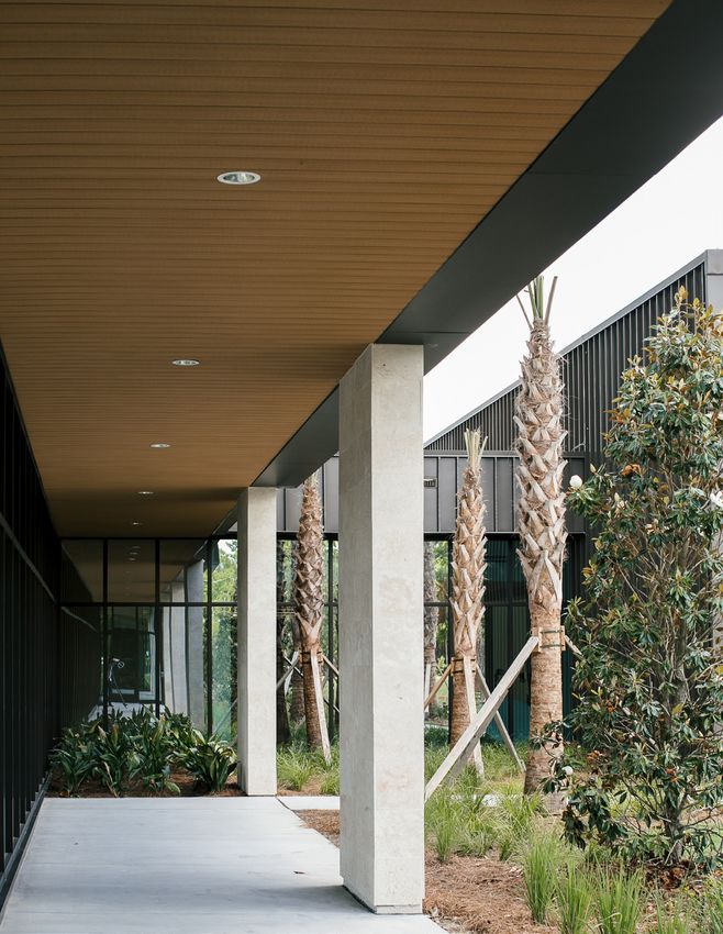
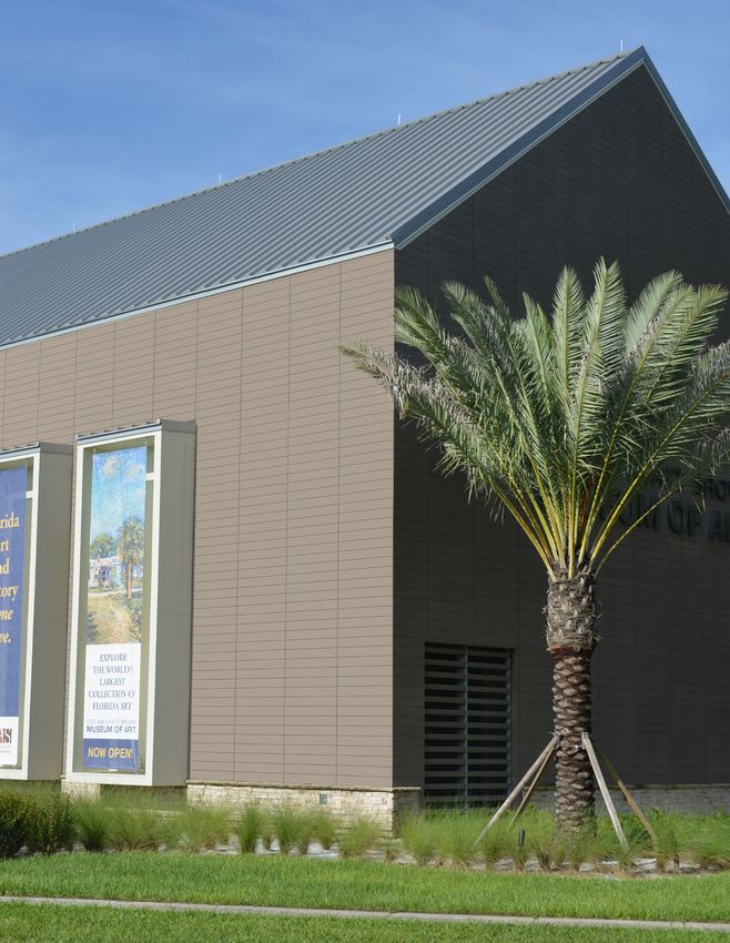
GEOLAM RAINSCREEN CLADDING/SOFFIT
←
→
Page content transcription
If your browser does not render page correctly, please read the page content below

GEOLAM RAINSCREEN CLADDING/SOFFIT
PROJECT:

COMPANY:

GENERAL CONTRACTOR:

ARCHITECT:

LOCATION:
GEOLAM RAINSCREEN CLADDING/SOFFIT
TABLE OF CONTENTS

1. Vertigo 5010 Installation Guide
2. Product Specs/Data
3. Geolam Warranty
INSTALLATION GUIDE

Geolam Vertigo 5010
Cladding & Soffits
                     www.geolaminc.com
Vertigo 5010
     Hybrid Aluminum/WPC Cladding/Soffit
     Datasheet

                                                     71/4”/ 184 mm
                                                     61/4”/ 160 mm
1
    /2”/ 13 mm

                                 Technical information may change without warning.
           Please ensure you that you reference our latest as shown on our website at www.geolaminc.com

Thickness: 1/2 in | 13 mm                                  Secondary moment lx (cm4): 0.56
Total width: 7 1/4 in | 184 mm
Usable width: 6 1/4 in | 160 mm                            Secondary moment ly (cm4): 122.03
Section tolerances in mm: + 0.5 / - 2.0                    Section modulus Z+x (cm3): 0.68
Fire rating:                                               Section modulus Z-x (cm3): 0.68
On request before order
                                                           Section modulus Z+y (cm3): 13.47
Surfaces finish: Sanded
                                                           Section modulus Z-y (cm3): 13.47
Profiles fastening and installation:
Check our website www.geolaminc.com                        Core in anodized aluminum alloy:
                                                           A6063S-T5 Serie 6000
Standard length: 12 ft | 3.66 m
                                                           Coefficient of Thermal Expansion (20-100°C):
Or order custom lengths from:
                                                           23.4 μm/m/°C
7 ft to 19 ft 8 in | 2.15 m to 6 m
                                                           Modulus of Elasticity: 68.9 GPa
Weight: 0.80 lb/ft | 1.19 kg/m
                                                           Max Tensile Strength: 186 Mpa

                                                           Carbon Footprint:
                                                           WPC : 1.54 kg CO2 /Kg
                                                           Profile : 9.005 kg CO2 /Kg

                               Sanding finish and/or shading may vary between runs

Standard Colors -                      Minimum 5,000 ft for all colors

                                                 All standard colors stocked in the US, no minimum.

Teak                     Moleskin                      Rosewood                      Ebony

Non-Standard Colors - 90 day lead time - Minimum order 5,000 ft.

Ivory                    Blackwood                     Bilinga
                                                                                                          2
Custom Colors Available - Minimum order 6,000 ft.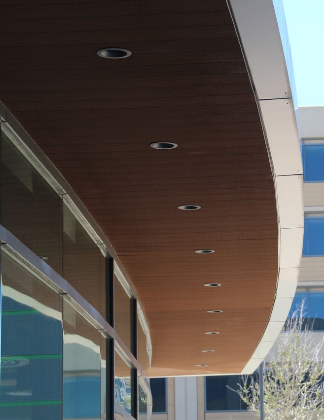
Vertigo 5010
WHS: Wood hybrid system
Datasheet
Drainage Drainage
Plane Plane
advised advised
Minimum 3 mm | 1⁄8 in
Maximum 12 mm | 7⁄16 in
1. Weeping of condensation and air 4. Recommended screws are stainless
circulation are essential to the health steel, with an austenitic structure and
of building products. Allthough the non-magnetic. Recommended screw
boards can be mounted directly diameter is 4 mm, pan head with a
onto the wall or substrate, it is good diameter of 8.2 mm and length of
building practice to install a drainage 19 mm. Maximum 24”o.c.
plane and mount onto that. Do not
5. We recommend leaving a 3 mm (1/8”)
seal the top nor bottom of the wall to
gap between butt ends to allow for
allow for drainage and air circulation.
OUTSIDE CORNER TRIM expansion/contraction in response to
2. Geolam boards can be mounted changes in temperature. However, if
horizontally, vertically,
/ ”/ 14 mm
or/ ”/diagonally your design calls for zero-spaced butt
1
3 mm 2
1
8
directly onto the wall. Over code joints, please refer to Page 9.
compliant AVB.
6. The boards may be miter-cut for
3. Boards may be ripped (cut along outside corners or Geolam O/S
2”/ 50 mm
their length) as needed. corners may be used.
1”/ 25 mm
1
/2”/ 14 mm
6. Exposed screws on the final board may
1
/8”/ 3 mm
be covered with caulking if desired or
1”/ 25 mm
our color-matched 2-piece starter/’J’
trim as shown below.
2”/ 50 mm
2-Piece Starter (J-trim) 9321
J TRIM (2-PIECE STARTER STRIP)
/2”/ 14 mm
1
/4”/ 5 mm
1
1 1/4”/ 30 mm
/4”/ 20 mm
3
Outside Corner
OUTSIDE CORNER TRIM 9322
1
/2”/ 14 mm 1
/8”/ 3 mm
2”/ 50 mm
1”/ 25 mm
/2”/ 14 mm
1
1
/8”/ 3 mm
1”/ 25 mm
3
2”/ 50 mm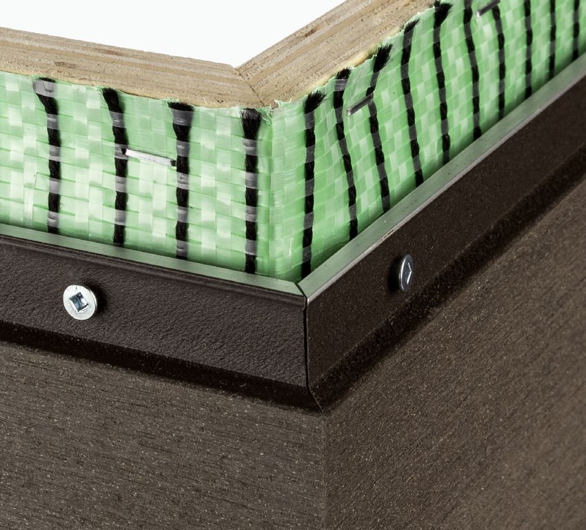
advised                                               advised

Vertigo 5010

                                  Minimum 3 mm | 1⁄8 in

                                                                                   Maximum 12 mm | 7⁄16 in
 Drainage planes
 Drainage planes are water repellent materials that are located behind the cladding and are
 designed and constructed to allow airflow and water drainage.

                                                             Kingspan GreenGuard MAX Building Wrap

 Some drainage plane manufacturers:
 • Tyvek Stucco wrap
 • TYPAR® Drainable Wrap
 • HydroGap® Drainable Housewrap
 • Kingspan GreenGuard MAX Building Wrap

 Installation videos
 Click here to watch videos on how to install Vertigo 5010 with a drainage plane or
 furring strips

                                                                                                             4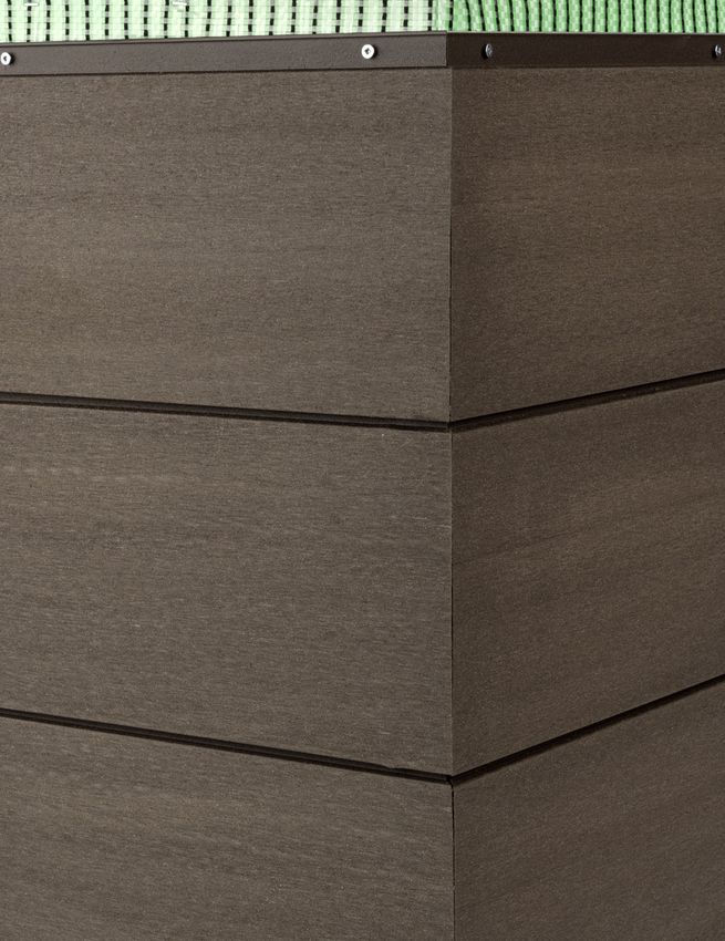
Vertigo 5010
             Installation of J-trim                                                      1
                    ‘Part A’

                                                                              1
                                                                           /2”/ 14 mm
                                              /16”
                                              7

                    ‘Clip’                   11 mm
             ‘Part A’

                                                                 1
                                                              /2”/ 14 mm
                  ‘Part B’          /16”
                                    7

               ‘Clip’              11 mm

                                                                              1
                                                                           /4”/ 5 mm
                                      3
                                       /4”/ 20 mm
             ‘Part B’                      1 1/4”/ 30 mm                                                  Part A
                                                                                                                                             Ver

                                                                 1
                                                              /4”/ 5 mm
                             3
                              /4”/ 20 mm
                                                                                                                                        Vertigo 5
                                 1 1/4”/ 30 mm                                          1. F       PartAAof the J-trim to the wall as
                                                                                            asten Part
                                                                                           shown (ss screws recommended)

             2                                                                           3

                                                                                                             Clip    Clip
                                 VertigoVertigo
                                         5010 5010
 A Part A
                                                                                                            Part B Part B
                                            Clip
go 5010     2. S
                crew the Geolam Vertigo board through                                  3. A
                                                                                            ttach the metal clips onto Part B every
               the J-trim into the wall every 24”                                          16” (40 cm) as shown
                                           Part B

             4                                                                           5

                                                                                                           Part A Part A
                                                                                                           Part B Part B

                                           Part A          Clip
  Vertigo 5010                             Part B
                                                       Part B

            4. With a rubber mallet tap Part B into Part A                             5. Final assembled J-trim

                                                                                                                                        5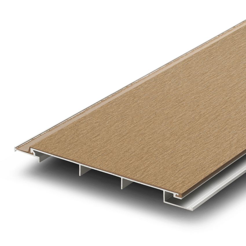
advised advised
Minimum 3 mm | 1⁄8 in
Maximum 12 mm | 7⁄16 in
Vertigo 5010
Cladding Installation
1. Install 2-Piece Starter/”J” or other trim
component at top and bottom of wall (A)
2. If outside corners are not mitered, install A B
Outside Corners before cladding (F)
3. Install top course first panel and screw at
maximum 24” (B)
4. Install next panel with selected joint reveal
gap and secure (C)
Drainage Drainage Drainage Drainage
Plane leaving 1/8” or 3mm
5. Install adjacent panels Plane Plane Plane
advised
Plane
Drainage
advised
Plane
Drainage
between butt jointsadvised advised advised C
advised D
6. C
ut last panel as needed to fit into “J”/
Starter Trim and secure (E)
Drainage Drainage
Plane Plane
Minimum 3 mm | 1⁄8 in
Minimum 3 mm | 1⁄8 in Minimum 3 mm | 1⁄8 in
Maximum 12 mm | 7⁄16 in
Maximum 12 mm | 7⁄16 Maximum
advised advised
advised advised
Plane
Drainage Drainage
Drainage Drainage
Minimum 3 mm | 1⁄8 inMinimum 3 mm | 1⁄8 in Plane Plane
advised E
advised F
Minimum
Maximum 12 mm | 7⁄16 in
advised
Plane 3 mm | 1⁄8 in
Drainage
Plane
Soffit Installation
in
Minimum 3 mm | 1⁄8 in
1. Install 2-Piece Starter/”J” at perimeter
terminations (G)
advised
Plane
Drainage
G H
12 mm | 7⁄16 in
Maximum 12 mm | 7⁄16Maximum
in 12 mm | 7⁄16 in
2. Install first course into trim component and
secure into place (H)
3. S
lide adjacent panels with selected joint
reveal gap and secure (I) ⁄ in
18
4. Install
adjacent panels leaving 1/8” or 3mm
between butt joints
Maximum 12 mm | 7⁄16 in I J
5. C
ut last panel as needed to fit into “J”/
Starter Trim and secure (K)
K 6 | 7⁄16 in
Vertigo 5010
  Cladding – Vertical Orientation
  Wall Detail (Plan View)

                                                      GEOLAM 'J' TRIM
                                                      9321

 GYPSUM BOARD
                                                      VERTIGO 5010
                                                      WALL CLADDING

 ***NOTE***

                                                DESIGNED FROM
                                                REVEAL CAN BE

                                                 3 mm to 12 mm
 TYPICAL WALL
 SECTION FOR
 COMMERCIAL
 CONSTRUCTION.

 CONSTRUCTION
 DESIGN MAY VARY.
 COMPLY WITH ALL
 LOCAL AND NATIONAL
 BUILDING CODES.

                                                      DRAINAGE PLANE
                                                      ADVISED

                                                      WALL BY OTHERS

                                                                        7

Geolam
                           VERTIGO 5010             08.05.2019
                      VERTICAL ORIENTATION
                      WALL DETAIL - PLAN VIEW       6" = 1'-0"
Vertigo 5010
  Cladding – Horizontal Orientation
  Wall Detail (Plan View)

                                                     GEOLAM 'J' TRIM
                                                     9321

 GYPSUM BOARD
                                                     VERTIGO 5010
                                                     WALL CLADDING

                                               DESIGNED FROM
 ***NOTE***

                                               REVEAL CAN BE

                                                3 mm to 12 mm
 TYPICAL WALL
 SECTION FOR
 COMMERCIAL
 CONSTRUCTION.

 CONSTRUCTION
 DESIGN MAY VARY.
 COMPLY WITH ALL
 LOCAL AND NATIONAL
 BUILDING CODES.

                                                     DRAINAGE PLANE
                                                     ADVISED

                                                     WALL BY OTHERS

                                                                       8

Geolam
                           VERTIGO 5010            08.05.2019
                      HORIZONTAL ORIENTATION
                            WALL DETAIL            6" = 1'-0"
Vertigo 5010
Soffit (Plan View)
STRUCTURE BY OTHERS
GEOLAM 'J' TRIM 9321
REVEAL CAN BE
DESIGNED FROM
DRAINAGE PLANE
WALL CLADDING
3 mm to 12 mm
VERTIGO 5010
ADVISED
9
Geolam VERTIGO 5010 08.05.2019
SOFFIT 6" = 1'-0"Vertigo 5010
Alternative butt joint - zero spacing
3 boards mounted horizontally
Alternative butt joints - zero spacing
3 boards mounted horizontally
Please allow
gap for board
to expand Zero spaced Holes 2 ft apart Zero spaced
butt joint butt joint End View
General principles -
1. fix mid-point of middle board and provide
oversized holes for all the other screws to
allow for expansion/contraction
2. Allow outer edges of the outer boards
5 mm each (1/4”) for expansion either into
trim or beside an architectural feature
2-piece Oversized holes Fixed Point in the Middle Oversized holes
J-trim (6 mm) #6 screw (6 mm)
(Pan head with a diameter of 8.2 mm & 4 mm shaft)
Outside boards expand into trim pieces or beside an architectural feature
10Vertigo 5010
Mitered corner
Warning: mitered corners may be sharp!
Solid Substrate
e.g. OSB Plywood
Drainage Plane
e.g. Kingspan GreenGuard® MAX
Building Wrap
#4 Stainless Steel Screw
Geolam Vertigo 5010
11TECHNICAL DATASHEET
Vertigo 5010 CLADDING CO-EXTRUDED FOR
EXTERIOR RAINSCREEN
71/4”/ 185 mm
1
/2”/ 13 mm
Vertigo 5010 Alu/WPC
Thickness 1/2“
Width 7 1/4”
Length 12 ft
Weight/board 9.60 lbs
Colors Teak, Moleskin, Rosewood, Ebony
Maximum distance between supports 24”Geolam, Inc.
9 Shorncliffe Ave., Toronto, ON Canada M4V 1S9
Tel: 416-548-7450 • info@geolaminc.com
www.geolaminc.com
10-YEAR LIMITED WARRANTY
Extent of coverage:
This warranty is given to the original Purchaser of GEOLAM® wood plastic composite decking and/or cladding boards and/
or hybrid aluminum/wpc boards. This warranty does not extend to fasteners that are not supplied by the boards’ manufac-
turer.
Geolam, Inc. guarantees the Purchaser that, for a period of ten (10) years (the term) from the date of the original
purchase, under normal use and service conditions, the GEOLAM® decking and/or cladding boards and/or hybrid
aluminum/wpc boards be free from material defects in workmanship and materials, and will not split, splinter, rot
or suffer structural damage from termites or fungal decay.
If such a defect appears during the term, Geolam, Inc. will, at its option, supply replacement product (but not
the labour cost, freight, taxes or other expenses associated with de-installation and reinstallation) or refund the
purchase in an amount not to exceed Manufacturer’s cost of material.
How To File A Warranty Claim:
Purchaser must notify Geolam, Inc. in writing within thirty (30) days after the appearance of the defect, but no later than the
end of the Term.
Purchaser shall send a brief written explanation of the defect, along with dated proof of purchase to Geolam, Inc.,
9 Shorncliffe Avenue, Toronto, ON, M4V 1S9. Manufacturer reserves the right to request additional information,
including, but not limited to, photos, and to conduct a field inspection.
Exclusion of limited warranty:
This limited Warranty does not cover product failure, product malfunction or any damages resulting from:
(a) improper installation of GEOLAM® products and/or failure to comply with Geolam, Inc.’s installation instructions
(b) beyond normal use, or in an application not recommended by Geolam, Inc.’s installation instructions and local building
codes;
(c) m
ovement, distortion, collapse or settling of the ground or the supporting structure on which GEOLAM® products are
installed;
(d) any act of God (such as flooding, hurricane, earthquake, lightning, etc.), environmental condition (such as air
pollution), or staining from foreign substances (such as dirt, grease, oil, etc.);
(e) variations or changes in color of GEOLAM® products;
(f) n
ormal weathering due to exposure to sunlight, moisture, and atmosphere, and accumulation of dirt or stains;
(g) damages of any kind caused by animals, domestic or otherwise;
(h) improper handling, storage, abuse or neglect of GEOLAM® products by Purchaser, or third parties;
(i) any fasteners not supplied by Geolam, Inc.; and
Failure to strictly adhere to Manufacturer’s written instruction manual for the installation, use or maintenance of GEOLAM®
will render this Limited Warranty null and void.
Limitations of remedies and exclusion of consequential and incidental damages
To the extent permitted by law, Geolam, Inc.’s liabilities are limited solely and exclusively to the obligations specifically
specified herein and under no circumstances will Geolam, Inc. be liable or obligated for any incidental, consequential, indi-
rect, special, punitive or any other damages of any kind whatsoever.
This writing is understood and intended to be the final expression of the parties’ agreement and is a complete
and exclusive statement of the terms and conditions with respect thereto, superseding all prior agreements or
representations, oral or written, and all other communication between the parties relating to the subject matter of this
agreement. No agent, employee or any other party is authorized to make any warranty on behalf of Geolam, Inc. in addition
to that made in this agreement.
This warranty is effective for purchases made on or after May 1, 2011.You can also read