Window Intercom System - Speaker and Microphone Pod - STS-K071 - Installation & User Guide
←
→
Page content transcription
If your browser does not render page correctly, please read the page content below
Window Intercom System
Speaker and Microphone Pod - STS-K071

        Installation &
         User Guide
              December 2020
Contents
Product Overview 3
Components 3
Connections 4
Installation Instructions 5
Speaker & Microphone Kit Installation 6
Staff Side Installation 6
Customer/Visitor Installation 7
Hearing Loop Installation 9
Amplifier Setup 10
Troubleshooting 12
Engineer’s Mode 13
Contacta has a policy of continuous product development, and therefore small specification
changes may not be reflected in this manual. Images, labels, packaging, accessories and
product colors are subject to change without notice.
2Product Overview
Window intercom systems provide assistance for clear communication where
normal speech is impaired by use of glass, a security screen or other similar
barriers.
There is an optional hearing loop facility, providing additional assistance for
hearing device wearers.
Speaker & Microphone Components
1. Speaker Pod
2. Mouse Microphone
3. Staff Pod
4. Double-Sided Fixing Pad
3
1
2
4
General Components
1. Installation and User Manual 4. Power Supply
2. Amplifier 5. Hearing Loop Aerial
3. IEC Lead (optional)
5
1
2 3
4
Fixing Kit:
• Adhesive Clip x 10
• No.6 x 1/2” Countersunk Screws x 15
• P-Clips x 6
3Connections
Power input
connection
Use power supply
through ground
supply only
Hearing loop aerial Staff microphone
Customer/visitor speaker Customer/visitor microphone
Staff speaker Confidence LED (if required) for status alerts
and fault detection
Line in connection for
external audio source LED connection or alert tone (if required)
Confidence LED to confirm the system is powered
or an alert tone for the attention of staff
4Installation Instructions
We recommend that installation is carried out by a qualified engineer,
adhering to relevant standards.
Check the contents of the box to familiarise yourself with the components.
Staff Counter Side
Staff Pod
Mouse Microphone
Speaker Pod Customer / Visitor
Counter Side
Recommended Tools
A basic toolkit recommended to install the system will include:
• Screwdrivers (Flat or Blade 2.5mm • Wire Cutters/Strippers
and Phillips Head PH2) • Tape Measure
• Battery or Mains Drill • Pencil or Marker Pen
• Drillbits: 2mm, 3mm, 5mm and 7mm • Cable Ties
• Cable Tacking Gun (10mm) • Trunking
Trim cables if necessary (excluding the power supply)
to the required length to connect to the back of the
amplifier. Bare approximately 6mm of the cable ends to
connect to the 2 pin plugs.
Negative -
or screened cable
Positive +
5Amplifier Installation
Fixing points
1. Place the amplifier under the staff counter, ensuring that it will not
obstruct staff when they are sitting.
2. Mark the four fixing points for the amplifier under the counter.
4. Drill and fix the amplifier in place using the supplied screws.
6. Install the amplifier’s power supply close to a power socket outlet using
the supplied mounting bracket and fixing screws.
6Microphone & Speaker Installation
1. Place the staff pod on the staff side of the counter top, ensuring it does
not cause an obstruction and is as close to staff as possible.
2. Place the speaker pod on the customer side of the counter top, ensuring it
does not cause an obstruction.
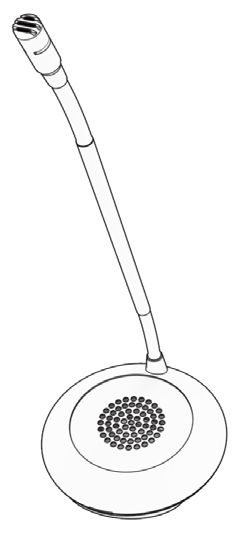
3. Place a mouse microphone on the customer/ Mouse microphone direction
visitor side of the counter top, ensuring it
does not cause an obstruction and is as close
to customers/visitors as possible.
For best performance all mouse microphones
should be fitted facing the user as shown in
the image on the right. The recommended minimum distance between
the mouse microphone and speaker pod is 300mm.
Staff Counter Side
Staff Pod
Mouse Microphone
Speaker Pod Customer / Visitor
Counter Side
4. Speaker pods and staff pods can be either free standing or fixed. Move to
step 10 if you do not wish to fix the pods to the counter.
5. Use cable management holes in the counter to run the staff pod, speaker
pod, and mouse microphone cables to the amplifier. If there are not
already cable management holes, drill suitable locations near the rear of
both the staff and customer sides of the counter.
6. Remove the top of the pods to gain access to the fixing points.
7. Mark the two fixing points on the bottom of both pods. Then mark two
7cable holes to be drilled, one for both the customer/visitor side and the
staff side.
8. Ensure there will be access to retrieve the cables then drill the holes.
9. Fix the pods to their respective counters.
10. To fix the mouse microphone to a surface, use the provided double-sided
fixing pad or screw through the screw-hole in its cap.
11. Feed the wires through the cable management holes.
12. Avoid loose or trailing cables. Use trunking or to prevent trip hazards or
units being tugged from their position.
13. Route all cabling neatly to the amplifier location on the staff side.
8Hearing Loop Installation
(Optional)
The aerial should be fixed under the desk-top or counter centrally on the
customer or visitor side, one half mounted horizontally under the counter and
the other half mounted vertically, facing the customer/visitor (as in the first
scenario below).
Position the aerial under the counter using either the provided P-clips
or another fixing method of your choice. See the diagram below for
recommended positioning.
A XB XC
A is the optimum layout for a counter hearing loop.
B and C are acceptable only if A is not possible and the layout is aligned so
that the magnetic field will be directed towards user’s head heights.
Ensure all hearing loop signage is displayed clearly.
9Amplifier Setup
Overview of Front Panel Buttons
On/Off
Settings
Volume In (Customer/Visitor to Staff) Volume Out (Staff to Customer/Visitor)
Increase and decrease Increase and decrease
Setup
1. Connect all green plugs to the back of the amplifier, following the
locations printed above the sockets (see page 4).
2. Power on the amplifier by pressing the On/Off button.
3. When powered and in normal operational mode the amplifier will display
Volume In LED 1 and Volume Out LED 1 as steady green.
4. When the amplifier is switched off, all audio is muted and none of the
LEDs are illuminated. Pressing any button will turn the amplifier on again.
5. Adjust Volume In and Volume Out to a comfortable level.
6. Press and hold the Volume In (+) or (-) buttons to increase or decrease the
level. The corresponding LED bar will show the volume setting.
6. Ensure the mouse microphones are placed as close to their intended
users as possible.
7. Check the amplifier is fully functional by ensuring the red ‘fault’ light is
NOT showing on the front.
8. The Amplifier is now set up.
Our Window Intercom System amplifiers are pre-set to volume levels
suitable for nearly all users. Should you need to adjust the Maximum
Volume, Ducking or Hearing Loop levels outside of the pre-set amplifier
parameters, use Engineer’s Mode (see page 13).
10Fault Diagnosis LEDs
• Volume In LED 8 will stay red if there is a
fault with the staff microphone.
• Volume Out LED 8 will stay red if there is a
fault with the customer/visitor microphone.
• Volume In LED 8 will flash red if there is a
fault with the loop (e.g. a broken aerial).
Factory Default Settings
To return the amplifier the factory default settings:
1. Unplug the power supply and then reconnect it.
2. Press the On/Off button and Volume In (-) button together, then release.
3. The Volume In LED bar will have all LEDs illuminated, while the Volume
Out LED bar will display the firmware revision number in a fixed pattern
of LEDs. This indicates that default settings have been restored.
11Troubleshooting
Symptom Possible Fault Action
There is no 1) Power jack not plugged in or 1) Check power jack is firmly plugged
power faulty. in.
detected
through the 2) Plug fuse has blown. 2) Replace fuse. If it blows again,
amplifier (and replace the power supply unit.
there is power
at the socket). 3) Faulty power supply unit. 3) Replace the power supply unit.
4) Faulty amplifier. 4) Replace amplifier.
The red LED is 1) Constant red LED: 1) Ensure microphone is wired
illuminated on Staff or customer/visitor correctly and firmly plugged in. Try
front panel. microphone fault. alternative microphone to ensure
port is working.
2) Red LED comes on after speech: 2) Ensure induction loop connector is
Induction loop fault. wired correctly and firmly plugged in.
I can’t hear 1) Induction loop or microphone is 1 ) Check instructions for correct
audio through disconnected. connections and, if possible, check
the induction the hearing device with a known
loop. working hearing loop.
2) Loop tester has a fault. 2) Ensure loop tester has a new set
of batteries.
I can hear 1) Unscreened or poorly earthed 1) Switch off any third party
interference third party equipment is being used equipment to identify the source of
through in close proximity. interference.
speakers
(buzzing / 2) Internal volume gain set to high. 2) Access the amplifier Engineer’s
whistling / Mode to adjust the internal settings.
hissing).
3) Incorrect power supply being 3) Ensure that our grounded power
used. supply unit is connected.
Amplifier goes 1) Internal volume gain set too high. 1) Access the amplifier Engineer’s
into feedback. Mode to adjust the internal settings.
2) Microphone positioned too close 2) Move the microphone to a
to speaker. location further from the speaker.
Unit does not 1) Ambient noise in area is too high. 1) Switch off any air con systems,
go into power desktop fans and/or computers to
saving mode. reduce ambient noise.
If no action is successful please seek assistance from
your distributor or a Contacta installer.
12Engineer’s Mode
Engineers Mode allows you to adjust the Volume In and Out levels, Ducking
levels and Hearing Loop levels to better suit your environment and achieve
the best possible performance.
Before entering Engineer’s Mode, cycle the power. To do this either:
• Switch the power off at the mains socket and back on again
• Remove the power connector and re-insert it
To enter Engineer’s Mode, simultaneously press and release the following
buttons within 20 seconds of cycling the power:
• Settings button
• Volume In increase button
• Volume Out increase button
Number 1 LED on the Volume In will flash green to indicate that you are in
Engineer’s Mode.
The on/off and settings buttons in Engineer’s Mode operate as follows:
Move to the next setup area Save and exit Engineer’s Mode
The amplifier will automatically exit Engineer’s Mode if no buttons are
pressed for 2 minutes.
There are 3 editable setup areas in Engineer’s Mode. You will always enter
setup area 1 first. The green Volume In LED bar will flash to indicate which
setup area you are in.
Setup Area 1:
Maximum Volume Adjustment (LED 1 flashes)
Setup Area 1 allows you to adjust the Volume In and Volume Out levels to
further optimise the system for the environment in which it is installed.
Increase maximum Increase maximum
staff volume level customer volume level
Decrease maximum Decrease maximum
staff volume level customer volume level
131. Ensure the customer and staff volumes are turned completely down.
2. Adjust staff (Volume In) volume to a comfortable level. Press and hold
the Volume In (+) or (-) buttons to increase or decrease the level. The
corresponding LED bar will show the volume setting.
3. Increase customer (Volume Out) volume until feedback is heard. Press
and hold the Volume Out (+) or (-) buttons to increase or decrease the
level. The corresponding LED bar will show the volume setting.
4. Decrease customer (Volume Out) volume until feedback is eliminated.
Setup Area 2:
Ducking Adjustment (LED 2 flashes)
Setup Area 2 allows you to adjust the Ducking level or to turn it on/off.
The ducking function is provided to reduce feedback on a window intercom
system. Feedback occurs when the overall setting of both volume controls
is too high. The ducking system works by detecting which microphone in the
conversation is being used, and temporarily reducing the volume setting.
Increase
Ducking on
ducking level
Decrease Ducking off
ducking level
Setup Area 3:
Hearing Loop Drive Adjustment (LED 3 flashes)
Setup Area 3 allows you to adjust the Hearing Loop Drive or to turn it on/off.
Hearing loops improve communication by enabling hearing device users to
hear sound sources directly, cutting out background noise.
Increase drive Hearing Loop Drive on
Decrease drive Hearing Loop Drive off
The drive levels should be adjusted so the red LED 8 is illuminated only when
there are peaks in the speech volume.
If the amplifier does not have a loop attached, turn the Hearing Loop Drive off
as indicated in the diagram above.
14Further information is available on our website and our YouTube channel.
Window Intercom STS-A31H Amplifier Window Intercom Unboxing &
Setup Video Positioning Guide Video
www.contactainc.com
support@contactainc.com
(616) 392-3400
www.contactainc.comYou can also read