GG (Galileo Galilei) Test of the Equivalence Principle to 10-17 - Results from industrial study and state of the art
←
→
Page content transcription
If your browser does not render page correctly, please read the page content below
GG (Galileo Galilei)
Test of the Equivalence Principle to 10-17
Results from industrial study and state of the art

         Anna M Nobili, Dipartimento di Fisica “E. Fermi” Universita’ di Pisa & INFN, Pisa – Italia

                                          Q2C4, Bremen 21-24 September 2009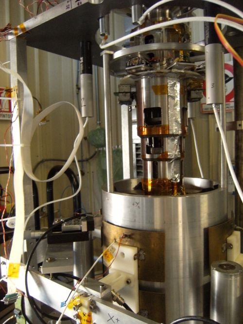
Some news

• GG Phase A-2 Study led by TAS-I in Torino, ASI funded: Drag Free Control & GG
  space experiment simulator based on GOCE expertise of TAS-I Torino team
  (assume VEGA launcher)

• GGG lab & experiment basic funds from INFN-CSNII as a national experiment

•   Additional ASI contribution to GGG: for new vacuum chamber and new
    instrument too improve GGG sensitivity +
•   TAS-I (Torino) to contribute a “GGG Experiment Simulator” also based on
    heritage from GOCE, to be compared with GGG measurement data (“Remote
    Ground Test”)

TAS-I is prepared to complete GG in 4 yrs from start of Phase B for a total
cost of: 69.560 M€ (everything included except the cost of launch with VEGA)

Expression of interest from JPL to participate in GG by contributing to the
payload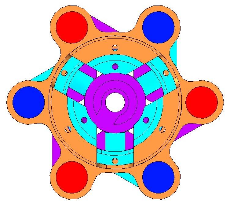
State of the art (I)

                Authors                Apparatus         Source mass     Materials      η ≡ ∆a a
          Eötvös et al. ≈1900     Torsion balance. Not   Earth         Many           10-8 ÷10-9
          collected in Ann.       rotating. No signal                  combinations
          Phys. 1922              modulation
          Roll, Krotkov & Dicke   Torsion balance. Not   Sun           Al − Au        (1.3±1)x10-11
          Ann. Phys. 1964         rotating. 24hr
                                  modulation by Earth
                                  rotation
36 yr
          Braginsky & Panov       Torsion balance.       Sun           Al − Pt        (-0.3 ± 0.9)x10-12
          JETP 1972               8TMs. Not rotating.
                                  24hr modulation by
                                  Earth rotation

                      E. Fischbach et al.: “Reanalysis of the Eötvös Experiment” PRL 1986
  16 yr
          Eöt-Wash, PRD 1994      Rotating torsion                     Be − Cu        (-1.9 ± 2.5)x10-12
                                  balance. ≈ 1hr
                                  modulation             Earth
                                                                       Be − Al        (-0.2 ± 2.8)x10-12

          Eöt-Wash, PRL 1999      Rotating torsion       Sun           Earthlike/     ≈10-12
                                  balance. 1hr to 36’                  Moonlike
                                                                                      (SEP 1.3x10⁻³)
                                  modulation
          Eöt-Wash, PRL 2008      Rotating torsion       Earth         Be − Ti        (0.3 ± 1.8)x10-13
                                  balance.
                                  20’ modulation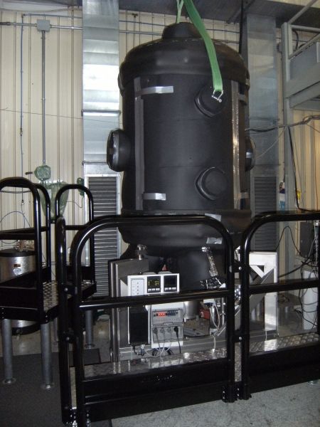
State of the art (II)

      Authors             Apparatus        Source mass   Materials          η ≡ ∆a a
Peters, Chung &
Chu, Nature 1999
                        g measurement with cold atoms (Cs)           10-9

Fray et al with T.   Cold atoms dropping   Earth         85Rb   &    10-7
Hänsch., PRL 2004                                        87Rb

Ongoing
Dimopoulos,          Cold atoms dropping   Earth         85Rb   &    Target: 10-15
Graham, Hogan,                                           87Rb
                                                                     10-16 (10-17)
Kasevich, PRL 2007

                                                    Differ by 2 neutrons only!!!

GGG current sensitivity: 2.3x10⁻⁷ (macroscopic, fast rotating differenetial accelerometer
in the field of the Sun)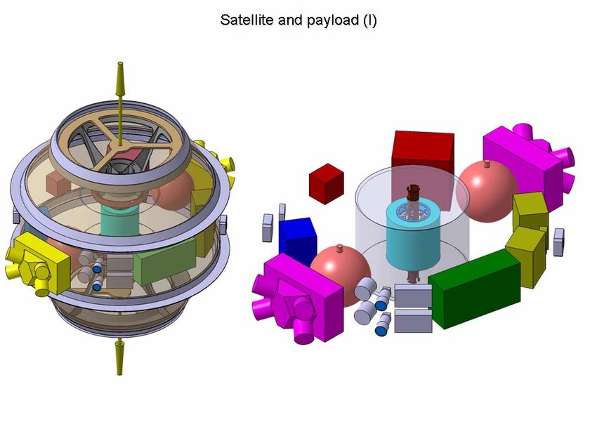
Satellite, orbit and the VEGA launcher
1.6 m
To fly in near circular near equatorial orbit
To be operated from Italian station in Malindi (Kenya)
~600 km altitude
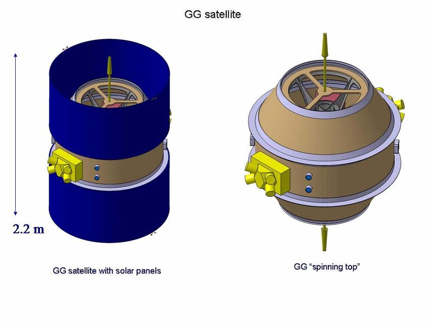
Passive attitude stabilization by 1-axis rotation at 1 Hz 2.2 m
550 kg total mass (with 20% margin) of which ; 100kg launch
adapter, 80 kg payload)
Drag Free Control around orbit frequency
1 yr nominal mission duration (up to 3 yr)
GG satellite in the bay of VEGA
(Kourou launch site)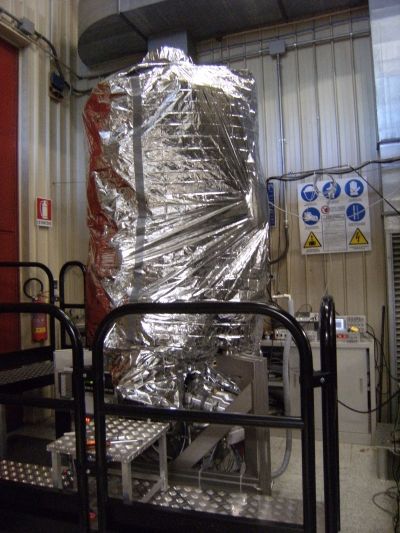
GG differential accelerometer (I)

NOTE: We do not fly a vacuum chamber (use venting to space instead..)
GG differential accelerometer (II)

A second accelerometer has been designed could be accommodated:, same composition test cylinders (for zero
check) CONCENTRIC with the EP violation one... There is only one center of mass of the spacecraft!!
Only the EP accelerometer will fly:
• Once you reach the target sensitivity (TMs relative displacements of 0.5 pm), the signature of an EP violation
  signal in the field of the Earth is well known and so far we have found no perturbation with the same signature
  competing with it to the level of GG target

• TMs material choice to maximize physical chance of violation…
Test masses material choice in GG (I)

Co-rotation makes many disturbing effects DC. Test masses do not need to be manufactured
to very high precision => More freedom in the choice of materials to maximize chance of
EP violation and significance of test

EP violation not expected to depend on macroscopic properties of matter (density,
chemical, mechanical, electric or magnetic characteristics)

Barion number, Lepton number and z component of Isospin (normalized to mass in unit of
the mass of H atom) have been identified (Fischbach & Talmadge, 1998)

                   B/µ                L/µ                 Iz / µ

=> choose test masses materials so as to maximize difference in all 3 these properties!
Test masses material choice in GG (II)
Figure adapted (CH2 added) from : E. Fischbach, C. L. Talmadge: “The Search for Non-
Newtonian Gravity; Springer- Verlag, New York, 1998.Test masses material choice in GG (III) HDPE (High Density Polyethylene) identified – to be tested in GGG (has interesting side consequences.. Not conductive, capacitance read-out possible without capacitance plates in between test cylinders … differential by definition .. )
GG lock/unlock mechanisms

1. Mechanical stops
2. Launch safe lock/unlock (non magnetic actuators)

3. Fine lock/unlock (inch-worm actuators)

                                                                            Designed by DTM
                                                                          Technologies (Ferrari)

                                                                                 “bunny ear” lock/unlock of
                                            Lock/unlock of inner test cylinder                coupling arm
GG EP violation signal recovery EP violation signal after demodulation (from 1Hz rotation)
Drivers and requirements: some numbers (I)
Drivers and requirements: some
          numbers (II)
Drivers and requirements: some numbers (III)
Drivers and requirements: some numbers (IV)
Drivers and requirements: some numbers (V)
Drivers and requirements: some numbers (VI)

                                         …passive MLI sufficient
Drivers and requirements: some numbers (VII) Electric charging & patch effects: • passive electric grounding of the test masses • co-rotation of the test masses and the capacitance transdusers (make patch effects DC or slowly varying if they do slowly vary.. .as they do…) • gold coating • direct measurement of the effects of any patches of charges on test masses, as we have done in GGG (see later..)
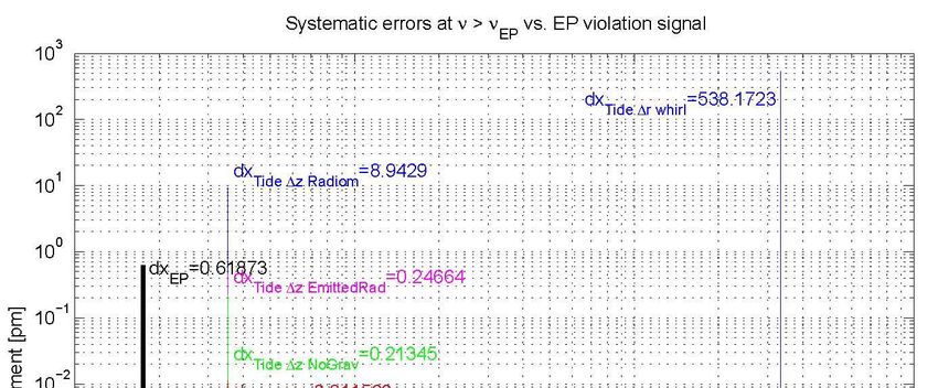
Error budget (I)

How it is built

        Establish requirements

        Implement Drag Free Control
                                                Heritage from GOCE!
        Run GG Simulator

        Analyze time history of test masses relative displacements

        Single out systematic effects and check their magnitude and signature
Error budget (II)
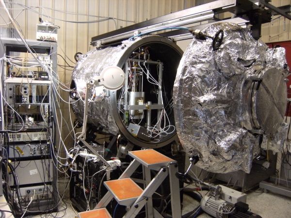
A simulator in the lab: “GG on the Ground (GGG)”

Same number of degrees of freedom; same dynamical properties; position of relative
equilibrium of the test masses in the horizontal plane is NOT stabilized by local gravity (as it
should be as a test of experiment in space…)

GGG lab at INFN Pisa-San Piero a Grado
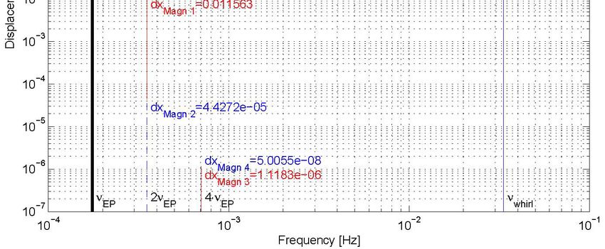
GGG sensitivity: major improvements (I)

FFT of relative displacements of GGG test cylinders in the horizontal, not rotating, plane of lab
GGG sensitivity: major improvements (II)

PSD of relative displacements of GGG test cylinders in the horizontal, not rotating, plane of lab
GGG current sensitivity to EP violation in the field of the Sun

GGG has measured 6x10⁻⁹ m at diurnal frequency with coupling period of 13 s =>
ηsun~2.3x10⁻⁷

                    Limited by terrain tilts: apparatus not suspended, active tilt control only.
                                          Main issue: tilt sensors dependence on temperature
sGGG (suspended GGG) - ASI funds (I)
New chamber
+ new rotor
(under
completion)
New chamber has the right symmetry and has been designed to minimize disturbances on GGG
sGGG will be suspended inside chamber by cardanic joint (not rotating) to reduce low frequency terrain tilts
passively, in addition to active tilt control now in use (Note: active tilt control is limited by thermal effects on tilt
sensor and requires good thermal stabilization to be effective)
An Experiment Simulator will be built by Thales Alenia Space-Italy for the new GGG, similarly to the Simulator
built for the space experiment, to be compared with experimental measurements …sGGG (suspended GGG) – ASI funds (II)
• With the cardanic suspension already manufactured we expect a terrain tilt reduction at low frequencies by
about 5000 (exploit lever effect…)
• With active terrain tilt control (+thermal stabilization) plus passive attenuation we expect to
detect 1 pm displacements (GG target is 0.5 pm) i.e., with current natural test masses
period of 13 s: => ηsun~4x10-11
Longer natural period possible (sensitivity would increasse
quadratically..) but shall we encounter the motor ball bearings
noise???Thermal stability in new chamber Thermal stability of tiltmeter inside chamber (multi stage thermal control): to a few tenths of mdeg down at diurnal frequency (requires 20 mW only)
A better tiltmeter to improve active tilt control?
Double pendulum (one simple + one
inverted, aligned, coupled by tiny
cantilever), based on knife edge
suspensions.
Capacitance transducer with ad hoc
electronic board developed in the lab
based on the AD7745 24 bit capacitance
to digital converter capable to measure
up to 4 picoFarad to a few tenths of
femtoFarad. No additional electronics is
needed outside the vacuum chamber;
data are transferred to the computer
outside via USB port.
Designed to reach 100 s period
(equivalent to a simple pendulum
2500 m long!!!) .. Extremely
sensitive…
On first tests (only rough adjustment of
period and alignment) we have
measured 34.8 s period (equivalent to a
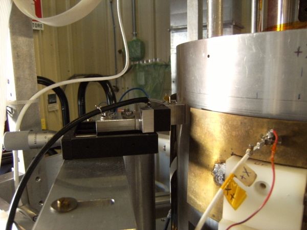
300 m simple pendulum..)Measurement of electric patch effects (I)
Apply a force to the external test cylinder with a
capacitance plate (both grounded)
Since outer and inner test cylinders are coupled, they
will move relative to each other
Their differential motion is measured by the
capacitance bridges (main sensors) located in
between the test cylindersMeasurement of electric patch effects (II)
Q2 Charge changes sign with applied potential, patch
FV =
2ε o S charge does not!
First, apply unipolar potential and measure effect on
TMs; then switch to bipolar potential and measure
effect on TMs (square wave with same period…)
∆x+V 0.75 µ m
∆y+V 0.18 µ mMeasurement of electric patch effects (III)
2Qq
F±V ≡ F patch = q is the charge of patch we want to measure
εoS
displacement ±V q patch V patch by measuring the
=4 =4
displacement +V Q+V V+V displacements in the two
cases we measure Vpatch …
From these
measurements:
∆x±V 0.0275 µ m
V patch 0.3V
∆y±V 0.006 µ m
(Plate made of Al like
test cylinders, no gold
coating…. )Measurement of electric patch effects (III)
• No modeling needed, very neat measurement
• You measure directly the effect of patch charges on the tests masses
• We have done with GGG spinning for 10.6 d, to measure time variation of patch effect
amplitude….
Note: the effect of the patch, in
addition to being brought to the
frequency of the applied potential is
also amplified by the factor:
4Vapplied / V patch
Here it is about 300
⇒ the effect of patch charges (no
coating at all) on GGG test
masses, close to diurnal
frequency is a few picometers
(GG target requires to measure
0.5 picometer)“Galileo Galilei (GG)”
GG undergoing Phase A-2 Study by ASI
(Agenzia Spaziale Italiana) Preliminary (April
2009) Report available on the Web:
http://eotvos.dm.unipi.it/PA2You can also read