120ACU-P39 Enclosure cooling unit - Model - Dindan AC Panel
←
→
Page content transcription
If your browser does not render page correctly, please read the page content below
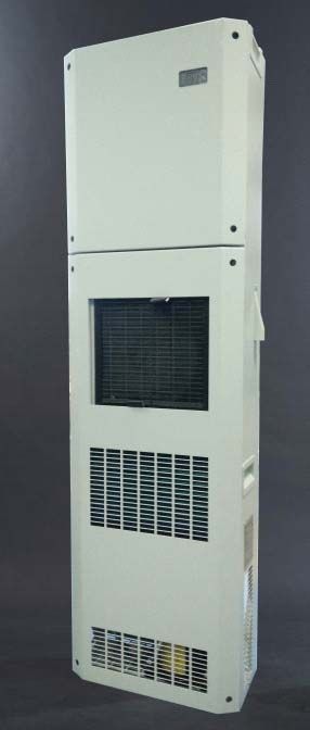
Enclosure cooling unit
       Model
  120ACU-P39
    User's guide

                         ÀÒÉÒä·Â
                         English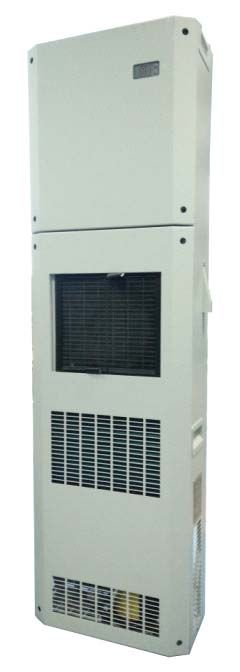
Contents                       Page
1. Over view                    3-5
2. Specification                6-7
3. Notification                  8
4. Technical information        9-10
5. Installation                11-19
6. Maintenance                   20
7. Fault indication              21
8. Assembly and parts number     22

                                       1
Introduction Cooling unit for control cabinet is used for diminishing internal heat by providing cool air to the control cabinet that can protect sensitive equipment It is specially designed to resist surrounding temperature as high as 40-50 oC and can function well in any factories including those with intensive dust, particles and oil mist or with high acidity. 2
1. Over view
               120ACU-P39

                            3
ἧ¤Çº¤ØÁÍسËÀÙÁÔ
(Temperature control board)
¨ÍáÊ´§ÍسËÀÙÁÔ
(Temperature display)
¶Ò´¹éÓ·Ôé§ á¼§·Ó¤ÇÒÁàÂç¹
(Drain pan)
(Evaporator coil)
¾Ñ´ÅÁÊ觤ÇÒÁàÂç¹
(Evaporator fan)
¾Ñ´ÅÁÃкÒ¤ÇÒÁÃé͹
(Condensor fan)
ἧÃкÒ¤ÇÒÁÃé͹
(Condensor coil)
á¼è¹¡Ãͧ½Ø¹è ¤ÍÁà¾ÃÊà«ÍÃì
(Filter) (Compressor)
4HIPROSENT CONTROL (EGS035-1)
B3
B2
B4
B1
CON16 A1 S1
CON20
A2
A3
S2
COM
L 1 2 B C 7 8 5 6 9 10 NO NC Temperature
Display
L
DS1
SR1
OP1
M3
C1
1Ph
M2
220V 50/60Hz
Main connection 1Ph
M1
from 10A BREAKER
supply by Customer 1Ph
Control and Monitor
A1 = LED status
A2 = LED Over/Under Voltage Status
A3 = LED compressor's status
S1 = Temperature setting switch (Up)
S2 = Temperature setting switch (Down)
Cable and signal
B1 = Temperature sensor (inside cabinet)
B2 = Over heat sensor
B3 = Ice sensor
B4 = Ambient temperature sensor
220VAC
M1 = Compressor
M2 = Condenser Fan
M3 = Evaporator Fan
SR1 = Solid State Relay
OP1 = Output Alarm ÁÕ˹éÒÊÑÁ¼ÑÊ NO áÅÐ NC
DS1 = Door Switch (NO = Alarm, NC = Normal)
52. Specifications
Characteristics (under normal operating condition at ambient temp. +35 oC)
Model 120ACU-P39
Capacity Watt 3500
Installation type panel
Input single-phase (V.) 220V+20% / -15%
frequency (Hz.) 50/60
current (35/35) 8.3 (A)
(35/50) 10.5 (A)
Compressor hermetic type rotary
refrigerant type r407c
System operate Direct expand yes
Hi-prosent ctrl1. thermostat yes
condensor thermal detector yes
anti-freeze detector yes
compressor overheat detector yes
water detector none
Protection over drain protect system yes
Display thermometer (red 7 segment 19 mm.) yes
system status (2 colour LED) yes
Electrical equip. safety device 12A. slow-blow fuse
Evaporator coil face area x rows 97.5 sq.inch x 5
blower fan(r.p.m.) 1440
number of blower fan x cfm 1 x 360
Condenser coil face area x rows 143.5 sq.inch x 7
centrifugal fan (r.p.m.) 2750
number of centrifugal fan x cfm 1 x 1530
Physical data approx.weight (kgs.) 90
dimension (mm.) W:465 D:270 H:1600
condensate drain OD. 1/2 inch
internal casing electro-galvanize
Air filter width x lenth (mm.) 305 x 285
6465
85.5 90 90 90 85.5 12
12
100
RETURN AIR TO
142 AIR CONDITIONER 100
66 316 100
165
100
67 COLD AIR OUT
130 214 100
100
Installation Plate & Templet for cutting Area
100
View From Outside of Cabinet Drill 3.2 mm.
1595
100
100
Cutting & Drilling Templet
This dimension is viewed
1155 from outside Cabinet 100
100
Cut for SocketPlug
100
100
TOP VIEW 85 100
465
100
190
DIMENSION in mm.
270
45 105 15
FRONT VIEW SIDE VIEW REAR VIEW
Return Air In
Cold Air Out
Air Filter Pocket
1600
Ambient Air In
Warm Air Out
Warm Air Out Warm Air Out
73. Notification
Before, drilling, and cut. should use clean dry cloth, or the inventory doesn’t
lead the electricity, covers the equipment for protects iron dust touches the
electrical equipment while installing. (In case of machine still operate.)
Cooling unit should be installed in the good circuration area
Check vertical
o
and horizontal level of which their error shall be allowable
within +/- 2 in order to facililate efficient drainage
Should always install gasket between Installation plate and Cooling Unit
before hang the cooling unit on the installation plate
Installing of drain tube (Page 17)
In order to minimize water condensation, cabinet doors should be tightly closed
during operation
Circulation fan should be installed in cabinet if various equipment is densely
installed inside
In order to obtain highest performance and durablility, repair and alteration of
cooling unit should be under care of distributor
o
Should not adjust temperature difference more than 10 C betwee
enviromental temperature and cooling space, to prevent moisture build up on
some part in the cooling area when you open the cabinet panel
If it is necessary to set temperature lower than 25oC, it is recommended to
use precision cooling unit or contact your Professional Maker.
The equipments that are locate in the cooling air stream have to be
obstructed by the insulator to prevent water condensation
8General Condition
Storage: Cooling unit should be stored at temp not exceeding 70 oC
Transportation: This type of cooling unit can't be laid down horizontally.
Installation: It shall be installed in vertical direction only
(please see figure below)
CORRECT INCORRECT
Disposal of damaged Cooling Unit
As its refrigeration system contain Refrigerant and lubricating oil for
compressor, in order to protect environment, these substances should be
disposed of properly or other under direction given by distributor.
4. Technical information
Protective equipment
Refrigeration system has been tested with high pressure device at 350 PSI.
This series of cooling unit also contains electronic circuit and sensors are
installed at significant points to monitor any defect of refrigeration cycle in order
to reduce burden of the user and to prolong use life of cooling unit at more
costeffective practice.
Note
- LED light will display green colour (continuously) to indicate condition.
- Under any abnormal condition, please see pages 21.
9Refrigeration Cycle
Condenser
Filter
Compressor dryer
External
Internal
Cap.tube
Evaporator
Drainage
Drainage of condensed water from cooling system shall be done by inserting
drain tube under drainpan (see page 17) and trying not to left it twisted. Make
sure, the other end of drain tube is not lower than water level in the container,
in order to avoid water reflux
Drain tube Drain tube Drain tube
Correct installation Incorrect installation
105. Installation
Accessories for 120ACU-P39
Parts Quantity
Cooling unit 1
User's guide & Warranty card 1
Socket plug guard 1
Socket plug 1
Special holder (see page15) 2
Upper gasket 1
Lower gasket 1
Air filter 1
Installation plate 1
Self tapping screw 1/8'' x 1/2'' (for socket plug) 4
Self tapping screw 1/8'' x 3/8'' (for Installation plate) 48
1/2'' drain tube (200 cm.) 1
3x4.0 Sq.mm. power cord (300 cm.) 1
Spring washer (for M10 x 45 mm. bolt) 4
M10 x 45 mm. bolt 4
3/4'' Cable clamp 3
6'' Cable tie 10
11Installation procedures
Note: please read page 8, item 3 before install cooling unit
1. Align Installation plate in the position and water level check
(see figure below)
2. Lay out No.1-39
17 18 19 20
16 21
37 15 RETURN AIR TO
AIR CONDITIONER
22
14 23
13 24
38 25
12 COLD AIR OUT
11 26
10 27
9 28
8 Installation 29
plate
7 30
6 31
5 32
4 33
105
3 34
39 85
2 35
1 36
123. Cover equipment in cabinet with clean dry cloth, or the inventory doesn’t lead
the electricity, and cover with paper box at position will be drilling and cutting in
order to prevent metal scrapt falling in cabinet. (see figure below)
Paper box
4. Drilling the layout position in item 2 page 12 by following these following steps:
4.1 Drill 1 - 36 by applying drill bit size 1/8'' (3.2mm.)
135. cutting the layout position in item 2 page 12 by following these following steps:
5.1 Cutting for air return at 37, dimension 316x142 mm.
5.2 Cutting for air outlet at 38, dimension 214x67 mm.
5.3 Cutting for socket plug at 39, dimension 105x85 mm.
6. File the cutting edge and paint rust proof colour
File
147. Installation plate attachment
7.1 Screw 36 self tapping screws (1/8" x 3/8")
7.2 Fasten Special holders (included with installation accessories)
Special holders
M10 bolt &
Stainless Sheath
8. Gaskets installation
8.1 Peel of tape covers on the 2 gaskets double side tape
8.2 Stick these gaskets on the positions (Gaskets will be installed
between installation plate and cooling unit)
Special holders
upper gasket
lower gasket
Socket Plug
159. Hang the cooling unit on the installing plate (see figure below)
10.Fasten M10x45 mm. bolt (4 unit)
4x Bolts M10 mm.
I
NL
DU
1611. Drainage system (This cooling unit has both side drain outlets.) Drain tube of
any side can be used (see figure below). Under drain pan has 2 drain outlets
on both side either which shall be pluged when the other side is under use.
Likewise, drain outlet is split to both sides one of which has to be closed (by
the metal sheet) provided when another one is under use while B36-1 is to be
taken off and flipped over to fasten from the outside covering drain tube for
tiding before use.
Figure demonstrating installation of drain tube
B36-1-1
Rubber plug
B36-1
I
NL
DU
Drain tube handle
Drain tube OD 1/2"
Container
Magnified figure of insertion of B36-1
1 No.1 Plug unused tube with rubber plug
5 N0.2 Apply B36-1 (drain tube cover)
N0.3 Fasten self tapping screw to B36-1
2 3 N0.4 Connect drain tube to drain pan 5
4
Caution : Avoid immerse drain tube under water level (see page 10)
1712 Connecting electrical power supply to cooling unit
12.1 Install socket plug (included with installation accessories)
12.2 Install socket plug guard behind socket plug (included in installation
accessories)
12.3 Connect the power cord to the socket plug
12.4 Install 2x4.0 sq.mm. cable between power source (25A Breaker)
to socket plug (for supply 220Vac to socket plug)
I
NL
DU
Socket plug guard
Socket plug install from the back
Caution : 25Amp. breaker of cooling unit should not be supplied to other
equipments
13.Close all of the panels of cooling unit
14.Turn on breaker to supply power for cooling unit
18Air diverter installation (In the necessary case)
1. single air diverter
Turn the air diverter to blow air down as shown below the drill and fix it.
Diverter
2. Multiple air diverters
Turn air diverters to blow air down as shown below the drill and fix it
Diverters
Note Air diverter is the additional, not appropriate with common installation
equipment.
196. Maintenance
Maintenance of DINDAN cooling unit can be simply done by giving care to the air
filter and condensor coil not to be clogged up. The cleaning interval for the air filter
depends on how dirty it is of the area where it is installed.
In case of abnormal function, it can be noticed from LED light which is to change
in corresponding with abnormal condition of cooling unit. For more details please
see page 21.
Direction
It is suggested to scrape condensor and evaporator coil at least once a year.
Condensor coil scraping is a cleaning method that can effectively save power con-
sumption and a significant factory for prolonging compressor's use life. Method for
condensor scraping (please see page 22) can be started from taking off part No.7
and then scrapping dirt collected on condensor coil.
207. Fault indication and analysis:
21
LED A / display Nature of fault Cause Remedy Unit's operation
Green / temperature - - - normal
Green / E01* Over voltage High voltage supply (264V.)** Check line voltage connection and Automatically shut off
(LED B = Red) Supply new line power
Green / E02* Under voltage Under voltage supply (187V.)** Check line voltage connection and Automatically shut off
(LED B = Red) Supply new line power
Green / E03 Over current Defective equipment Carry out of cooling service Automatically shut off
Red & Green Flood of water Obstruction in condensate drain Clean or replace drain hose Automatically shut off
alternately blink / E04*** Unit is not fitted vertically Adjust the enclosure level carefully
Green / E05 Door Switch Control cabinet doors open Close the control cabinet door Automatically shut off
Red color blink / E06 Risk of icing Operational indication, icing up Raise the set point value of the internal temperature Automatically shut off
Evaporator contaminated Clean
Evaporator fan defective Replace
Lack of coolant Carry out of cooling service
Red / E07 Hi-pressure in Ambient temperature too high Unit's specified range of application exceed The unit still operate
refrigerant system Condenser contaminated Clean
Filter mat contaminated Clean or replace
Condenser fan defective Replace
Red / E08 Alarm E07 more than 4 hr.(Ref Red / E07) (Ref Red / E07) Automatically shut off
No signal Unit not operate Control panel switch off Switch on the control panel Unit not operate
No voltage supply Supply new line power
Internal fuse has broken Carry out of cooling service
Note * If the return voltage is normal.The cooling unit will run again automatically
** Hight Voltage cut-out/cut-in = 264/253 V. , Under Voltage cut-out/cut-in = 187/195 V.
*** Top model only (rooftype installation model)
LED A = LED Status
LED B = LED Over/Under Voltage
LED C = LED Cooling (Compressor Status)8. Spare part
5 4
6
3
7
1 2
ITEM DESCRIPTION PART NUMBER
1 compressor EP-04-D01
2 condenser Coil CR-09-D02
3 centrifugal fan EP-03-D02
4 evaporator Coil CR-08-D02
5 control board XEE-22-016
6 blower with housing EP-03-615
7 filter CR-15-603
22You can also read