Manual Curtain Sensors - Model
←
→
Page content transcription
If your browser does not render page correctly, please read the page content below
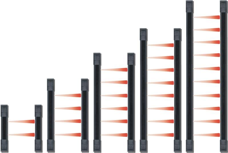
Curtain Sensors
                          Manual

Model          Number of Beams     Length   Color
E-9680-10B25         10              80”    Black
E-9660-8B25           8              60”    Black
E-9644-6B25           6              44”    Black
E-9644-6W25           6              44”    White
E-9622-4B25           4              22”    Black
E-9622-4W25           4              22”    White
E-9611-2B25           2              11”    Black
E-9611-2W25           2              11”    White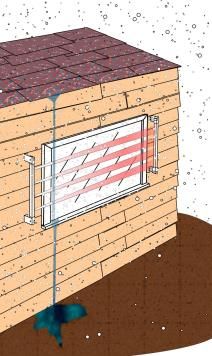
ENFORCER Curtain Sensors
Table of Contents:
Features ....................................................... 2 Running the Wires ........................................ 5
Parts List ....................................................... 2 Connecting the Wires................................ 5~6
Dimensions ................................................... 2 Removing the Lens Caps .............................. 6
Specifications ............................................... 2 Connecting One or More Sensors ................ 7
Sample Installations ..................................... 3 Mounting the Transmitter and Receiver and
Choosing a Location ................................. 3~4 Testing the Sensor .................................... 7
Selectable 3-Channel Beam Frequency ....... 4 Tamper Protection ........................................ 8
Mounting the Curtain Sensor .................... 4~5 Troubleshooting ............................................ 8
Features:
Multi-frequency to reduce interference 2, 4, 6, 8, or 10 separate photoelectric beam
f between multiple units sensors; programmable trigger upon
Install on windows, doorways, skylights, breaking of any single beam or simultaneous
fence tops, and any place where space is breaking of any two adjacent beams
limited Anti-tamper circuit for use when power is cut
Perfect for indoor and outdoor perimeter or end cap is removed
security No synchronizing wires required
Slimline design – 15/16”x7/8” (33x22 mm) LED alignment indicator
Rugged aluminum construction L-brackets and mounting hardware included
NO/NC Relay output
Parts List: Dimensions:
Top View
1x Transmitter
1x Receiver
17/32” (30.6mm)
15/16” (33.5mm)
4x L-Brackets 11.25” (29cm) – E-9611-2x25 60.1” (153cm) – E-9660-8B25
1x Manual 22.5” (57cm) – E-9622-4x25 79” (201cm) – E-9680-10B25
44.5” (113cm) – E-9644-6x25
Mounting hardware
Side View
7/ ” (22.3mm)
8
3/ ” (19.6mm)
4
Specifications:
Model E-9611-2x25 E-9622-4x25 E-9644-6x25 E-9660-8B25 E-9680-10B25
Standby@12~24 VDC 80mA 89mA 94mA 102mA 110mA
Active@12~24 VDC 60mA 73mA 79mA 92mA 100mA
111/4”x15/16”x7/8” 221/2”x15/16”x7/8” 441/2”x15/16”x7/8” 601/8”x15/16”x7/8” 79”x15/16”x7/8”
Dimensions
(286x33x22 mm) (572x33x22 mm) (1130x33x22 mm) (1527x33x22 mm) (2007x33x22 mm)
Response time 0.5~20 ms 0.5~32.5 ms 0.5~48.5 ms 0.5~60 ms 0.5~70 ms
Maximum range Indoor: 50’ (16m), outdoor: 25’ (8m)
Detection method Simultaneous break of 2 adjacent beams or any single beam (programmable)
Output NO/NC Relay output, 1A@12~24 VDC
Operating temperature -49°~131° F (-45°~55° C)
Attenuation LED ON: Powered, aligned properly; Flashing: Beam broken or unaligned; OFF: No power
Enclosure / Case IP65 / Aluminum alloy
2 SECO-LARM U.S.A., Inc.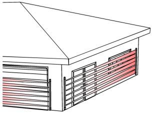
ENFORCER Curtain Sensors
Sample Installations:
Typical Door/Window Windows Indoor Fence Tops
Frame
Garages/Gates/Walls Skylights
Important:
Do not connect to power until the sensor is completely installed and the installation has been
double-checked.
Choosing a Location:
When used outdoors, place the curtain sensor under a roof or shelter. This will reduce the
chance of false alarms caused by rain or snow.
To prevent erratic operation and/or false alarms:
Wind will not directly cause false alarms, but
Fig. 1: Beware Natural Interference
could cause leaves or similar objects to fly
into or otherwise obstruct the beams. Do
not mount near trees, bushes, or other leafy
vegetation (see Fig. 1).
Do not mount where water running off the
roof might break the beam (see Fig. 1). The
sensor and beams must be sheltered. Tree or shrub leaves
Do not mount near reflective surfaces, as this
could prevent the sensor from working Rain running directly
properly. off roof thru beams
SECO-LARM U.S.A., Inc. 3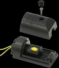
ENFORCER Curtain Sensors
Choosing a Location, continued:
Do not mount where the transmitter or
receiver could be splashed by water or Fig. 2: Orientation to Sun
mud. NO
Do not mount where unit could be
suddenly exposed to a bright light, OK*
such as a floodlight or a passing car’s
headlight.
Do not let sunlight or any direct beam of TX RX
light shine directly on the curtain beam *Only if unavoidable. Mount so
sensor. If unavoidable, mount so the transmitter, not receiver, faces RX TX
the sun.
transmitter, not the receiver, faces the
sun (see Fig. 2).
Do not mount where animals or other objects could accidentally break the beams.
Selectable 3-Channel Beam Frequency:
The sensor beam frequency can be set at different
frequencies on-site to avoid interference from multiple
Fig. 3: JMP3
curtain sensors nearby. To select between three different Jumper Frequency A
beam frequencies, set the jumper of the transmitter side Position Frequency B
and receiver side (see Fig. 3).
Frequency C
Note:
1. If the frequency is changed, power must be cycled on the transmitter and receiver
after the new frequency is selected.
2. Both the transmitter and the receiver of each pair must be set to matching
frequencies to work together correctly.
Mounting the Curtain Sensor:
1. Find a suitable location (see Fig. 1):
a. The transmitter and receiver can be
Fig. 4: Orientation Terminal
block
mounted at any angle as long as they are Note: If the wires will
parallel to each other and directly facing be running out the end,
each other, and as long as the wires place sensors so wires
come out of the same ends of both units are at the bottom. If
(see Fig. 4). sensors must be placed
OK so wires are at top, NO
b. If using multiple curtain sensors, be sure
seal the opening with
to set each for a different frequency (see
silicone to prevent
Selectable 3-Channel Beam Frequency
water from leaking in.
above).
{
Terminal
c. The transmitter and receiver must not be blocks
separated by more than 50 feet indoors Terminal
block
and 25 feet outdoors.
4 SECO-LARM U.S.A., Inc.
ENFORCER Curtain Sensors
Mounting the Curtain Sensor, continued:
                                                               Fig. 5:    Plastic cap
2. Mount the transmitter and the receiver so that the        End       hiding screw
   surface-mounted wires do not come out from above                                 Screw
                                                             Cap
   the units. This is to prevent water from entering via     Cover
   the wire holes. If this is unavoidable, use silicone to
   completely cover the area where the wires come out
   the holes to prevent water from entering (see Fig. 4).                           Tamper Button
3. Once a suitable mounting location has been found,
   remove the covers of the end caps (see Fig. 5), and
   pull the tamper buttons out of the end caps (one per
   transmitter or receiver) and locate the mounting holes.
   Using these holes as a template, mark their location on the wall with a pencil.
4. Connect the wires (see Figs. 6 and 7) before permanently mounting the units to the wall.

Running the Wires:
Run four wires (2x power and 2x alarm signal) from          Table 1: Maximum Wire Length
the alarm control panel to the receiver of the curtain      Voltage      Gauge          Max. length
sensor. Shielded cable is strongly suggested. See           12VDC        AWG 22         1800’ (550m)
                                                            12VDC        AWG 20         2600’ (800m)
Table 1 to the right for maximum wire length. Two
                                                            24VDC        AWG 22         2600’ (800m)
power wires must also be run to the transmitter.            24VDC        AWG 20         3900’ (1200m)
It may be more convenient to connect the transmitter’s two power wires to the receiver’s power
wires. In this case, run six wires to the receiver: two wires to the power source, two for the alarm
signal, and two to the transmitter.
Note:
     1.   If burying the wires is required, make sure to run them through electrical conduit.
          Shielded cable is strongly suggested.
     2.   If the wires are run along the wall, using an armored cable is strongly suggested.

Connecting the Wires:
1. Receiver:                                           Fig. 6:
   a. Pull the end cap with the red wire leads off the Wiring the
      receiver, and slide the PCB out far enough to    Receiver
                                                                                                 COM
                                                                                                 N.C.
                                                                                          N.O.

      expose the wiring block.
                                                                                          }

   b. Run the four wires (or six wires, if connecting          To Alarm      To Alarm Control Panel
      the transmitter’s power wires to the receiver)           Control Panel COM + N.O. or
      through one or more of the three ground                  12~24 VDC     COM + N.C.
      knockout holes in the end cap near where the
      tamper button wires run, and connect them to     Fig. 7: Wiring
      the wiring block (see Fig. 6).                   the Transmitter
   c. Program the receiver (see Table 2 on pg. 6).
                                                                               To Alarm Control Panel
   d. Carefully push the PCB back into the case                                12~24 VDC
      and reinsert the end cap.
   e. Reinsert the cap over the tamper button and small tamper cap.
SECO-LARM U.S.A., Inc.                                                                                  5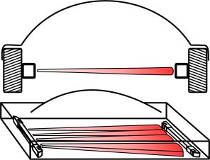
ENFORCER Curtain Sensors
Connecting the Wires, continued:
2. Transmitter:
a. Pull the end cap with the red wire leads off the transmitter, and slide the PCB out far
enough to expose the wiring block.
b. Run the two power wires through one or more of the three round knockout holes in the end
cap near where the tamper button wires run; connect them to the wiring block (see Fig. 7).
c. Program the transmitter (see Table 2 below).
d. Carefully push the PCB back into the case and reinsert the end cap.
e. Reinsert the cap over the tamper button and small tamper cap.
Note:
1. Screw the wires tightly to avoid slipping off the terminals, but not so tight that they break.
2. Unused terminal screws should be tightened.
3. Grounding may be necessary, depending on the location.
Table 2: Transmitter and Receiver Programming
Receiver Transmitter
Jumper name JMP1 JMP0
LED Operation 1 C 2 1 C 2 LED ON LED OFF
LED ON if power is LED OFF if power is LED ON if power LED OFF at
present and beams present and beams is present. all times.
are aligned. are aligned.
LED flashes when LED flashes when
beams are broken. beams are broken.
Jumper name JMP2 SA1
Number of beams
1 Beam 2 Beams 1 Beam 2 Beams
to interrupt to
trigger transmitter
Receiver triggers if Receiver triggers Transmitter Transmitter triggers
and receiver
any single beam is only if 2 adjacent triggers if any only if 2 adjacent
interrupted.* beams interrupted single beam is beams interrupted at
at same time.* interrupted.* same time.*
*Both JMP2 and SA1 should be taken off or left on at the same time.
Removing the Lens Caps (for outdoor use only):
For best results when the curtain sensor is mounted outdoors, remove the transmitter lens caps
(DO NOT remove the receiver lens caps!).
Fig. 8: Removing the Lens Caps
To remove the lens caps (see Fig. 8):
1. Slide the PCB out of the transmitter (see
“Connecting the Wires” on pg. 5~6).
2. Carefully pull the lens cap off of all the lenses
(4 for the E-9611-2x25, 8 for the E-9622-4x25,
12 for the E-9644-6x25, 16 for the E-9660-8B25, 20 for the E-9680-10B25).
3. Slide the PCB back in (see “Connecting the Wires” on pg. 5~6).
6 SECO-LARM U.S.A., Inc.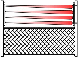
ENFORCER Curtain Sensors
Connecting One or More Sensors:
Several units can be connected together in parallel to the same power supply output and alarm
input of an alarm control panel.
Please reference Fig. 6 & 7 for terminal blocks.
Standard
                                                                              } Power
                                                                              } Alarm signal

                                                                             Control panel
      Transmitter                 Receiver                                     (12VDC)

Dual Sensors, Separate Alarm Channels
                                                                              } Power
                                                                              } Alarm (ch. 1)
                                                                              } Alarm (ch. 2)

                                                                             Control panel
                                                                               (12VDC)
      Transmitter                 Receiver    Transmitter    Receiver

In-line, Single Alarm Channel
                                                                              } Power
                                                                              } Alarm signal

                                                                             Control panel
       Transmitter                 Receiver   Transmitter     Receiver         (12VDC)

Mounting the Transmitter and Receiver and Testing the Sensor:
1. Temporarily mount the transmitter and receiver to where they are expected to be mounted, so
   the mounting position can be changed if necessary.
2. Connect the transmitter and the receiver.
3. Once it is powered up, test the curtain sensor by breaking two adjacent beams or any single
   beam (depending on programming).
4. The curtain sensor also has red LEDs which can be used for testing purposes (see Table 2).
5. After the curtain sensor is tested and aligned, permanently mount it.
6. After it is mounted, test the curtain sensor again.

SECO-LARM U.S.A., Inc.                                                                           7
ENFORCER Curtain Sensors
Tamper Protection:
The receiver and the transmitter both have a tamper switch on one end to protect against someone
attempting to open the unit. However, there is no separate tamper output to the alarm control
panel. Instead, the alarm output is triggered if the cover of the end cap with the tamper button is
removed, if the transmitter or receiver is moved out of alignment, or if power is disconnected.
Troubleshooting:
Test the power and ground wire with a voltage meter to
Transmitter LED will not turn ensure power is connected and is of the correct voltage.
ON Change the position of the transmitter jumper “JMP0”
(see page 6).
Test the power and ground wire with a voltage meter to
Receiver LED will not turn ON
ensure power is connected and is of the correct voltage.
Receiver LED will not turn ON Change the position of the receiver jumper “JMP1”
unless the sensor is triggered (see page 6).
Receiver LED flashes
Check that the transmitter and receiver are aligned.
continuously
Does not trigger when beam is Remount the curtain sensor away from any shiny surface,
broken or repaint the surface to cut down on reflection.
Check that the transmitter and receiver are aligned.
Receiver continuously triggers
Check that the tamper button and the cover for the
the alarm
tamper button are mounted correctly.
Re-install so that multiple sensors do not interfere with
each other.
False alarm Cut back leafy vegetation.
Re-mount away from the edge of a roof.
Mount under a roof or shelter.
LIMITED WARRANTY: This SECO-LARM product is warranted against defects in material and workmanship while
used in normal service for one (1) year from the date of sale to the original customer. SECO-LARM’s obligation is limited to
the repair or replacement of any defective part if the unit is returned, transportation prepaid, to SECO-LARM. This Warranty
is void if damage is caused by or attributed to acts of God, physical or electrical misuse or abuse, neglect, repair or
alteration, improper or abnormal usage, or faulty installation, or if for any other reason SECO-LARM determines that such
equipment is not operating properly as a result of causes other than defects in material and workmanship. The sole
obligation of SECO-LARM and the purchaser’s exclusive remedy, shall be limited to the replacement or repair only, at
SECO-LARM’s option. In no event shall SECO-LARM be liable for any special, collateral, incidental, or consequential
personal or property damage of any kind to the purchaser or anyone else.
NOTICE: The information and specifications printed in this manual are current at the time of publication. However, the
SECO-LARM policy is one of continual development and improvement. For this reason, SECO-LARM reserves the right to
change specifications without notice. SECO-LARM is also not responsible for misprints or typographical errors. Trademarks
are the property of SECO-LARM U.S.A., Inc. or their respective owners.
Copyright © 2014 SECO-LARM U.S.A., Inc. All rights reserved. This material may not be reproduced or copied, in whole or
in part, without the written permission of SECO-LARM.
SECO-LARM® U.S.A., Inc.
16842 Millikan Avenue, Irvine, CA 92606 Website: www.seco-larm.com PICTN1
Phone: (949) 261-2999 | (800) 662-0800 Email: sales@seco-larm.com MiE-96xx-xxB25_141008.docx
8 SECO-LARM U.S.A., Inc.You can also read