Stab resistance of bulletproof vests. A conceptual model of test bench
←
→
Page content transcription
If your browser does not render page correctly, please read the page content below
MATEC Web of Conferences 317, 06002 (2020) https://doi.org/10.1051/matecconf/202031706002
Power Transmissions 2020
Stab resistance of bulletproof vests. A conceptual model of test
bench
Svetlana Yaneva
Technical University of Sofia, Faculty of Mechanical Engineering, Department of Fundamentals and Technical Means of Design,
Bulgaria
Abstract. This paper presents a conceptual model of a stand to test the physico-mechanical characteristics
of materials used in the soft panels of bulletproof vests for their stab resistance to cold weapons having a
sharpened blade portion firmly and rigidly attached to handle. In the process of conceptual design of the
model, the requirements and norms set out in two of the leading standardization documents used to
determine the stab resistance of the bulletproof vests: the standard of the US National Institute of Justice -
NIJ 0115.00, Stab Resistance of Personal Body Armor, and the UK Police Standard - HOSDB 2007. Part 3 -
Knife and Spike Resistance, have been taken into account. 3D models of the stand and its individual
constructive elements were developed, on the basis of which were offered real elements and devices for its
elaboration. The designed stand is technologically accessible, inexpensive and easy to manufacture and
install. It can be used to pre-determine the stab resistance of different types of materials and their
combinations used in the soft panels of the bulletproof vests in the process of improving their structure.
Availability of such stands in the equipment of the producers laboratories involved in this type of activity
would reduce costs and shorten the evaluation time of the tested materials in order to verify their
compliance with standard requirements since only samples showing the highest stab resistance will have to
be sent for testing in certified and accredited laboratories.
1 Introduction requirements of any of the applicable standards in the
field [3-5].
Nowadays, the issue of the security of law enforcement, In this report is presented a conceptual model of a
such as anti-terrorism, police and security guards, is stand to test the physico-mechanical characteristics of
extremely up-to-date. Of great importance for the materials used in the soft armor of a bulletproof vest for
protection of their health and life during the performance their stab resistance by a cold weapon having a
of their official duties are the personal protective sharpened blade portionmour firmly and rigidly attached
equipment to which the bulletproof vests belong. to handle.
The design and protective features of modern
bulletproof vests are continually being refined to meet
the wide range of weapons and ammunition used. In 2 Basic requirements for the developed
addition to ballistic protection from a wide range of stand
bullets and splinters, they also need to provide adequate
protection against stabbing with a cool weapon, which is In the process of conceptual design of the model the
of great importance in close contact with an attacker. An requirements and norms set out in two of the leading
important role in this respect is the materials that make standardization documents used to determine the
up the soft panel of the bulletproof vest [1, 2]. They need durability of the bulletproof vests: the standard of the US
to be thoroughly studied, analyzed and carefully National Institute of Justice - NIJ 0115.00, Stab
combined. Resistance of Personal Body Armor [3] and the UK
In the process of refinement of the soft panels, the Police Standard - HOSDB 2007. Part 3 - Knife and
various combinations of materials used to construct their Spike Resistance [4], have been taken into account. The
structure should be subjected to a series of tests, following additional requirements to which the model of
depending on the desired level of protection, in order to test bench must respond, have been formulated:
establish their protective properties and suitability for technologically accessible, easy to manufacture and
use. They must guarantee high security values and full install;
protection for all vital organs, subject to strict weight modular construction type;
limitations for the bulletproof vest and meet the mobile and repairable construction;
high accuracy of tests;
*
Corresponding author: svetlana_ianeva@tu-sofia.bg
© The Authors, published by EDP Sciences. This is an open access article distributed under the terms of the Creative Commons Attribution
License 4.0 (http://creativecommons.org/licenses/by/4.0/).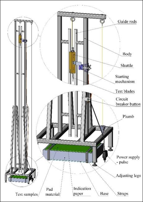
MATEC Web of Conferences 317, 06002 (2020) https://doi.org/10.1051/matecconf/202031706002
Power Transmissions 2020
optimal price;
the free fall of the puncture blade under the action of
its own weight;
stand height, providing the necessary energy for
testing at all levels of protection;
possibility of adjusting the angle of encounter of the
test blade with the test sample against the normal at
0°, 15°, 30° and 45°;
the possibility of conducting tests according to the
methodologies of the aforementioned
standardization documents.
The test stand is designed to work in laboratory
conditions to pre-determine the resistance to puncture of
different types of materials and their combinations used
in soft armor panels in the process of refinement of their
structure.
The 3D models of the stand and the individual
elements of its construction have been developed using
SolidWorks [6].
3 Main components and the principle of
the action of the stand
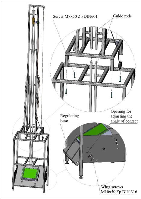
The construction of the stand is built on a modular
principle and includes a basic module (Fig.1) and an
additional module (Fig.2):
Fig. 2. Design of the stand, additional module (3D model S.
Yaneva).
3.1 Basic module
The basic module is used to test for resistance to
puncture of soft ballistic bulletproof panels for the first
and second protection levels according to NIJ 0115.00,
at the test blade angle with the test specimen 0° relative
to the normal one. It consists of:
3.1.1 Body
Welded construction of steel tube profiles, powder
coated, to which the following components are mounted:
3.1.2 Guide rods
Pipe sections with circular cross section, made of
stainless steel whose function is to ensure a vertical drop
of the shuttle carrying the test blade in the friction stand
construction tending to zero.
3.1.3 Shuttle
This is the device (Fig. 3) with a precise mass (1900g ±
15g), consisting of a body (pos.1) of a specific shape
made of brass alloy at the lower end, whereby by means
of screws (pos.2) attach the test blade (pos.3). In the
middle part of the brass body, a plate (pos.5) is fastened
Fig. 1. Design of the stand, basic module (3D model S. by means of two screws (pos.4) to fix the shuttle to the
Yaneva). trigger mechanism. A screw (pos.6) is attached to the
upper part of the body with calibrated weights (pos.7)
2
MATEC Web of Conferences 317, 06002 (2020)                                            https://doi.org/10.1051/matecconf/202031706002
Power Transmissions 2020

  serving to adjust the mass of the shuttle, which are fixed         3.1.4 Starting mechanism (Fig. 6)
  with a nut (pos.8). A textile cord is attached to the screw
  (pos.6) to bring the shuttle to its starting position after        It consists of an electromagnet pulling (real element) and
  impact on the test specimen. The shuttle moves in the              a stand, which makes it possible to easily move the
  guides whose function is to ensure that the test blade             trigger mechanism to the required test height by means
  (vertical) drops freely in the construction of the stand,          of nut screws.
  with a friction that is tilted to zero. It falls freely at a
  specific height (so as to provide the required impact
  energy for the given level of protection) under its own
  weight while the test blade attached to it strikes the front
  of the test specimen with a certain force. The shuttle is
  designed such that, when the test blade is attached, it is
  83 mm ± 2 mm away from it. The shape of the lower
  surface of the falling body allows for a minimum of 30
  mm penetration at the impact of the bulletproof vest at a
  45 ° angle from the normal.

                                                                     Fig. 6. Starting mechanism - open frame solenoid (3D model S.
                                                                     Yaneva).

                                                                     3.1.5 Circuit breaker button
                                                                     Used to set into motion the trigger mechanism by
                                                                     manually turning on the electric circuit. The button
                                                                     switch (Fig. 7) is made of a contact system, a body and a
                                                                     button.

  Fig. 3. Shuttle (3D model S. Yaneva).

     In Fig. 4 shows the structure of the device carrying
  the test blade according to NIJ 0115.00, called "Drop              Fig. 7. Circuit breaker button (3D model S. Yaneva).
  mass". In Fig. 5 shows the device carrying the test blade,
  used in tests on HOSDB 2007. Part 3, called "Missile".
                                                                     3.1.6 Power supply - pulse
                                                                     Provides the required power to operate the trigger
                                                                     mechanism. A Wall Mount Power Adapter (Fig. 8) is
                                                                     selected, an input voltage of 90 ÷ 264VAC; output
                                                                     voltage 24VDC; output current 0.5A; maximum power
                                                                     12W; CP> 77,80%; operating temperature 0° C ~ + 40°
  Fig. 4. Drop mass (NIJ 0115.00) [3]                                C; sizes 63x45x29mm.

  Fig. 5. Missile (HOSDB 2007. Part 3) [4].                          Fig. 8. Power supply – pulse (3D model S. Yaneva).

                                                                 3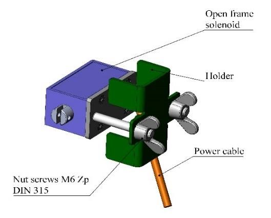
MATEC Web of Conferences 317, 06002 (2020)                                             https://doi.org/10.1051/matecconf/202031706002
Power Transmissions 2020

   3.1.7 Plumb                                                            In Fig. 10 shows the 3D model of the entire
                                                                       construction of the developed stand (basic + additional
   A massive steel body with conical shape to which a                  module).
   measuring rod is attached by a threaded joint. It serves to
   determine and ensure perpendicularity to a horizontal
   plane by positioning on a certain point. A basic
   requirement for the appliance is its mass symmetrically
   positioned with respect to the axis and the point of
   suspension of the twine.

   3.1.8 Adjusting legs
   Used to achieve perpendicularity of the stand relative to
   the horizontal plane on which it is placed.

   3.1.9 Base

   It is a steel massive plate with dimensions
   381x305x5mm, on which are placed the substrate, the
   indicator paper and the test sample.

   3.2 Additional module - Optional module (Fig. 2)
   It is used to perform tests for the third level of protection
   according to NIJ 0115.00, requiring greater impact
   energy, respectively, and higher drop height of the test
   blade. The auxiliary body shall be used in addition to
   tests at an angle of impact of 0° and in tests with an
   angle of impact of 15°, 30° and 45° relative to the
   normal (at all levels of protection).
        It is a welded construction of powder coated steel
   tubing, which is mounted to the body of the main
   module, centered on the guides and fixed with screws.
                                                                       Fig. 10. Design of the whole stand, basic + additional module
        In Fig. 9 shows the stand used under NIJ 0115.00.              (3D model S. Yaneva).

                                                                       4 Conclusion and evaluation
                                                                       A conceptual model of a stand is used to determine the
                                                                       resistance to puncture of different types of materials and
                                                                       their combinations used in the soft panels of the
                                                                       bulletproof vests in the process of improving their
                                                                       structure.
                                                                           The designed stand is designed for laboratory use. It
                                                                       is technologically accessible, easy and inexpensive for
                                                                       manufacturing, installation and maintenance, with a
                                                                       mobile and repairable modular construction.
                                                                           The construction of the stand is designed to enable
                                                                       testing for all levels of protection regulated by the two
                                                                       leading standards in this area - NIJ 0115.00 and HOSDB
                                                                       2007, Part 3 using their methods for testing. Due to the
                                                                       modular construction it is possible to use it in
                                                                       laboratories with insufficient height (basic module - for
                                                                       testing the most used first and second level of
                                                                       protection).
                                                                           During the test, the stand has the capability to adjust
                                                                       the test blade angle to the test specimen relative to the
                                                                       normal at both 0° and 45° and 15° and 30°, thus allowing
   Fig. 9. Stand used in NIJ 0115.00 [3].                              for additional stress tests at these angles.

                                                                   4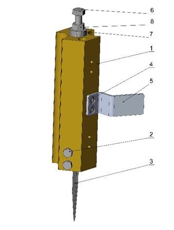
MATEC Web of Conferences 317, 06002 (2020)                          https://doi.org/10.1051/matecconf/202031706002
Power Transmissions 2020

      The structure of the shuttle was changed ("Drop
  mass" - NIJ 0115.00; "Missile" - HOSDB 2007.Part 3,
  keeping the total mass required by [3].
      3D models of the stand and the individual elements
  of its construction were developed. A computer
  simulation of the test process was performed.
      The stand can be used to pre-determine the stab
  resistance of different types of materials and their
  combinations used in the soft panels of the armor, in the
  process of refining their structure.
      The presence of such a stand in the equipment of the
  relevant company laboratories involved in the
  improvement of the structure of the soft panels of the
  bulletproof vests would reduce the costs and shorten the
  evaluation time of the tested samples in order to check
  their compliance with the standards, testing only in
  certified and accredited laboratories will only send
  samples that have the highest resistance to puncture.

  Acknowledgements: The author would like to thank the
  Research and Development Sector at the Technical University
  of Sofia for the financial support.

  References
  1.   V. Nikolova, Mat. used in mak. the s. pan. of the
       bulletproof vest. Adv. and disadv. Conference
       Proceedings "Metal Science, Hydro- and
       Aerodynamics, National Security 2014", ISSN:
       1313-8303, 405-409, Bulgaria (2015)
  2.   A. Bhnatagara, Material and technology.
       Lightweight ballistic materials, ISBN 978-5-94836-
       163-5, Technofer, Moscow (2011)
  3.   NIJ 0115.00., Stab Resistance of Personal Body
       Armor, (NIJ, Science and Technology, Washington,
       DC 20531, 2000)
  4.   J. Croft, D. Longhurst, HOSDB Body Armor
       Standards for UK Police, Part3: Knife and Spike
       Resistance, Publication No. 39/07/C (2007)
  5.   M. J. Pettit, J. Croft, PSDB Stab resistance standard
       for body armor, Police Scientific Development
       Branch, Publication No. 6/99, (1999)
  6.   SolidWorks, Software program, published by
       Dassault         Systèmes,      (Retrieved       from
       https://www.solidworks.com/sw/education/SDL_for
       m.html, 2017)

                                                                5
You can also read