Modeling and Simulation as Enablers for the Smart Grid - Georg Frey, 2018-05-15 Helsinki, Finland
←
→
Page content transcription
If your browser does not render page correctly, please read the page content below
Modeling and Simulation as Enablers
for the Smart Grid
Georg Frey, 2018-05-15
Helsinki, Finland

                                      Facilitator
Modeling and Simulation as
Enablers for the Smart Grid
The optimization and control of energy systems is a key topic these
days. In order to achieve a high penetration of renewables and at the
same time keep the systems stable and efficient, intelligence is
implemented on different levels (smart home, smart city, smart grid).
Models of the systems help in layout, control design and prediction. For
system layout.

In the talk some general issues of modeling and simulation are
discussed. The ideas are explained using examples from current
research projects.

                                 Facilitator

                                                                2018-05-15 | Page 2
Saarland University | Chair of
Automation and Energy Systems
Saarbrücken, located in the heart of Europe           Saarland University
•  Two hours by train to Paris and Frankfurt          • 18.000 students (17% international)

•   200 000 inhabitants                               • 279 professors, 1.300 academic staff

                                        Facilitator

                                                                                    2018-05-15 | Page 3
Modeling and Simulation

                     Facilitator

                                   2018-05-15 | Page 4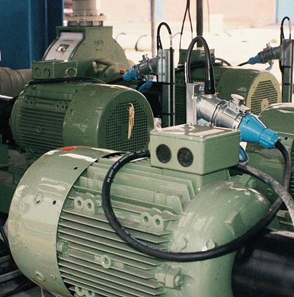
Different Models for the same
System
Model: suitable description of a system based on its
•  Structure
•  Behaviour
What is “suitable” depends on the purpose of the model
                                                                                        ➢ E-Motor-Modell des Regelungsingenieurs:

                                                                                            El. Strom i,                    Lastmoment ML
                                                                                           Spannung u
                                                                                                                            Drehzahl w
Example:
Industrial                                                                                  Fragestellung: Zus.hang zw. i, u, ML, w ?
Drive
                                                                                       ➢ E-Motor-Modell des Bauingenieurs:

                                                                                          El. Strom i,
                                                                                          Spannung u                          Lastmoment ML
                      Source: http://news.directindustry.de/press/marechal-electric/
                       stillstandszeitkosten-mit-elektrischem-marechal-verringern
                                            -9284-35062.html                                               F1        F2
                                                                                           Fragestellung: Welche Kräfte wirken auf
                                                                Facilitator
                                                                                                          das Fundament?
                                                                                                                       2018-05-15 | Page 5
Questions on Modeling

Q1: What has to be modeled?

Q2: How can it be modeled?

Q3: How can it be shared?

Q4: How to handle complexity?

Q5: How to couple existing models?

                                Facilitator

                                              2018-05-15 | Page 6
Q1: What has to modeled?

Modeling always locks at an abstracted part of the world

Models have a purpose (simulation, formal analysis, design, …)

Modeling is Engineering not Science!

Usefulness instead of Truthfulness

BUT also Correctness

                                 Facilitator

                                                                 2018-05-15 | Page 7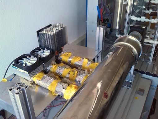
Q2: How can it be modeled?

Notations and tools

Again a question of what is the purpose of the model

Some notations allow the use of several tools; some tools support
several notations

Problem: We all have our preferred notations and tools

Is it a good idea to model a simple differential equation by a complex
hybrid Petri net?

                                 Facilitator

                                                                 2018-05-15 | Page 8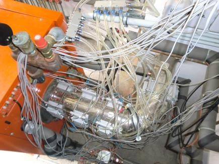
Q3: How can it be shared?

Sustainability

Multi-Domain Engineering and Modeling

Model-Exchange

Tool-Coupling vs. Model-Coupling

STANDARDS for Model-Interchange (e.g. FMI)

STANDARDS for Notation (e.g. Modelica)

                               Facilitator

                                             2018-05-15 | Page 9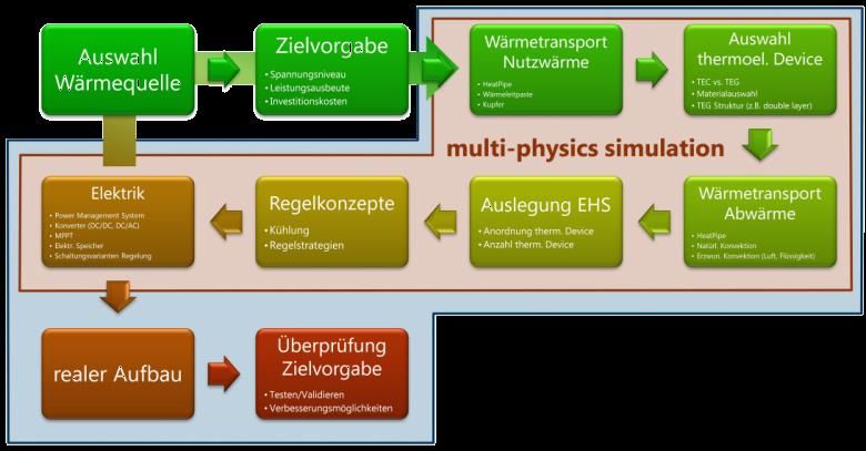
Q4: How to handle complexity?

                      Facilitator

                                    2018-05-15 | Page 10
Q5: How to couple the existing
models?
Signal-Flow
▪ uni-directional
▪ Information
▪ explicit causality
▪ Functional composition (process)
Energy-Flow
▪ direction-free
▪ Energy
▪ no explicit causality
▪ Spatial composition (system)
Example: Motor vs. Generator
Facilitator
2018-05-15 | Page 11Signal-flow based approach:
causality of elementary blocks
In a signal-flow based block diagram, the outputs of a block
are calculated from the given inputs of the block.
Calculating an unknown input is not supported using this approach.
given wanted
Facilitator
2018-05-15 | Page 12Example: signal-flow based model
of an electrical circuit
Output i(t) i1 + i2 = i
1 1 1
Input u(t)
R1i1 +
C
i1 dt = u i1 = u −
R1 C
i1 dt
= (u − R2i2 )
di di2 1
R2i2 + L 2 = u
L=5
dt dt L
Simulink®-block diagram:
i2
i1
Facilitator
2018-05-15 | Page 13Limitations of Signal-flow based
Modeling
Missing flexibility
Lots of manual work in changing models
Domain-free (everything converted to pure math)
To get rid of the domain-binding and the signal-oriented models the
idea of Bond-Graphs is used
To add flexibility and changeability OO-concepts are added
Solution: Modelica Language
Facilitator
2018-05-15 | Page 14Equation-based approach: acausal
modeling
• Connection between objects represents physical structure of the system
➢ Interface variables may have a physical meaning
➢ No separation between input and output variables (no causality)
➢ Classifying the interface variables into
Flow variables q: Junction
add up to zero at an ideal junction, i.e. qA qB
qA + qB + qC = 0, A B
jA jB
and Interfaces
(„Connectors“)
Potentials j : jC qC
have the same value at an ideal junction, i.e..
j A = j B = jC C
The objects contain systems of equations (and, possibly, algorithms)
defining their internal behaviour.
Facilitator
2018-05-15 | Page 15Potentials and Flows
Physical domain Potentials Flows
➢ Electricity Electrical potential Electrical current
➢ Translational mechanics Position, velocity Force
➢ Rotational mechanics Angle, angular velocity Torque
➢ Hydraulics Pressure Volume-/mass flow
➢ Pneumatics Pressure Mass flow
➢ Thermodynamics Temperature Heat flow
Universal physical principle:
• Differences in potential drive flows subject to conductances/resistances
• Flows determine temporal derivation of potential of energy storing elements
Facilitator
2018-05-15 | Page 16Example: object-oriented modeling
of the electrical circuit Model classes used for composing the model
u = j+ −j−
i = i+
0 = i+ + i−
Ri = u
Modelica®-object diagram:
u = j+ −j−
i = i+
0 = i+ + i− 3 identical equations
i = C du / dt in all components with
two poles
u = j+ −j−
i = i+
0 = i+ + i− Inheritance from
u = L di / dt common base class
u = j+ −j−
i = i+
0 = i+ + i−
u = u + uˆ sin(2πft + )
j+ = 0
0 = i+
Facilitator
2018-05-15 | Page 17Resulting Model
WOW!!! Thats complex and multi-domain ;-)
Facilitator
2018-05-15 | Page 18More complex and multi-domain
Well Better!!! But this is not
Exactly an energy system???
Facilitator
2018-05-15 | Page 19Energy: Waste Heat Recovery
Oil-fired heating
Exhaust pipe
Cooling system
a
a a
a IV
I b
II
III
b
b
b
pTEGs
Facilitator
2018-05-15 | Page 20Distributed Energy Systems–
Design and Control (I/II)
Energy flows
Electrical Thermal Mechanical
Wind Photo- Material flows El. Grid
Power H2O O2 CO2
voltaic Air H2 CH4 (Methane)
Plant Plant
Gas
Grid
Air H2O
O2 CO2
Compressor Electrolysi Eel
CO
station s Separation
2
El. Cons.
H2
CO2 Methan
Compr. CHP Th. Cons.
i-zation CH4 Eth
air
ORC / Compr. Air ORC / ORC / DC Grid
= (24 V)
TEG Consumer TEG TEG
Facilitator
2018-05-15 | Page 21Distributed Energy Systems–
Design and Control (II/II)
Defining appropriate levels of abstraction depending on the respective task:
Whole-system design, profitability predictions by long-term simulations
→ numerically efficient models with partially abstracted physics
Analysis and control of transient component dynamics by short-term simulations
→ physically detailed, dynamic models
Example: Component-based DES model in Dymola®/Modelica®
▪ Physically abstracted model
▪ Representation of physical layout
▪ Collection of essential component
parameters defining most relevant
operation scenarios
▪ Balancing of energy, material, and
related cost flows
Facilitator
2018-05-15 | Page 22MOCES: Modeling of Complex
Energy Systems (I/II)
Challenge Goal
Modeling and simulation of multi energy systems (electric Development and implementation of appropriate
grid | natural gas | heat ) within one modeling and modeling and simulation approach
simulation framework covering the four domains:
▪ Physical behavior
▪ Roles and individual behavior
▪ Prediction of consumption/ production
▪ Trading at energy markets
▪ Clearing of balance energy
▪ Optimization of virtual power plant
▪ Influence of boundary values (Weather
conditions)
▪ Communication of the involved entities
> Feedback loops between these domains
Facilitator
2018-05-15 | Page 23MOCES: Modeling of Complex
Energy Systems (II/II)
Influence of renewable energy
generators on (local) energy markets
Facilitator
2018-05-15 | Page 24Basispräsentation
The DESIGNETZ Vision

                   Facilitator
Consortium
31 Partners 15 associated Partners/ sub-contractors
Spanned Region (NRW, RLP, SL)
Key Figures
Project Start 2017-01-01
Runtime 4 Years
Volume 66 M€
Funding 30 M€
Facilitator
2018-05-15 | Page 27The Distribution Grid is the
Backbone of the Energy Transition
Extra High Voltage
High Voltage
Transmission Grid
ENERGY TRANSITION
Medium Voltage
Distribution Grid
Low Voltage
Facilitator
TT.MM.JJJJ | Page 28The Distribution Network is the
Backbone of the Energy Transition
Extra High Voltage
High Voltage
Transmission Grid
Medium Voltage
Distribution Grid
Low Voltage
More than 90% of renevable
energy in Germany is fed
into the distribution grid
Facilitator
TT.MM.JJJJ | Page 29Key Concepts in DESIGNETZ
• Decentralization
• Computation instead of Copper
• Flexibility
• Sector Coupling
FacilitatorDecentralization
Facilitator
2018-05-15 | Page 31Computation instead of Copper
System-Cockpit
Flexibilitätsoptionen Angebot Abruf
Ergebnis Anfrage Services
Überregionale AP6
DK
D20
Regionale Daten Services Security &
D16 • Speicherung, Verwaltung • Flex-Cockpit: • Netzberechnung
DK
und Bereitstellung der Daten Flexibilitäts-Monitoring • Simulation as a Service
Privacy
• Austausch von Daten für das Angebot und -Management • Model as a Service Kernel und sichere
und den Abruf von Flexibilität • Prognose PV • … Infrastruktur
• Prognose Lastgang Rollen & Rechte
Lokale DK Privacy & Schutz
Privathaushalt
DSSB
Flexibilitätsoptionen Angebot Abruf
Anfrage Ergebnis (Prognosen, Simulation) Services
Demos
Facilitator
2018-05-15 | Page 32Flexibility
Flexibilitätspotential
% 100 % 70
80 50
→
60 30
40 10 t
20 -10
0
t -30
Normaler Fahrplan der Technischen Anlage Technisch realisierbare Leistungsänderung
Mögliche Fahrweise mit geminderter Last der technischen Anlage gegenüber Fahrplan
Maximalleistung Flexibilitätspotenzial durch Leistungssteigerung
Leistungsaufnahme im Normalfahrplan Flexibilitätspotenzial durch geminderte Last
Modeling and Simulation allows Prediction of Flexibility Potential!
Facilitator
2018-05-15 | Page 33Sector-Coupling
(Electricity and Heat)
Roof-top PV-System
District Heating Simulation of Loads:
▪ Electrical
▪ Thermal (heating)
Provision of negativ electrical
▪ Warm Water
flexibility by electrical heating
element
Hot Water Storage Tank
Facilitator
2018-05-15 | Page 34Virtual Demonstrator in the
Dashboard
Facilitator
2018-05-15 | Page 35Modelling and Simulation as a
Service
Service User Modelling and Simulation as a Service Other Services
„Can the system
Model Virtual Representation of the real
provide the requested System
flexibility tomorrow?“ Describes the behavior based on
physical equations and parameters
Weather Prediction
API-request
Simulation
, ,…
Demand Prediction
Evaluation through user
or another service
Facilitator
2018-05-15 | Page 36Questions that MSaaS can Answer
(Example Solar System)
Facilitator
2018-05-15 | Page 37Thank you for your attention!
Prof. Dr.-Ing. Georg Frey
Chair of Automation and Energy Systems
Saarland University
Campus A5 1
66123 Saarbrücken, GERMANY
georg.frey@aut.uni-saarland.de
FacilitatorYou can also read