MAVIS: Conceptual architecture of the Instrument Control Software - mavis-ao
←
→
Page content transcription
If your browser does not render page correctly, please read the page content below
MAVIS: Conceptual architecture of the Instrument Control Software
                        B.Salasnich *a, A. Baruffoloa, A. Balestraa, D. Fantinela
       a
           INAF Astronomical Observatory of Padova, vicolo Osservatorio 5, 35122, Padova, Italy

                                                     ABSTRACT

In this paper, we describe the preliminary architecture of the Software for the Instrument Control System (ICSS) of
MAVIS, the new MCAO Assisted Visible Imager and Spectrograph for ESO’s Very Large Telescope. The instrument
successfully passed its phase A in May 2020 and will start phase B in March 2021. ICSS is in charge of controlling all
the motorized functions, managing the scientific exposures, monitoring the status of the system and coordinating the
sequence of operations from the Observing Blocks receiving to the collection of the scientific data. A challenge from the
SW point of view is that MAVIS, besides being an instrument for VLT, will use the ELT-SW framework, which is
currently under development. A dedicated ELT/VLT gateway will provide the interfaces with the Observation Handling
Subsystem (OHS), the Archive System, the Telescope Control System (TCS) and the AOF.
Keywords: Control software, instrument, VLT, ELT

                                               1. INTRODUCTION
The MCAO Assisted Visible Imager and Spectrograph (MAVIS) is a new instrument for ESO’s Very Large Telescope.
It will operate at the Nasmyth focus of Yepun telescope (UT4) and will include an imager and a dual-resolution dual-
band spectrograph. The instrument will operate in the visible band offering the opportunity to exploit in the 370-950 nm
range the image quality obtained with the combination of the Adaptive Optics Facility (AOF) of UT4 and of an inner
adaptive optics module, which includes two post-focal deformable mirrors. In this way the instrument can compensate
the effects of the atmospheric turbulence in MCAO mode and delivers a corrected field of view to the post focal
scientific channels, the imager (4Kx4K detector, 30x30 arcsec FoV) and the spectrograph (9Kx9K detector, 3x3 arcsec
FoV). The instrument successfully passed phase A in May 2020 and will start phase B in March 2021. In this paper, we
focus on the conceptual architecture of the Software for the Instrument Control System. The conceptual design of the
instrument is given in another paper1 of this conference.

                                        2. INSTRUMENT FUNCTIONS
MAVIS has a modular design and the Consortium has adopted an architectural philosophy to reflect this modularity.
Figure 1 shows a functional overview of the main MAVIS modules: adaptive optics module (AOM), imager,
spectrograph and calibration unit.
The AOM module6 is composed of the elements on the main optical bench from the entrance shutter to the science
output ports and includes two wave-front sensors (WFS) for laser (LGS) and natural (NGS) guide stars. The light coming
from the telescope enters the system through a shutter located at the Nasmyth focal plane. A field lens with active X/Y
position control compensates for pupil motion.

An insertable mirror is located after the shutter and injects the output of the calibration unit into the optical train.
Two Deformable Mirrors (DMs), conjugated to 6.0 and 13.5 km altitude, are set in the optical path to compensate for the
effects of atmospheric turbulence, together with the UT4 Deformable Secondary Mirror (DSM). A dichroic, with a
narrowband response near the 589nm sodium line, feeds then the LGS WFS sub-module in reflection. A linear stage
allows focus adjustment for the effective range of the sodium layer.

* bernardo.salasnich@inaf.it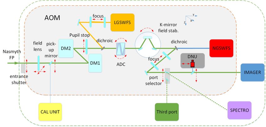
Figure 1. Illustration of the main modules and sub-modules of MAVIS: AOM, Imager, Spectrograph and Calibration Unit. The
figure shows in red the detail of the functions under SW control in the post-focal relay sub-module.

The LGSWFS sub-module is composed of an assembly of eight WFS cameras (one for each LGS), mounted on a
rotating carousel to compensate for the rotation of the laser asterism with the telescope elevation. Each camera has a
40x40 Shack Hartmann WFS.

Following the LGS dichroic, in transmission, a single Atmospheric Dispersion Corrector (ADC), corrects for
atmospheric dispersion over the full wavelength range, including the NIR. De-rotation of the science field is necessary,
as in all alt-azimuthal telescopes, since the pupil rotates differentially with respect to the science field. The AOM uses a
K-mirror to optically de-rotate the field.

A dichroic then separates the optical train, feeding the NIR light, in transmission, to the NGS WFS sub-module.
The NGSWFS sub-module is composed of three WFS elements, as illustrated in Figure 2. Each NGSWFS element uses a
pick-off mirror/probe and an XY translation stage to select a NGS from the 120” technical field of view. Moreover, each
NGSWFS element uses a “1x1” WFS to provide low order turbulence information and can alternately be configured to
provide truth sensing via a “2x2” Shack Hartmann WFS. The NGSWFS sub-module additionally incorporates a NIR
acquisition camera.

The NIR dichroic has the visible science beam in reflection. A focus stage enables adjustment of the science focus
independently of the NGS optical path. The light directs then to one of the scientific output ports: the imager and the
spectrograph. The AOM includes a third science output port. This port affords access to the MAVIS AO capabilities for
a possible future third ESO instrument, or for a visitor instrument.
Finally, an insertable mirror in the imager path can direct the light to a Diagnostics and Non Common-Path Aberrations
Unit (DNU). The DNU provides pupil-imaging capabilities and an on-axis Shack-Hartmann WFS for NCPA
determination.
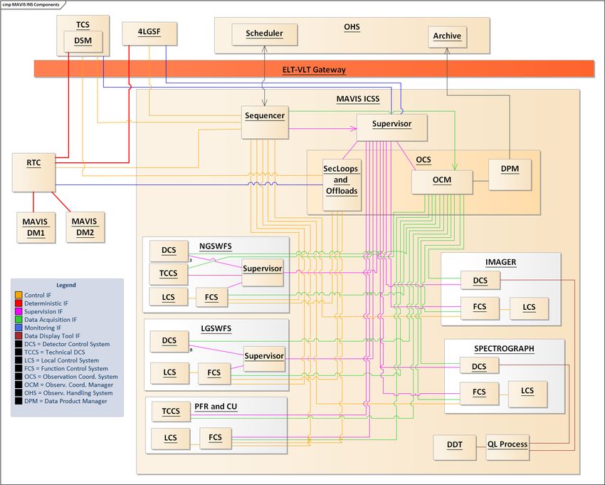
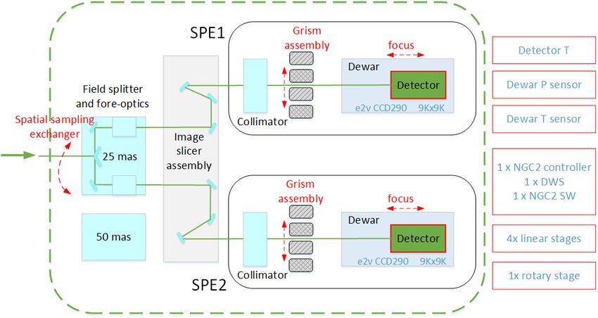
Figure 2. Schematic overview of the NGS WFS sub-module. The components under SW control are marked in red and summarized
on the right.

The Imager is located at the focal plane produced by the AOM and uses a 4K detector to image a ~30”x30” field. It
includes two filter wheels for broad and narrow band observations.
The Spectrograph design, see Figure 3, is composed of two spectrographs and fore-optics, which spatially split the input
field into two. The optics can switch between two spatial resolution modes (25/50 mas spaxels). Each spectrograph is
single arm. Moreover, each arm can operate at four different spectral resolutions by changing the disperser element.

  Figure 3. Schematic view of the spectrograph. Components under SW control are marked in red and summarized on the right.
3. CONTROL NETWORK
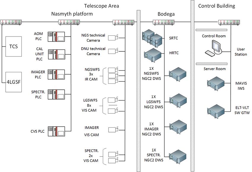
Figure 4. Control network architecture.
Figure 4 illustrates the control network architecture. MAVIS is controlled by one instrument workstation (MAVIS IWS)
located in the Control Building. It will be connected via Ethernet to the Real-Time Control system5 (RTC), depicted in
the figure as a cluster of Soft-RTC servers and the Hard-RTC and, we guess, hosted in the basement of the telescope
area, the so-called Bodega. The instrument workstation is connected to a dedicated server, which acts as ELT-VLT
gateway (GTW) and we guess located in the control room.
The MAVIS IWS will communicate with the detector workstations (DWS) for the control of LGSWFS, NGSWFS,
imager and spectrograph cameras. These Linux workstations are, at the moment, assumed to be located in the Bodega.
Commands from IWS to DWSs and from DWSs to the cameras will be transferred via Ethernet. We expect to use ESO
NGC2 controller to control the cameras.
During normal operations, no pixel/video data is expected to flow from the WFS cameras to the IWS. Pixel data will
flow directly to RTC. In this case, RTC will send decimated pixel data to IWS for display purposes. If further analysis
identifies a need, during maintenance operations a configuration change could allow pixel data to flow from the WFS
cameras to the IWS.
The Nasmyth platform will host the NGS acquisition camera and the DNU camera. In these cases, pixel data flow from
the cameras to the IWS. Moreover, the platform will host the detector front-end for scientific channels and for LGS/NGS
WFS and the Local Control Units.
In the current design, the instrument devices are controlled by four PLCs, one per post-focal science instrument, one
dedicated to AOM module and one to the Calibration Units elements.
Finally, scientific detectors and NGSWFS detectors will be set under cryogenic control. The Instrument Workstation will
access the CVS PLC to monitor the sensors of the cryo-vacuum systems.
4. INSTRUMENT SOFTWARE ARCHITECTURE
The control software will be based on the Instrument Control Framework2, which is currently under development by
ESO for the E-ELT.
Figure 5 illustrates the architecture of MAVIS ICSS, showing the main SW components and the different interfaces for
control (orange), supervision (magenta), data acquisition (green), monitoring (blue) and data display (brown).MAVIS ICSS is composed by a core of high-level components (Sequencer, Supervisor, OCS) that coordinate the observations and monitor and supervise the entire system; five subsystems will then interface with the instrument hardware: NGSWFS, LGSWFS, PFR-CU, IMAGER and SPECTROGRAPH. Calibration Unit, Post-Focal Relays devices and DNU assembly are seen here as one subsystem. Moreover, MAVIS ICSS interfaces with some VLT software components external to the instrument itself: the Observation Handling Subsystem (OHS), the Archive System, the Telescope Control System (TCS) and the UT4 laser guide-star facility (4LGSF). Figure 5. MAVIS Instrument Control Software architecture overview. 4.1 Coordination software The coordination software is composed of three main components, according to the current design of the ELT Observation Coordination Framework3: the Sequencer, the Supervisor and the Observation Coordination System (OCS). The Sequencer is in charge of receiving the observing blocks from the Observation Handling subsystem (OHS) of the VLT Data Flow System. It orchestrates the observations by sending control commands in sequence to external (TCS and 4LGSF) and internal components (RTC, FCSs). The Sequencer interfaces with the Supervisor, the OCS and each device through the Function Control System4 (FCS). All scripts interpreted by the Sequencer will be implemented in Python. The Supervisor is in charge to supervise the state of each component and of each sub-system.
The Observation Coordination System includes three components: the Observation Coordination Manager (OCM), the
Data Product Manager (DPM) and the “SecLoops and Offloads” component. The coordination manager OCM
coordinates the execution of the exposures, interfacing with each Detector Control System (DCS) and informing each
FCS of the start/end of an exposure. OCM interfaces with the data providers and the Data Product Manager, which
combines image files, produced by each DCS, with the metadata delivered by each subsystem and returns the produced
output, in FITS format, to the Data Flow System. Finally, the “Secondary loops and offloads” process, based on the
Guiding Manager of ESO Framework, receives periodically from RTC the corrections to be applied to a subset of
actuators. It interfaces with the telescope and the NGSWFS probes (offloads) and with the PFR de-rotator and the LGS
WFS focus device (secondary loops).

4.2 Sub-system software
The architecture of the five subsystems is similar. They include a FCS, which interfaces with the Local Control Units,
and one or more DCS, which interface with WFSs and scientific cameras. The Local Control Units include the low-level
software, which runs on Beckhoff PLCs.
In NGSWFS and “PFR and CU” a technical DCS will be present to control, respectively, an acquisition camera and a
multi-purpose technical camera.
In the case of NGSWFS and LGSWFS a local Supervisor will supervise their state. This choice is motivated by the fact
that these subsystems include more than one DCS, as there are three cameras in NGSWFS and eight LGSWFS.

4.3 ELT-VLT Gateway
MAVIS is a VLT instrument but MAVIS ICSS will be based on the SW framework for ELT. MAVIS ICSS will
interface with external components (OHS, TCS, 4LGSF) which are running under VLTSW. A dedicated ELT-VLT
gateway, provided by ESO, will enable the communication between the ELT communication layer (MAL) and the VLT
one (CCS), allowing interoperation with the telescope and the AO facilities at Paranal. High-speed control (connections
in red in Figure 5) will flow directly from the RTC to DSM/4LGSF.

                                                   REFERENCES

    [1]   Rigaut, F. et al., “MAVIS conceptual design”, Proc SPIE 11447-332 (this conference), 2020.
    [2]   ESO, ICS Framework Documentation, http://www.eso.org/~eeltmgr/ICS/documents/IFW_HL/sphinx_doc/html/
    [3]   ESO-306455, “ELT ICS Framework- Observation Coordination Framework Design”
    [4]   ESO-289629, “ELT ICS Framework- Function Control Framework Design”
    [5]   Gratadour, D. et al, “MAVIS Real-Time Control system”, Proc SPIE 11448-144 (this conference), 2020.
    [6]   Viotto, V. et al, “MAVIS: The Adaptive Optics Module feasibility study”, Proc SPIE 11448-9 (this conference),
          2020.
You can also read