Impact Factor: 7.569 Volume 10, Issue 10, October 2021 - Ijirset.com
←
→
Page content transcription
If your browser does not render page correctly, please read the page content below

Volume 10, Issue 10, October 2021

  Impact Factor: 7.569

International Journal of Innovative Research in Science, Engineering and Technology (IJIRSET)

                     | e-ISSN: 2319-8753, p-ISSN: 2347-6710| www.ijirset.com | Impact Factor: 7.569|

                                        || Volume 10, Issue 10, October 2021 ||

                                       | DOI:10.15680/IJIRSET.2021.1010083|

                 Modern Control Technique to
               Enhance Power Flow and Stability
                of Conventional HVDC System
                                   Chinthalapati Vasavi1 , Dr.K.Rama Sudha2
        P.G. Student, Department of EEE, Andhra University College of Engineering, Visakhapatnam, India1
           Professor, Department of EEE, Andhra University College of Engineering, Visakhapatnam, India2

ABSTRACT: With day-by-day growth in population, industrialization and technology the demand for electricity is
increasing enormously. Electricity is important part of modern life and it helps us in many ways. Electric power
transmission is one of the crucial part in power system network. Long distance AC transmission is subject to certain
problems which can be resolved with DC transmission.In transmission of bulk power, HVDC transmission has played a
major role from a very long time. HVDC Transmission has advantage of asynchronous operation and reduced
losses.This paper presents a simulation of CIGRE HVDC Benchmark system to transfer bulk amount of power between
two converter stations. To maintain constant power flow, power flow control is employed. The power flow control is
done by controlling the rectifier and inverter stations. In this paper to control power flow, Conventional controller of
HVDC station is replaced with Artificial neural network controller. This is performed by using the error signal obtained
from conventional controller and it is used to fed as input to ANN controller which produces alpha order signal to
generate firing pulses to the converter stations. Improvement in power flow during normal operating conditions and
stability during fault conditions is observed with Artificial neural network controller compared to conventional
controller.
KEYWORDS: CIGRE HVDC Benchmark System, converter stations, rectifier control, inverter control, error signal,
alpha order, Power flow, fault, Stability, Conventional controller, Artificial neural network controller
                                                  I. INTRODUCTION

High iand igrowing ielectricity idemands ineeds ithe itransmission iof ielectrical ipower iover ilong idistances.iRight-of
iway i(ROW) iand ibetter iefficiency iare isome iof ithe ichallenges ithat ihave ifaced ithe ipower itransmission
iindustry iover ithe iyears.iHigh iVoltage iDirect iCurrent i(HVDC) itechnology iis imainly iused iin ilong idistances
iand iit iis igaining ipopularity iover iAC itechnology iin ithis icontext.The modern form of HVDC employs the
technology that was developed and commercialized some 50 years ago by ABB company.iDC ipower itransmission iat
ilow ivoltages ihas ihigh ilosses iover ilong idistances, ithus igiving irise ito iHigh iVoltage iAlternating iCurrent
i(HVAC) ielectrical isystems.However HVAC transmission for long distances have many disadvantages
likesynchronous operation condition,high charging currents,skin and ferranti effect etc. These can be overcomed with
HVDC. With improvement in power electronic technologies these systems are highly improved. Fast and flexible
control helps to maintain stability.
                                        II. CIGRE HVDC SYSTEM MODEL

Considered system is a monopolar 500kv,1000 MW HVDC link with 12-pulse converters on both rectifier and inverter
side,connected to a weak ac system that provide a considerable degree of difficulty for dc controls[1].Reactive power
compensation and filters are provided on both sides.Thefepower icircuit iof ithe iconverter iconsists iof ithe ifollowing
isub icircuits.i

IJIRSET © 2021                                |   An ISO 9001:2008 Certified Journal |                             13869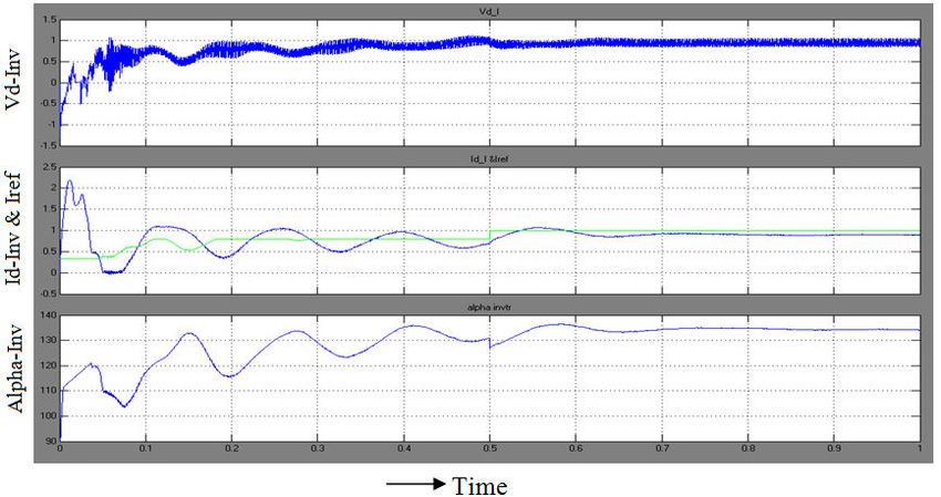
International Journal of Innovative Research in Science, Engineering and Technology (IJIRSET)

                     | e-ISSN: 2319-8753, p-ISSN: 2347-6710| www.ijirset.com | Impact Factor: 7.569|

                                         || Volume 10, Issue 10, October 2021 ||

                                        | DOI:10.15680/IJIRSET.2021.1010083|

         Ifddcccc            Fig 2.1 Single Line Diagram of CIGRE benchmark HVDC System i
a)
a) Three Phase Source
A ithree-phase iAC ivoltage isource iin iseries iwithian iR-L icombination iis iused ito imodel ithe isource.i
b) iAC iSide
          The iAC isides iof ithe iHVDC isystem iconsist iof isupply inetwork, ifilters, iand itransformers ion iboth
isides iof ithe iconverter.iThe iAC isupply inetwork iis irepresented iby ia iThevenin iequivalent ivoltage isource iwith
iequivalent isource iimpedance.iAC ifilters iareiadded ito iabsorb ithe iharmonics igenerated iby ithe iconverter ias
iwell ias ito isupply ireactive ipower ito ithe iconverter.
c)iDC iSide i
         The iDC iside iof ithe iconverter iconsists iof ismoothing ireactors ifor iboth irectifier iand ithe iinverter
iside.iThe iDC itransmission iline iis irepresented iby ian iequivalent iT inetwork, iwhich ican ibe ituned ito
ifundamental ifrequency ito iprovide ia idifficult iresonant icondition ifor ithe imodelled isystem.i
d)iConverter
           The iconverter istations iare irepresentediby i12-pulse iconfiguration iwith itwo isix-pulse ivalves iin
iseries.iIn ithe iactual iconverter, ieach ivalve iis iconstructed iwith imany ithyristors iin iseries.iEach ivalve ihas ia
i(di/dt) ilimiting iinductor, iand ieach ithyristor ihas iparallel iRC isnubbers.
e)Power iCircuit iModelling
         The irectifier iand ithe iinverter iare i12-pulse iconverters iconstructediby itwo iuniversal ibridge iblocks
iconnected iin iseries.iThe iconverter itransformers iare imodelled iby ione ithree-phase itwo iwinding itransformer
iwith igrounded iWye–Wye iconnection, ithe iother iby ithree-phase itwo iwinding itransformer iwith igrounded iWye–
Delta iconnection.iThe iconverters iare iinterconnected ithrough ia iT-network.

f)iUniversal iBridge iBlock
         The iuniversal ibridge iblock iimplementsia iuniversal ithree-phase ipower iconverter ithat iconsists iof isix
ipower iswitches iconnected ias ia ibridge.iThe itype iof ipower iswitch iand iconverter iconfiguration ican ibe iselected
ifrom ithe idialog ibox.iSeries iRC isnubber icircuits iare iconnected iin iparallel iwith ieach iswitch idevice.iThe
ivector igating isignals iare isix-pulse itrains icorresponding ito ithe inatural iorder iof icommutation.iThe
imeasurements iare inot irealized iin ithis imodel.

IJIRSET © 2021                                 |   An ISO 9001:2008 Certified Journal |                              13870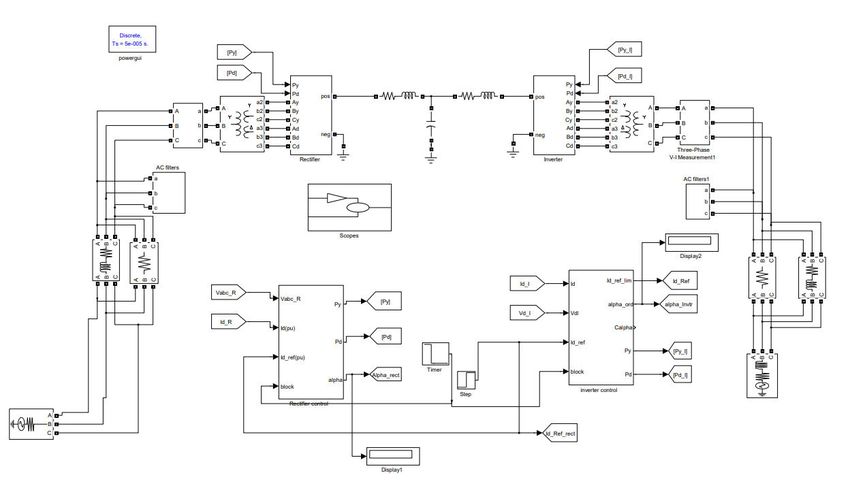
International Journal of Innovative Research in Science, Engineering and Technology (IJIRSET)

                        | e-ISSN: 2319-8753, p-ISSN: 2347-6710| www.ijirset.com | Impact Factor: 7.569|

                                               || Volume 10, Issue 10, October 2021 ||

                                              | DOI:10.15680/IJIRSET.2021.1010083|

                                          III. HVDC CONTROL CHARACTERISTICS
          In general control is applied to both the terminals. Under isteady istate, itypically irectifier iwould ibe iacti as
iconstant icurrent isource ii.e.iconstant icurrent icontrol iand iinverter iwill ioperate ias iconstant icounter ivoltage
isource ii.e.iconstant iextinction iangle.iThe icurrent iorder iat ithe irectifier iis idetermined iby ithe imanipulation iof
ipower iorder iand iinverter iDC ivoltage.iTo imaintain istability iat irectifier, iit iis inecessary ito ihave iless i(Idref i–
iId) ideviation iin iDC icurrent iand ialso i(γmeas- iγref) ideviations ishould ibe ikeep ias ilow ias ipossible ifor
iinverter istability.iThe iintersection iof itwo imodes igives inormal ioperation ipoint.

3.1 iControl iVariables ifor iConstant iPower iFlow iControl
          The icontrol imodel imainly iconsists iofi(α/γ) imeasurements iand igeneration iof ifiring isignals ifor iboth
ithe irectifier iand iinverter.iThe current equation for the control is as follows[6]
Id i=i(Edr icos iαr i– i Ediicos iγi) i/ i(Rcr i+ iRd- iRci)                     iiiiiiiii
Edr=i(Ar i*Er/ iTr) icos iαr                                                               i   iiiiiiiii
Edi=i(Ai*Ei/ iTi) icos iγi) i

                          TRANSFORMER                     RECTIFIER             INVERTER
                              TAPS                         ALPHA                 GAMMA

                                iiiiiiiiii
Following iare ithe icontrollers iused iin ithe icontrol ischemes:
     1.   Extinction iAngle i(γ) iController
     2.   iCurrent iController;
     3.   Voltage iDependent iCurrent iLimiteri(VDCOL).

3.2iRectifier iControl
           The irectifier icontrol isystem iuses iConstant iCurrent iControli(CCC) itechnique.iThe ireference ifor icurrent
ilimit iis iobtained ifrom ithe iinverter iside.iThis iis idone ito iensure ithe iprotection iof ithe iconverter iin isituations
iwhen iinverter iside idoes inot ihave isufficient iDC ivoltage isupport i ior idoes inot ihave isufficient iload
irequirement i.iThe ireference icurrent iused iin irectifier icontrol idepends ion ithe iDC ivoltage iavailable iat ithe
iinverter iside.iDC icurrent ion ithe irectifier iside iis imeasured iusing iproper itransducers iand ipassed ithrough
inecessary ifilters ibefore ithey iare icompared ito iproduce ithe ierror isignal.iThe ierror isignal iis ithen ipassed
ithrough ia iPIicontroller, iwhich iproduces ithe inecessary ifiring iangle iorder.iThe ifiring icircuit iuses ithis
iinformation ito igenerate ithe iequidistant ipulses ifor ithe ivalves iusing ithe itechnique.

                                                 Fig i3.1.iRectifier icontrol iwith iPI

IJIRSET © 2021                                        |    An ISO 9001:2008 Certified Journal |                          13871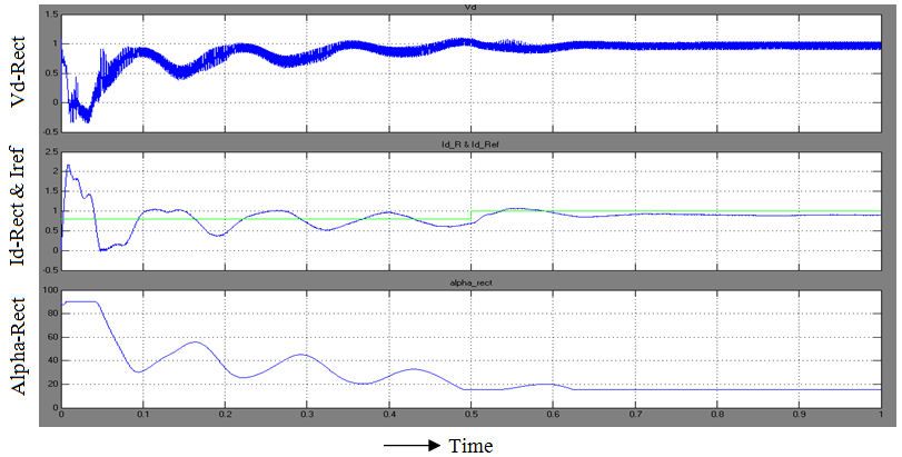
International Journal of Innovative Research in Science, Engineering and Technology (IJIRSET)

                     | e-ISSN: 2319-8753, p-ISSN: 2347-6710| www.ijirset.com | Impact Factor: 7.569|

                                        || Volume 10, Issue 10, October 2021 ||

                                       | DOI:10.15680/IJIRSET.2021.1010083|

3.3 Inverter iControl
          The iExtinction iAngle iControl ior iγ icontrol iand icurrent icontrol ihave ibeen iimplemented ion ithe
iinverter iside.iThe iCCC iwith iVoltage iDependent iCurrent iOrder iLimiter i(VDCOL) ihas ibeen iused ihere
ithrough iPI icontrollers.iThe ireference ilimit ifor ithe icurrent icontrol iis iobtained ithrough ia icomparison iof ithe
iexternal ireference i(selected iby ithe ioperator ior iload irequirement) iand iVDCOL i(implemented ithrough ilookup
itable) ioutput.iThe imeasured icurrent iis ithen isubtracted ifrom ithe ireference ilimit ito iproduce ian ierror isignal
ithat iis isent ito ithe iPI icontroller ito iproduce ithe irequired iangle iorder.iThe iγ icontrol iuses ianother iPI
icontroller ito iproduce igamma iangle iorder ifor ithe iinverter.iThe itwo iangle iorders iare icompared, iand ithe
iminimum iof ithe itwo iis iused ito icalculate ithe ifiring iinstant[5].

                           Fig i3.3.iInverter icontrol iwith igamma imeasurement itechnique
iThe icurrent iextinction itime iis idetermined ifrom ithe icurrent ithreshold.iThe isix igamma iangles iare idetermined
iusing isix ithyristor icurrents iand ithe isix icommutation ivoltages iare iderived ifrom ithe ithree-phase-to-ground iAC
ivoltages imeasured iat ithe i12 iprimary iof ithe iconverter itransformer.iThe iminimum igamma ivalue iis iconsidered
ifor ithe icontrol iaction.iFor ia i12-pulse iconverter, itwo igamma imeasurement iunits iare iused, iand ithe ismaller iof
ithe itwo igamma ioutputs iis icompared iwith ithe ireference igamma ito iproduce ithe ierror isignal.iThe ifiring iangle
iorders ifrom ithe iCCC iand ifrom ithe igamma icontroller i(CEA) iare icompared iand ithe iminimum iis iused ito
iproduce ifiring ipulses ifor ithe ivalve.

                                           Fig i3.4.iInverter icontrol iwith iPI.

IJIRSET © 2021                                |   An ISO 9001:2008 Certified Journal |                              13872
International Journal of Innovative Research in Science, Engineering and Technology (IJIRSET)

                       | e-ISSN: 2319-8753, p-ISSN: 2347-6710| www.ijirset.com | Impact Factor: 7.569|

                                          || Volume 10, Issue 10, October 2021 ||

                                          | DOI:10.15680/IJIRSET.2021.1010083|

                                    IV. ARTIFICIAL NEURAL NETWORKS
 4.1 Artificial Neurons
 Artificial Neural Networks are based on the neural structure of the brain. The brain basically learns from experiences. It is
 natural proof that are beyond the scope of current computers are indeed solvable by small energy efficient packages. This
 brain modelling also promises a less technical way to develop machine solutions.

                                            Figure 4.1. Artificial Neural Networks
 4.2 Training an Artificial Neural Network
 Once a network has been structured for a particular application, that network is ready to be trained. To start this process,
the initial weights are chosen randomly. Then, the training, or learning, begins. There are two approaches to training –
‘SUPERVISED’ and ‘UNSUPERVISED’. Supervised training involves a mechanism of providing the network with the
desired output either by manually “grading” the network’s performance or by providing the desired outputs with the inputs.
Unsupervised training is where the network has to make sense of the inputs without outside help. The vast bulk of networks
utilize supervised training[4].
           Typical diagrams for supervised training of a network is given in figure 4.2.

                                                Figure 4.2. Supervised training
           There are two types of training procedures according to the way in which the inputs are applied to the network.
They are ‘incremental training’ where each training pair will be applied one after the other and ‘batch training’ in which
entire set of training pairs will be applied at once[8]. The syntaxes for them are as below:

 IJIRSET © 2021                                  |   An ISO 9001:2008 Certified Journal |                            13873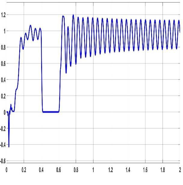
International Journal of Innovative Research in Science, Engineering and Technology (IJIRSET)

                         | e-ISSN: 2319-8753, p-ISSN: 2347-6710| www.ijirset.com | Impact Factor: 7.569|

                                             || Volume 10, Issue 10, October 2021 ||

                                             | DOI:10.15680/IJIRSET.2021.1010083|

 SYNTAX:

                Batch Training           :        net = train (net, p, t);

     Incremental Training       :      [net, a, e] = adapt (net, p, t)

4.3.Training Parameters

   SYNTAX                                         DESCRIPTION

net. trainparam.epochs                 indicates maximum number of epochs for training

net.trainparam.lr             specifies the learning rate

net.trainparam.goal           specifies the performance goal

net.trainparam.show                    specifies number of epochs between Showing progress

                                        V. SIMULATION MODEL AND RESULTS

                              Fig i5.1.iSimulink imodel iof CIGRE Benchmark iHVDC iSystem

 IJIRSET © 2021                                   |   An ISO 9001:2008 Certified Journal |                 13874
International Journal of Innovative Research in Science, Engineering and Technology (IJIRSET)

                     | e-ISSN: 2319-8753, p-ISSN: 2347-6710| www.ijirset.com | Impact Factor: 7.569|

                                         || Volume 10, Issue 10, October 2021 ||

                                        | DOI:10.15680/IJIRSET.2021.1010083|

                  Fig i(a).iRectifier iside iDC iVoltage, iDC iCurrent iand ifiring iangle iorder iwith iPI
From ithe iabove igraph iId_R iand iId_Ref iare icompared ito iproduce ian ierror isignal iwhich igives ithe ifiring iangle
iorderi(α=15.6 ideg).

                   Fig i(b).iInverter iside iDC iVoltage, iDC iCurrent iand ifiring iangle iorder iwith iPI
From ithe iabove igraph iId_I iand iId_Ref i iare icompared ito iproduce ian ierror isignal iwhich igives ithe ifiring
iangleiorder(αinv=134 ideg).

IJIRSET © 2021                                 |   An ISO 9001:2008 Certified Journal |                             13875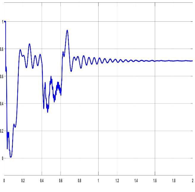
International Journal of Innovative Research in Science, Engineering and Technology (IJIRSET)

                   | e-ISSN: 2319-8753, p-ISSN: 2347-6710| www.ijirset.com | Impact Factor: 7.569|

                                      || Volume 10, Issue 10, October 2021 ||

                                     | DOI:10.15680/IJIRSET.2021.1010083|

                                Fig i5.2iRectifier icontrol iwith iNeural iNetworks.
   For inverter constant current control and constant extinction angle control is employed and minimum of them is
                                  considered as firing angle order as shown in fig.5.3

                                Fig i5.3.iInverter icontrol iwith iNeural iNetworks.

IJIRSET © 2021                              |   An ISO 9001:2008 Certified Journal |                           13876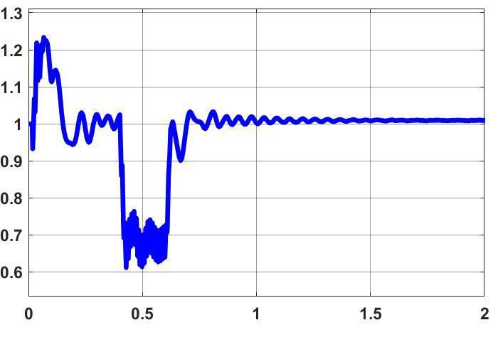
International Journal of Innovative Research in Science, Engineering and Technology (IJIRSET)

                      | e-ISSN: 2319-8753, p-ISSN: 2347-6710| www.ijirset.com | Impact Factor: 7.569|

                                           || Volume 10, Issue 10, October 2021 ||

                                          | DOI:10.15680/IJIRSET.2021.1010083|

                   Fig i(c).iRectifier iside iDC iVoltage, iDC iCurrent iand ifiring iangle iorder iwith iNN
From ithe iabove igraph iId_R iand iId_Ref iare icompared ito iproduce ian ierror isignal iwhich igives ithe ifiring iangle
iorderi(α=15.6 ideg).

                    Fig i(d).iInverter iside iDC iVoltage, iDC iCurrent iand ifiring iangle iorder iwith Inn

IJIRSET © 2021                                   |   An ISO 9001:2008 Certified Journal |                                     13877
International Journal of Innovative Research in Science, Engineering and Technology (IJIRSET)
| e-ISSN: 2319-8753, p-ISSN: 2347-6710| www.ijirset.com | Impact Factor: 7.569|
|| Volume 10, Issue 10, October 2021 ||
| DOI:10.15680/IJIRSET.2021.1010083|
Table i5.1.iComparison ibetween iPI iand iANN ifor iRectifier iFiring iAngle iα=15.50
Controller Rectifier iα Inverter iα i i Id_R(p.u) Id_I i(p.u) Vd_R(p.u) Vd_I i(p.u)
(degrees) i i(degrees)
With iPI 15.5 134 0.8954 0.8913 1.016 0.8582
With iANN 15.5 142 0.903 0.9024 0.96 0.95
From ithe iabove itable, ithe iDC icurrents iand ivoltages iof iboth irectifier iand iinverter iwith iANN ishows ibetter iresults
iwhen icompared iwith iPI icontroller.
Table i5.2.iEffect iDue ito iChange iin iRectifier iFiring iAngle iwith Ipi
Rectifier iα Inverter iα i i i Id_R i(p.u) Id_I i(p.u) Vd_R i(p.u) Vd_I i(p.u)
(degrees) i(degrees)
15.5 134 0.8954 0.8913 1.016 0.8582
30 128.6 0.8496 0.844 0.83 0.840
45 119.4 0.6294 0.6261 0.749 0.6825
60 109.9 0.3848 0.3989 0.358 0.35
75 98.62 0.2469 0.2394 0.28 0.26
Table i5.3.iEffect iDue ito iChange iin iRectifier iFiring iAngle iwith iANN
Rectifier iα Inverter iα i i i Id_R i(p.u) Id_I i(p.u) Vd_R i(p.u) Vd_I i(p.u)
(degrees) i(degrees)
15.5 142 0.903 0.9024 0.96 0.95
30 130 0.852 0.848 0.835 0.847
45 120.5 0.753 0.734 0.784 0.702
60 112 0.452 0.432 0.468 0.452
75 101 0.301 0.312 0.321 0.312
IJIRSET © 2021 | An ISO 9001:2008 Certified Journal | 13878International Journal of Innovative Research in Science, Engineering and Technology (IJIRSET)
| e-ISSN: 2319-8753, p-ISSN: 2347-6710| www.ijirset.com | Impact Factor: 7.569|
|| Volume 10, Issue 10, October 2021 ||
| DOI:10.15680/IJIRSET.2021.1010083|
Fig i5.4.iFault applied at both rectifer and inverter side
(a) (b)
Fig.(e) Voltage response with LG fault at rectifier side with a)PI controller b)ANN controller
IJIRSET © 2021 | An ISO 9001:2008 Certified Journal | 13879International Journal of Innovative Research in Science, Engineering and Technology (IJIRSET)
| e-ISSN: 2319-8753, p-ISSN: 2347-6710| www.ijirset.com | Impact Factor: 7.569|
|| Volume 10, Issue 10, October 2021 ||
| DOI:10.15680/IJIRSET.2021.1010083|
(a) (b)
Fig.(f). current response with LG fault at rectifier side with a)PI controller b)ANN controller
By observing fig( e) and fig (f) we can connclude that when LG fault is applied between 0.4 to 0.6 ,the system with ANN
controller recovered very quick when compared with PI controller.
Table 5.4. Effect due to LLLG Fault at Rectifier Side with PI and ANN
Controller FIRING Vdc_R Vdc_I Idc_R Idc_I Pdc_R Pdc_I
ANGLE
PI 15.5 0.7873 0.8579 0.6456 0.6606 0.5082 0.5667
ANN 15.5 0.9634 0.9563 0.9015 0.8991 0.8685 0.8598
(a) (b)
Fig (g) Rectifier voltage response with a)PI controller and b) ANN Controller
IJIRSET © 2021 | An ISO 9001:2008 Certified Journal | 13880International Journal of Innovative Research in Science, Engineering and Technology (IJIRSET)
| e-ISSN: 2319-8753, p-ISSN: 2347-6710| www.ijirset.com | Impact Factor: 7.569|
|| Volume 10, Issue 10, October 2021 ||
| DOI:10.15680/IJIRSET.2021.1010083|
Table 5.7. Voltage response parameters in rectifier side
Parameter PI Controller ANN Controller
Peak value 1.21 1.01
Peak overshoot 24.7 7.503
Rise time 1.905 0.92
Settling time 2 0.65
(a) (b)
Fig(h)Current response of rectifier with a) PI controller and b)ANN Controller
Table 5.7. Current response parameters in rectifier side
Parameter PI Controller ANN Controller
Peak value 1.0905 1.0905
Peak Overshoot 48.51 12.22
Rise time 2 0.8
Settling time 0.4 0.65
(a) (b)
Fig(i) Real Power Response with a)PI Controller and b)ANN Controller
IJIRSET © 2021 | An ISO 9001:2008 Certified Journal | 13881International Journal of Innovative Research in Science, Engineering and Technology (IJIRSET)
| e-ISSN: 2319-8753, p-ISSN: 2347-6710| www.ijirset.com | Impact Factor: 7.569|
|| Volume 10, Issue 10, October 2021 ||
| DOI:10.15680/IJIRSET.2021.1010083|
Table 5.8.Real power response parameters in rectifier side
Parameter PI controller ANN controller
Peak value 1.195 1.2
Peak Overshoot 30.46 8.006
Rise time 0.5 0.4
Settling time 2 0.8
VI. CONCLUSION AND FUTURE SCOPE
6.16.1.Conclusions
In ithis iproject,ia monopolar 500KVHVDC isystem iis idesigned ito icontrol ithe ipower iflow ibetween itwo
iconverter istations iwith iconventional icontroller iand iArtificial iNeural iNetworks.iFor irectifier iside icurrent
icontrol iis iused iand ifor iinverter iside iboth icurrent iand iextinction iangle icontrol iis iimplemented.iIn iorder ito
itransfer imaximum ipower iin ithe iDC ilink, iwe ihave ito imaintain iminimum ialpha.iThe ierror isignal iis ipassed
ithrough ia iPI iand iArtificial iNeural iNetworks icontroller, iwhich iproduces ithe inecessary ifiring iangle iorder.iThe
ifiring icircuit iuses ithis iinformation ito igenerate ithe iequidistant ipulses ifor ithe ivalves iin ithe iconverter
istation.Later LG and LLLG fault is applied to the system and response is observed for PI and ANN Controllers.
During steady state conditions, the power flow improvement with ANN controller is appreciable when
compared with PI controller.During fault conitions the recovery of the system post fault is drastically improved with
help of ANN controller. By observing the response parameters of the response one can clearly conclude ANN
controller has fast control action compared with PI. This inturn increases power system HVDC transmission stability.
6.2 iFuture iScope
The iscope ifor ifurther iwork iis ito icontrol ithe ipower iflow iin ithe iHVDC ilink iusing iFuzzy controller
and ANFIS(adaptive neuro fuzzy inference system) can be used.
VII. ACKNOWLEDGMENT
If words are considered as symbol of approval and tokens as knowledge, then let the words play the heralding role
of expressing my gratitude.
I would like to express my deepest gratitude to my guide, Dr. K. Ramasudha, Professor, Department of Electrical
Engineering, Andhra University College of Engineering (A), Visakhapatnam for her guidance. I shall always cherish
our association for her encouragement, approachability and freedom of thought and actions which I had enjoyed during
thesis work
I would like to thank all my friends, faculty members lab staff and everyone who helped indirectly for their good
wishes and constructive support in building up the work. At this point I have to express my indebtedness to my beloved
parents, for their blessings and encouragement in completing my work fruitfully.
REFERENCES
[1] M.iO.iFaruque, iYuyan iZhang iand iV.iDinavahi, i"Detailed imodeling iof iCIGRE iHVDC ibenchmark isystem
iusing iPSCAD/EMTDC iand iPSB/SIMULINK," iIEEE iTrans.iPower iDelivery, ivol.21, ino.1, ipp.i378 i–387,
iJan. i2006.
[2] Das,iB.P.; iWatson, iN.; iYonghe iLiu; i, i"Simulation istudy iof iconventional iand ihybrid iHVDC irectifier
ibased ion iCIGRÉ ibenchmark imodel iusing iPLL-less isynchronisation ischeme," iPower iEngineering iand
iOptimization iConference i(PEOCO), i2011 i5th iInternational i, ivol., ino., ipp.312-317, i6-7 iJune i2011doi:
i10.1109/PEOCO.2011.5970433.
[3] Ashfaq iThahir,iM.; iKirthiga, iM.V.;"Investigations ion imodern iself-defined icontroller ifor ihybrid iHVDC
isystems," iTENCON i2011 i- i2011 iIEEE iRegion i10 iConference, ivol., ino., ipp.938-943, i21-24 iNov.
i2011doi: i10.1109/TENCON.2011.6129248.
[4] Das,iB.P.; iWatson, iN.; iYonghe iLiu; i, i"Comparative istudy ibetween igate ifiring iunits ifor iCIGRE
ibenchmark iHVDC irectifier," iIndustrial iElectronics iand iApplications i(ICIEA), i2011 i6th iIEEE iConference
ion i, ivol.,no.,pp.299-306,21-23June2011 idoi: i10.1109/ICIEA.2011.5975598.
IJIRSET © 2021 | An ISO 9001:2008 Certified Journal | 13882International Journal of Innovative Research in Science, Engineering and Technology (IJIRSET)
| e-ISSN: 2319-8753, p-ISSN: 2347-6710| www.ijirset.com | Impact Factor: 7.569|
|| Volume 10, Issue 10, October 2021 ||
| DOI:10.15680/IJIRSET.2021.1010083|
[5] Sood, iV.K.; iKhatri, iV.; iJin, iH.; i, i"EMTP imodelling iof iCIGRE ibenchmark ibased iHVDC itransmission
isystem ioperating iwith iweak iAC isystems," iPower iElectronics, iDrives iand iEnergy iSystems ifor iIndustrial
iGrowth, i1996., iProceedings iof ithe i1996 iInternational iConference ion i, ivol.1, ino., ipp.426-432 ivol.1, i8-11
iJan i1996doi: i10.1109/PEDES.1996.539653.
[6] HVDC Transmission course from nptel.
[7] Kala iMeah, iA.H.M.iSadrul iUla, i"Simulation iStudy iof ithe iFrontier iLine ias ia iMulti-Terminal iHVDC
iSystem," iIEEE iPES iGeneral iMeeting, iJuly i20- i24, i2008, iPittsburg, iPA, iUSA.
[8] W.Miller,R.SuttonandP.Werbos,“NeuralNetworksforControl”,Cambridge,MA:MIT iPress, i1991
[9] E.iW.iKimbark, i"Direct iCurrent iTransmission," iVol.iI, iWiley-Inter-Science, iNew iYork, i1971.
[10]K.iR.iPadiyar, i"HVDC iPower iTransmission iSystems: iTechnology iand iSystem iInteractions," iNew iAgeI
Internationals i(P) iLimited iPublishers, iNew iDelhi, i1996. i
IJIRSET © 2021 | An ISO 9001:2008 Certified Journal | 13883You can also read