Installation tutorial for Console Customs Xbox 360 RFX-5D 5-mode Dual Rapid fire Microchip for CG and CG2 Wireless controllers
←
→
Page content transcription
If your browser does not render page correctly, please read the page content below
Installation tutorial for Console Customs Xbox 360
RFX-5D 5-mode Dual Rapid fire Microchip for CG and CG2 Wireless controllers
                      and all style Wired controllers
This tutorial is designed to aid you in installation of a console customs RFX-5D 5-mode Dual rapid fire microchip. This tutorial covers
      the installation of our new 8-pin chip which is able to detect the type of PCB your controller has and set itself up properly for it
     when properly installed. This simplifies the installation but installation must be done exactly as shown in this tutorial or your chip
                                                              will not work correctly.
This installation requires soldering several wires to extremely small confined spaces. We do not advise attempting this installation if
      you are a beginner at soldering. We recommend reading through all of the instructions and understand them before beginning
                                                              your installation.
   WARNING: Please proceed with this installation at your own risk. We will not be held responsible for any damage to
                        yourself, your controller, your Xbox 360 console or any other equipment.
                 This tutorial requires opening your controller which will void the warranty of your controller.

                                                                      Tools needed:
                              •    Torx T8 Security/tamper proof driver (For opening wireless controller)
                                     •           Soldering iron (A 5w/30w from radio shack is about $12)
                       •     Solder (We use rosin core solder from radio shack so there is no need for flux $4)
          •    Wire strippers (that can strip 30ga wire, a 30ga wire wrap tool from radio shack includes a 30ga stripper $8)
                                                                  •      Wire cutters
                                                                  •      Hot glue gun
                                             •      9/64th drill bit (or close to it a 1/8th will also work)
                                         •       Small pocket knife or razor blade (optional but helpful)

                                     Please visit our website at www.consolecustoms.net
                            Also visit our ebay store at http://stores.ebay.com/console-customs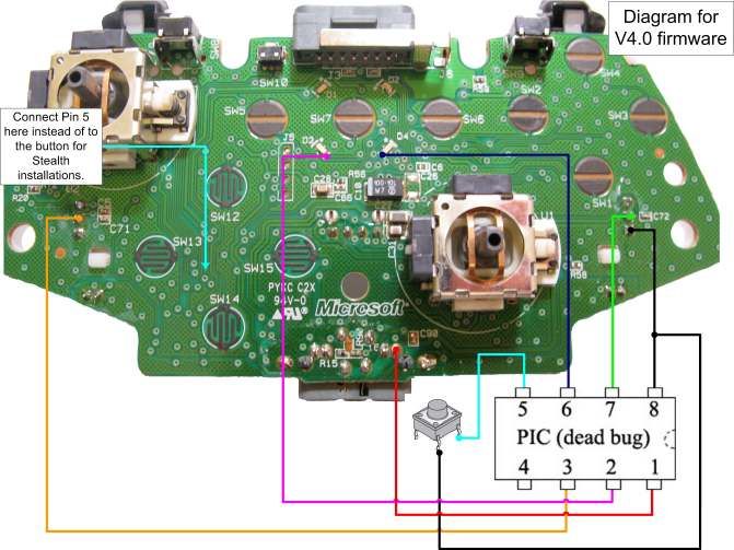
Controller Identification
• Before you get started you need to know which Controller type you have so that you can follow the correct tutorial for your
controller. Wired controllers will follow the CG/CG2 installation tutorial. The Left side images show the board from behind the battery
door (no need to open the controller) and the right side is with the controller open.

                                                             Matrix PCB
                                                      From the battery door area you
                                                          can see that there is no
                                                      Capacitor on the left side while
                                                     the other two versions do have a
                                                                 capacitor.

                                                               CG PCB
                                                      From the battery door area you
                                                       can see that the Capacitor is
                                                          horizontally oriented.

                                                              CG2 PCB
                                                      From the battery door area you
                                                       can see that the capacitor is
                                                            vertically oriented.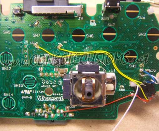
!!STOP!!
  This tutorial is for the CG and CG2 Wireless
  controllers and wired controllers only. If you
    identified your controller as a Matrix style
 wireless controller please visit our website and
 download the “RFX-5D Installation Tutorial for
     Matrix style wireless controllers” tutorial.

If you have a CG, CG2 or wired controller please
            continue to the next step.

               !!STOP!!
Step 1: First lets start by looking at what is in your kit.

•   You should have the following items in your kit
    1. (1) 8 pin PIC microcontroller
    2. (1) Buttons
    3. 30ga. Wire ( We include multiple colors)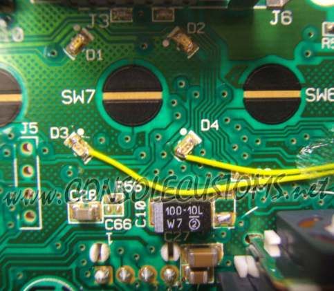
Step 2: You will start by taking the PIC chip and putting it on its back, also called
   (dead bug). Note the location of the notch that is on the top of the chip, the pin
   numbers and their purpose.
•   In this tutorial we will be using all of the pins except pin 4.

                                           Notch

                                                     1                Power
             Ground                    8
                                                                      To Player
           Output to                                 2
                                       7                              3 LED
         right trigger
                                                                      Output to
            To player                                3
                                       6                              Left trigger
             4 LED
           Input from                  5             4                Not used
             button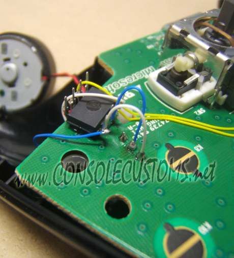
Step 3: You will now attach the wires to the chip using solder.
We use several color wires here to help show where each wire goes. Your kit will contain 2 colors of wire only.

• Starting with the left image:
     • Pin 1: This is the power wire and is red in the image, this wire should be aprox 5 inches long.
     • Pin 2: This is the Player 3 LED wire and is yellow in the image, this wire should be aprox 3 inches long.
     • Pin 3: This is the left trigger wire and is blue in the image, this wire should be aprox 5 inches long.
• Now the Right side Image:
     • Pin 5: This is the long white wire in the image and is for the button you will install, this wire should be aprox 4 inches long.
     • Pin 6: This is the long yellow wire in the image and is for the Player 4 LED, this wire should be aprox 4 inches long.
     • Pin 7: This is the short blue wire in the image and is for the right trigger, this wire should be aprox 3/4 of an inch long.
     • Pin 8: This is the short white wire in the image and goes to ground, this wire should be aprox 3/4 of an inch long.

•tip: Only strip about 1/8” of the wire for soldering. Exposing more bare wire could cause a short.
•tip: For information on proper soldering visit http://www.curiousinventor.com/guides/How_To_Solder

                                                Notch

                           4321                                                    Notch

                                                                                                  8765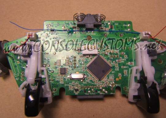
Step 4: Opening the controller
• Remove the 7 screws indicated below. One is behind the small white label.
• The wireless controller requires a T8 Torx security driver. This is a star shaped tip with a hole in the middle
of it. It is very difficult to open the wireless controller without this.

                                                     WIRELESS

                                                       SCREWS
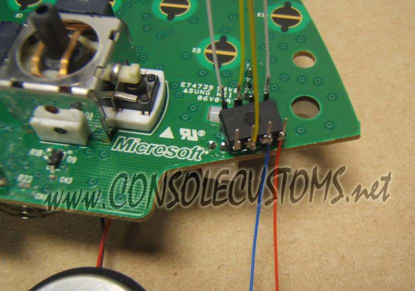
Step 5: Now we will attach the chip to the PCB using hot glue.
• Mount the chip on it’s back (dead bug) with hot glue so it is up against the white clip for the
trigger and the pins from the rumble motor plug.
• Note the orientation from the location of the notch that is on the top of the chip.

                                                                                        Notch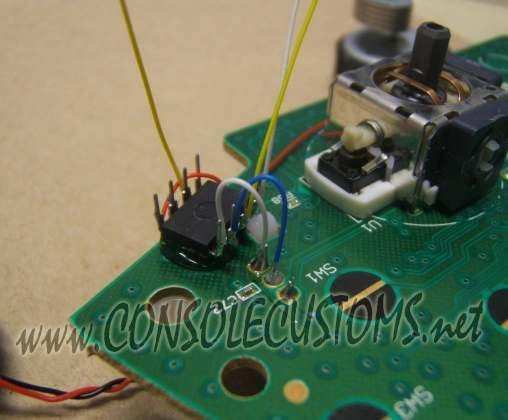
Step 6: Solder the left trigger wire.
• In this step you will need to take the wire from pin 3 and first run it along the bottom of the PCB as
shown in the left image. Use some hot glue to hold the wire in place so that it does not catch on
anything when putting the controller back together.
• Next trim the wire so that you do not have extra wire and strip only 1/8” of the end of the wire.
Then use your soldering iron to attach the wire to the middle of the three trigger pins as show in the
right side image.

Tip: trim you wires so they are only as long as you need, then strip the end and solder into place. Long wires will
just cause a place for something to snag when closing the controller.

        Hot glue Here
                                                                                                Solder to
                                                                                                middle of the
                                                                                                3 trigger pins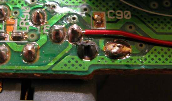
Step 7: Attaching the right trigger wire and ground wire.
• In this step you will first attach the blue trigger wire as shown in the left image to the middle of the
  three trigger pins for the right trigger.
• Next you will attach the white ground wire. This is the only step that requires a different solder
  point to be used for the wired controller.
     • For the CG and CG2 controllers use the bottom of the three trigger points as shown in the
       right side image.
     • For wired controllers use the Top of the three trigger points.
tip: keep your wires as short as possible so they do not interfere with the buttons when putting the controller back
  together.

Notch                                                      Notch

                                                            Ground for
                                                                                                    Ground for
                                                            CG and CG2
                                                                                                      wired
                                                              boards
                                                                                                    controllers
Step 8: Attaching the LED wires. • Now you will install the wires to control the Player 3 and 4 LEDs. Be sure to cut the wires to the exact length needed and keep the wire out of the black circles for the buttons. Getting to close to these could interfere with the operation of the buttons on the controller when you put it back together. • Solder the wire from pin 2 to the bottom of the player 3 LED and the wire from pin 6 to the bottom of the player 4 LED. You must be careful with this as the LED’s are very fragile and leaving your soldering iron on the end to long could damage the LED. Only touch the very end of the LED with your soldering iron. DO NOT touch the longer sides or the center of the LED because you will destroy it. •The right image show the path your wires should follow and the left is a close-up of the LED’s
Step 9: Attaching the power wire.
• Solder the wire from pin 1 to the power for the headset as shown. The bottom picture
shows a close-up of the solder point

Solder Here

                                                       Solder Here

                                                      Plastic clip from headset
Step 10: Onto the case and button. Here we will drill the hole needed for the
button and secure it in place. For stealth installation skip to step 12
• Drill a hole using your drill bit in the spot indicated or where ever you would like to have your button. We prefer
keeping it out of the way because you will only need to press it to change modes.
• Next take your button and we are going to remove one pair of legs REMOVE
because we only need one pair. Use the image to the right so you know which
legs to remove.
•Next use hot glue to secure the button in place. Do not attempt to use super glue
or other adhesives as it will soak into the button mechanism and cause it to stop
working. Once the button is secured in place bend the two legs out flat away from
the button.
• finally cut cut another small piece of wire about 2” long and solder to one leg of the
button. This will later be connected to the ground of the chip (pin 8).
Drill hole hereStep 11: We will now connect the wire from the chip to the button.
• flip over the controller PCB and bring it in close to the back half of the case. Take the one wire that
you have left (From pin 5) and solder it to the remaining pin of the button.
• Finally flip the PCB over onto the back of the case and attach the final wire from the button to the
ground of the chip (pin 8).
To ground
From Pin 5
Ground wire from button
attaches to pin 8Step 12: Stealth installation (using the sync button, for wireless controllers only)
• For an easier installation and stock controller look you can use the sync button instead of adding a button to your
controller. You can attach the wire to the middle pin of the sync button but we are going to show you an easier
spot.
• Run the wire from pin 5 along the same path as the wires for the player 3 & 4 LEDs then down in the middle of
the D-pad area making sure you don’t cross over any of the black circles on the PCB.
• To use this solder point you must first use a pocket knife to scrape off the green coating and expose the metal.
Try to only scrap off the area of the solder point only. Then use solder to attach the wire to this point.
• The locations for the sync button are different based on if you have a CG or CG2 style controller. Look at the
appropriate image below to find the correct solder point for your controller.
CG CG2
From Pin 5 From Pin 5Step 13: Almost done • Now onto the top of the case. To make it all fit we may have to make a little bit more room. Just to be sure I use a knife or side cutters to remove the plastic support shown in the image in red. This is the angled support for the right side rumble motor. • Depending on your button placement you may also need to remove part of the back support for the rumble motor. This is shown in green in the images. •The last thing you need to do is reassemble everything. The easiest way I have found to do this is leave the top piece face down so all the buttons do not fall out. And hold the PCB to the back of the controller and flip it over on the top of the case. Align the rumble motors so they are in their holders and lay the PCB and back of the case onto the front of the case. Keep it face down and use your finger to work the thumbsticks through the holes and work the case closed. Do not force it you may have wires preventing the case from closing entirely. Just go slow and look at any areas to see what is stopping it from closing all the way. •Now just screw your controller back together and your done! See the next page for additional information on using your new mod.
Installation Diagram
Xbox 360 RFX-5D Dual 5-mode rapid fire V4
•   This mod has many different features and functions which we will explain below. Video tutorials are available for all of these features on our website www.consolecustoms.com and
    from our YouTube channel www.youtube.com/consolecustoms.

•   Game Modes – This is where our mods truly excel, instead of having 7,8 or 10 speed to cycle through like you see on other mods. We break ours down into game modes. Each game
    mode contains a set of speeds that work for specific games. This way you have a smaller set of speeds to cycle through which all work for the game you are playing. This allows you to
    get to the speed you want to use or to turn off the rapid fire much faster.
    To switch the game mode you must HOLD down the mod button (sync button on stealth installs) for 3 seconds. After 3 seconds you will see the player 3 and 4 LEDs flash. The
    number of times the LED flashes indicates the game mode (ex. 1 Flash = Game Mode 1, 2 Flashes = Game mode 2, etc.) The mod will remember the game mode you have set even if
    you turn off your controller.

     • Game Mode 1: Call of Duty: 4 / Modern Warfare 2 / Black Ops
          – Speed 1 – Fast Rapid Fire
          – Speed 2 – Slow Rapid Fire
          – Speed 3 – 3-Round Burst Fire
     • Game Mode 2: Call of Duty: World at War
          – Speed 1 – Fast Rapid Fire
          – Speed 2 – Slow Rapid Fire
          – Speed 3 – 3-Round Burst Fire
     • Game Mode 3: Gears of War 2
          – Speed 1 – Hammer Burst/Slow Pistol Rapid Fire
          – Speed 2 – Fast Pistol Rapid Fire
     • Game Mode 4: Halo: 2 / 3 / ODST / Reach
          – Speed 1 – Fast Rapid Fire
     • Game Mode 5: User set from 6 to 25 shots per second. Programming instructions on next page.
          – Speed 1 – Standard Rapid Fire
          – Speed 2 – 3-Round Burst Fire

•   Speed Settings – Once you are in the game mode for the game you are playing you just need to TAP the mod button (sync button for stealth installs). Each time you tap the button it
    will change to the next speed setting which will be indicated by the player 4 LED flashing fast for the fast speed, slow for the slow speed, staying on solid for the 3-round burst and OFF
    when the rapid fire is off.

•   Enable/Disable the Left trigger – At any time you can enable or disable the left trigger rapid fire. To do this you must press and hold the button underneath the controller (or the sync
    button for stealth controllers) and while holding pull the left trigger. You will see the player 3 LED turn on and stay on solid for as long as the left trigger is enabled. To disable just
    follow the same process of holding the button and pulling the left trigger. This process is very fast and simple making it a great asset when switching to or from dual (akimbo) weapons.
    The dual rapid fire works for all speed settings but does not work for burst fire. Only the right trigger will work when using burst fire.

•   LED modes – By changing the LED mode you can change how the Player 4 LED reacts when you change the Rapid fire speed. There are three modes for the LED described below.
    To change the LED mode you must hold in the button (or sync button for stealth installs) while you are turning on the controller.

     • LED MODE 1 (default) - Blinking LED, the speed of blinking changes with the speed of rapid fire.
     • LED MODE 2 - Blink to solid LED, The LED will blink 1, 2 or 3 times depending on the mode then stay on solid.
     • LED MODE 3 - No LED, the LED will be off all the time. For the ultra stealth look.
Changing the User adjustable rapid fire speed
These instructions are also available as a video from our website www.consolecustoms.com and also our youtube
channel www.youtube.com/consolecustoms.
1. You first need to be in the user adjustable game mode. Use the procedure described on the previous page to switch the controller
to the correct mode.
2. Once in the user adjustable game mode. You will need to first hold in the trigger and while holding the trigger press and hold the
mode change button on the back. (or sync button for stealth controllers). You must hold in the trigger first, before pressing
and holding the button. If you do not follow this order you will just switch the game mode instead of entering to
programming mode.
3. Hold both the trigger and the button for aprox 3 seconds. After 3 seconds you will see the player 4 LED come on for 1 second
then go out. After you see this you can release both the trigger and the button. You are now in the programming mode.
4. When you enter the programming mode the user programmable speed is set back to 6 shots per second (166 milliseconds per
sot). This is so you always know where you are at and also allows the programming to be done with only using one button.
5. While in the programming mode every time you press the button on the back of the controller (sync button on stealth controllers)
the firing rate will increase by 2ms. The player 4 LED will also flash. The rate can be increased until you reach 25 shots per
second ( 40 milliseconds per shot). At this point the player 4 led will not flash and pushing the button will no longer increase the
speed.
6. At any time you can test you speed by just pulling the trigger.
7. Once you are at the desired speed follow steps 2 and 3 above to return to the user adjustable game mode.
Tips:
• Every time you enter the programming mode the speed is set back to 6 shots per second (166 milliseconds per sot)
• Remember or better yet write down the number of times you pressed the button. So you can go back and make adjustments if
needed.
• This mode works in milliseconds each time you press the button the speed is decreased by 2ms. So you can easily calculate you
speed.
• The default is 6 shots per second or 166ms. There are 1000 milliseconds in 1 second. So 1000/166 = 6.02 or approximately 6
shots per second.
• If you press the button 20 times you are now at 126ms. 1000/126 = 7.94 approximately 8 shots per second.
• If you want to go slower in speed you must exit and re-enter the programming mode and start over.You can also read