Application Note An_221 Adding An ADC To The Raspberry Pi
←
→
Page content transcription
If your browser does not render page correctly, please read the page content below
Future Technology Devices International Ltd.

                             Application Note

                                        An_221

    Adding An ADC To The Raspberry Pi
                             Document Reference No.: FT_000733
                                           Version 1.0
                                    Issue Date: 2012-08-02

           The Raspberry Pi is a single board computer based on an ARM processor aimed at
           teaching young people about computers and programming. FTDI have developed an
           expansion module for this Raspberry Pi, the RPI-Hub-Module. This application note
           explains how to use the RPI-Hub-Module as an SPI master to read an external ADC.
           Schematics and sample code will be provided.

Copyright © 2012 Future Technology Devices International Limited                               0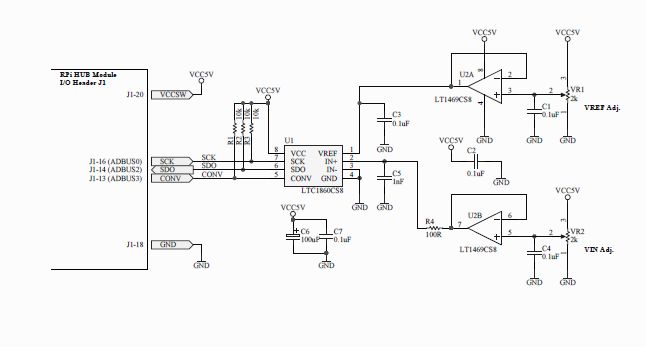
Adding an ADC to the Raspberry Pi
                                                                                            AN_221 AN_221
                                                                                                         Version 1.0

                                                          Document Reference No.: FT_000733 Clearance No.: FTDI# 311

Table of Contents
1     Introduction .................................................................... 2
    1.1    Overview ................................................................................... 2
    1.2    Scope ........................................................................................ 2
2     Hardware ........................................................................ 3
    2.1    Block Diagram ........................................................................... 3
    2.2    ADC schematic .......................................................................... 3
    2.3    Hardware Function.................................................................... 4
3     Drivers ............................................................................ 5
4     Application code .............................................................. 6
    4.1    Source Code .............................................................................. 6
    4.2    Compiling Source Code ............................................................. 6
    4.3    Running the example ................................................................ 6
5     Contact Information ........................................................ 9
6     Appendix A – References............................................... 10
    Document References ..................................................................... 10
    Acronyms and Abbreviations ........................................................... 10
7     Appendix B – List of Tables & Figures ........................... 11
8     Appendix C – Revision History....................................... 12

                   Copyright © 2012 Future Technology Devices International Limited                             1
Adding an ADC to the Raspberry Pi
AN_221 AN_221
Version 1.0
Document Reference No.: FT_000733 Clearance No.: FTDI# 311
1 Introduction
The Raspberry Pi is a single board computer (SBC) based on an ARM processor aimed at teaching young
people about computers and programming. FTDI have developed an expansion module for this Raspberry
Pi based on the FT2232H, the RPI-Hub-Module. This application note explains how to use the RPI-Hub-
Module as an SPI master to read an external ADC. Schematics and sample code will be provided.
1.1 Overview
The Raspberry Pi is a single board computer primarily running Linux OS. The board has a number of IO
ports for developing applications with, including 2 USB host ports. With the RPI-Hub-Module connected to
the Raspberry Pi USB port, FTDI can demonstrate using an FTDI chipset operating on an ARM processor
running Linux to expand the IO options of the Raspberry Pi while also offering buffered protection to the
processor from badly connected external peripherals.
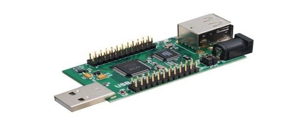
The RPI-Hub-Module is a FT2232H based design allowing for
2 independent interfaces which may be configured for GPIO,
UART, FIFO, I2C or SPI etc. The module also includes a USB
hub creating an additional 2 USB host ports. More
information on the hub can be found here.
Figure 1.1 RPI-Hub-Module
More information on the Raspberry Pi can be found here.
1.2 Scope
This application note assumes the user has already created a working Linux image on an SD card and the
Raspberry Pi is already functional.
This application note will show how to connect the RPI-Hub-Module to the Raspberry Pi and install FTDI
drivers to control the module. The application note will then explain how the module may be used to read
values from an external ADC device over the SPI interface.
Copyright © 2012 Future Technology Devices International Limited 2Adding an ADC to the Raspberry Pi
AN_221 AN_221
Version 1.0
Document Reference No.: FT_000733 Clearance No.: FTDI# 311
2 Hardware
2.1 Block Diagram
The setup for this reference design is as shown in the following block diagram.
DISPLAY
HDMI
USB
Keyboard
USB
RASPBERRY Pi RPI-Hub-Module
USB
Mouse
SPI
ADC Board
Figure 2.1 Block Diagram
The red block is the Raspberry Pi small board computer where the code is running.
The blue blocks are standard PC peripherals, although note the display requires an HDMI input.
The green blocks are developed by FTDI.
2.2 ADC schematic
The schematic for the ADC board in the setup is shown here.
Figure 2.2 ADC Board schematic
Copyright © 2012 Future Technology Devices International Limited 3Adding an ADC to the Raspberry Pi
AN_221 AN_221
Version 1.0
Document Reference No.: FT_000733 Clearance No.: FTDI# 311
2.3 Hardware Function
The hardware operates by providing a supply input to a Linear Technologies LTC1860 – 12 bit,
250ksamples/s ADC.
Variable resistor VR1 provides a reference input and variable resistor VR2 provides the changing input.
The LTC1860 coverts this input to a digital value transferred over SPI to the FT2232H on the RPI-Hub-
Module which can be read by the Raspberry Pi processor to allow for values to be shown on the display.
Copyright © 2012 Future Technology Devices International Limited 4Adding an ADC to the Raspberry Pi
AN_221 AN_221
Version 1.0
Document Reference No.: FT_000733 Clearance No.: FTDI# 311
3 Drivers
When the hardware is all connected, the RPI-Hub-Module requires FTDI drivers to be loaded to access the
FT2232H functions. This application is using the Multi-Purpose-Synchronous-Serial-Engine (MPSSE) of the
FT2232H and as such requires the D2xx driver to be loaded. As this is a “user mode” driver as opposed to
a “kernel mode” driver the installation is simply a case of copying the file to the Rapsberry Pi SD card and
making a symbolic link as described below.
Using the internet browser on the Raspberry Pi, download the driver file onto the SD card from
http://www.ftdichip.com/Drivers/D2XX/Linux/libftd2xx1.1.12.tar.gz
(note this is driver version 1.1.12 – check for later versions when performing this step).
Open a terminal window. This is one of the applications provided with the basic Rapsberry Pi kernel.
In the terminal window use the “cd” command to move to the folder where the downloaded file was
saved to.
Now type the following commands:
1. tar xfvz libftd2xx1.1.12.tar.gz
This unpacks the archive, creating the following directory structure:
build
arm926
i386
x86_64
examples
libusb
ftd2xx.h
WinTypes.h
2. cd build/arm926
3. sudo -s
or, if sudo is not available on your system:
su
Promotes you to super-user, with installation privileges. If you're
already root, then step 3 (and step 7) is not necessary.
4. cp lib* /usr/local/lib
Copies the libraries to a central location.
5. chmod 0755 /usr/local/lib/libftd2xx.so.1.1.12
Allows non-root access to the shared object.
6. ln -sf /usr/local/lib/libftd2xx.so.1.1.12 /usr/local/lib/libftd2xx.so
Creates a symbolic link to the 1.1.12 version of the shared object.
7. exit
These instructions can be found online at:
http://www.ftdichip.com/Drivers/D2XX/Linux/ReadMe-linux.txt
Copyright © 2012 Future Technology Devices International Limited 5Adding an ADC to the Raspberry Pi
AN_221 AN_221
Version 1.0
Document Reference No.: FT_000733 Clearance No.: FTDI# 311
4 Application code
4.1 Source Code
The application code was developed in C and is available as source code from the link here.
The application uses the basic D2xx function calls:
FT_ListDevices – to detect the device connected
FT_Open – to open a handle to the device interface for further commands to be sent to.
FT_Purge – cleans out the buffers to prevent erroneous data at the start.
FT_SetBitMode – to access MPSSE mode
FT_Read – To read the ADC data
FT_Write – To send commands to the FT2232H MPSSE
FT_Close – To close the handle
How to use these function calls are all defined in the D2xx Programmers Guide.
The instruction set for MPSSE is defined in
AN_108_Command_Processor_for_MPSSE_and_MCU_Host_Bus_Emulation_Modes.pdf
4.2 Compiling Source Code
On a linux machine the executable file is termed an object file with the extension .o.
To create the object file from the source code (extension.c) the user must use the terminal window to
browse to the folder containing the file and then use the following command:
gcc main.c –o adc –Wall –Wextra –L. –lftd2xx –ldl –lpthread –lrt –Wl,-rpath /usr/local/lib
(note gcc is the compiler tool and should be part of the basic kernel)
The output of this will be a file named adc.o in the same folder as main.c.
4.3 Running the example
To run the example the FTDI Virtual Com Port (VCP) driver must be unloaded. This loads by default when
an FTDI device is plugged in as it is part of the kernel.
In the terminal window send the following commands.
sudo rmmod ftdi_sio
sudo rmmod usbserial
Now run the application with the command
sudo ./adc
The value from the ADC will now be printed on the display. The user can adjust the variable resistor and
repeat the reading. This should change the value printed on the display.
Copyright © 2012 Future Technology Devices International Limited 6Adding an ADC to the Raspberry Pi
AN_221 AN_221
Version 1.0
Document Reference No.: FT_000733 Clearance No.: FTDI# 311
5 Contact Information
Head Office – Glasgow, UK Branch Office – Hillsboro, Oregon, USA
Future Technology Devices International Limited Future Technology Devices International Limited (USA)
Unit 1, 2 Seaward Place, Centurion Business Park 7235 NW Evergreen Parkway, Suite 600
Glasgow G41 1HH Hillsboro, OR 97123-5803
United Kingdom USA
Tel: +44 (0) 141 429 2777 Tel: +1 (503) 547 0988
Fax: +44 (0) 141 429 2758 Fax: +1 (503) 547 0987
E-mail (Sales) sales1@ftdichip.com E-Mail (Sales) us.sales@ftdichip.com
E-mail (Support) support1@ftdichip.com E-Mail (Support) us.support@ftdichip.com
E-mail (General Enquiries) admin1@ftdichip.com E-Mail (General Enquiries) us.admin@ftdichip.com
Branch Office – Shanghai, China
Branch Office – Taipei, Taiwan
Room 1103, No. 666 West Huaihai Road,
Future Technology Devices International Limited Shanghai, 200052
(Taiwan) China
2F, No. 516, Sec. 1, NeiHu Road Tel: +86 21 62351596
Taipei 114 Fax: +86 21 62351595
Taiwan , R.O.C.
Tel: +886 (0) 2 8791 3570 E-mail (Sales) cn.sales@ftdichip.com
Fax: +886 (0) 2 8791 3576 cn.support@ftdichip.com
E-mail (Support) cn.admin@ftdichip.com
E-mail (Sales) asia.sales1@ftdichip.com E-mail (General Enquiries)
asia.support1@ftdichip.co
E-mail (Support)
m
E-mail (General Enquiries) asia.admin1@ftdichip.com
Distributor and Sales Representatives
Please visit the Sales Network page of the FTDI Web site for the contact details of our distributor(s) and
sales representative(s) in your country.
System and equipment manufacturers and designers are responsible to ensure that their systems, and any Future Technology Devices
International Ltd (FTDI) devices incorporated in their systems, meet all applicable safety, regulatory and system-level performance
requirements. All application-related information in this document (including application descriptions, suggested FTDI devices and other
materials) is provided for reference only. While FTDI has taken care to assure it is accurate, this information is subject to customer
confirmation, and FTDI disclaims all liability for system designs and for any applications assistance provided by FTDI. Use of FTDI
devices in life support and/or safety applications is entirely at the user’s risk, and the user agrees to defend, indemnify and hold
harmless FTDI from any and all damages, claims, suits or expense resulting from such use. This document is subject to change without
notice. No freedom to use patents or other intellectual property rights is implied by the publication of this document. Neither the whole
nor any part of the information contained in, or the product described in this document, may be adapted or reproduced in any material
or electronic form without the prior written consent of the copyright holder. Future Technology Devices International Ltd, Un it 1, 2
Seaward Place, Centurion Business Park, Glasgow G41 1HH, United Kingdom. Scotland Registered Company Number: SC136640
Copyright © 2012 Future Technology Devices International Limited 9Adding an ADC to the Raspberry Pi
AN_221 AN_221
Version 1.0
Document Reference No.: FT_000733 Clearance No.: FTDI# 311
6 Appendix A – References
Document References
RPI-Hub-Module Datasheet
http://www.ftdichip.com/Support/Documents/DataSheets/Modules/DS_RPi_HUB_Module.pdf
Raspberry Pi Home Page
http://www.raspberrypi.org/
LTC1860 datasheet
http://cds.linear.com/docs/Datasheet/18601fa.pdf
D2xx driver installation instructions
http://www.ftdichip.com/Drivers/D2XX/Linux/ReadMe-linux.txt
D2xx Programmers Guide
http://www.ftdichip.com/Support/Documents/ProgramGuides/D2XX_Programmer's_Guide(FT_000071).p
df
AN_108_Command_Processor_for_MPSSE_and_MCU_Host_Bus_Emulation_Modes
http://www.ftdichip.com/Support/Documents/AppNotes/AN_108_Command_Processor_for_MPSSE_and_
MCU_Host_Bus_Emulation_Modes.pdf
Source code
http://www.ftdichip.com/Support/FTReferenceDesigns.html/ADC_source.zip
ADC board schematic
http://www.ftdichip.com/Support/FTReferenceDesigns.html/RPI_ADC_schematic.zip
Acronyms and Abbreviations
Terms Description
ADC Analogue to Digital Converter
DLL Dynamic Link Library
SBC Single Board Computer
USB Universal Serial Bus
VCP Virtual Com Port
Copyright © 2012 Future Technology Devices International Limited 10Adding an ADC to the Raspberry Pi
AN_221 AN_221
Version 1.0
Document Reference No.: FT_000733 Clearance No.: FTDI# 311
7 Appendix B – List of Tables & Figures
List of Tables
No table of figures entries found.
List of Figures
Figure 1.1 RPI-Hub-Module ........................................................................................ 2
Figure 2.1 Block Diagram ........................................................................................... 3
Figure 2.1 ADC Board schematic ................................................................................. 3
Copyright © 2012 Future Technology Devices International Limited 11Adding an ADC to the Raspberry Pi
AN_221 AN_221
Version 1.0
Document Reference No.: FT_000733 Clearance No.: FTDI# 311
8 Appendix C – Revision History
Document Title: AN_221 Adding an ADC to the Raspberry Pi
Document Reference No.: FT_000733
Clearance No.: FTDI# 311
Product Page: http://www.ftdichip.com/FTProducts.htm
Document Feedback: Send Feedback
Revision Changes Date
1.0 Initial Release 2012-08-02
Copyright © 2012 Future Technology Devices International Limited 12You can also read