Learn-/Training Document - Industrial Automation
←
→
Page content transcription
If your browser does not render page correctly, please read the page content below
Learn-/Training Document | PA Module P01-01, Edition 02/2020 | Digital Industries, FA

                                                 Learn-/Training Document
                                                 Siemens Automation Cooperates with Education
                                                 (SCE) | As of Version V9 SP1

                                                 PA Module P01-01
                                                 SIMATIC PCS 7 – Process Description

                                                                                                   siemens.com/sce

For unrestricted use in educational / R&D institutions. © Siemens 2020. All rights reserved.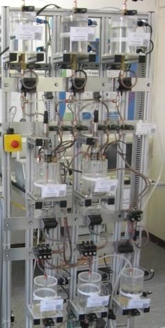
Learn-/Training Document | PA Module P01-01, Edition 02/2020 | Digital Industries, FA Matching SCE Trainer Packages for this Learn-/Training Document • SIMATIC PCS 7 Software Package V9.0 (set of 3) Order No.: 6ES7650-0XX58-0YS5 • SIMATIC PCS 7 Software Package V9.0 (set of 6) Order No.: 6ES7650-0XX58-2YS5 • SIMATIC PCS 7 Software Upgrade Packages (set of 3) Order No.: 6ES7650-0XX58-0YE5 (V8.x V9.0) • SIMIT Simulation Platform with Dongle V10 (contains SIMIT S & CTE, FLOWNET, CONTEC libraries) – 2500 simulation tags Order No.: 6DL8913-0AK00-0AS5 • Upgrade SIMIT Simulation Platform V10 (contains SIMIT S & CTE, FLOWNET, CONTEC libraries) from V8.x/V9.x Order No.: 6DL8913-0AK00-0AS6 • Demo Version SIMIT Simulation Platform V10 Download • SIMATIC PCS 7 AS RTX Box (PROFIBUS) only in combination with ET 200M for RTX – Order No.: 6ES7654-0UE23-0XS1 • ET 200M for RTX Box (PROFIBUS) only in combination with PCS 7 AS RTX Box – Order No.: 6ES7153-2BA10-4AB1 Note that these trainer packages are replaced with successor packages when necessary. An overview of the currently available SCE packages is available at: siemens.com/sce/tp Continued training For regional Siemens SCE continued training, get in touch with your regional SCE contact siemens.com/sce/contact Additional information regarding SCE siemens.com/sce Information regarding use The SCE Learn-/Training Document for the integrated automation solution Totally Integrated Automation (TIA) was prepared for the program "Siemens Automation Cooperates with Education (SCE)" specifically for training purposes for public educational facilities and R&D institutions. Siemens does not guarantee the contents. This document is to be used only for initial training on Siemens products/systems, which means it can be copied in whole or part and given to those being trained for use within the scope of their training. Circulation or copying this Learn-/Training Document and sharing its content is permitted within public training and advanced training facilities for training purposes. Exceptions require written consent from the Siemens. Send all related requests to scesupportfinder.i-ia@siemens.com. Offenders will be held liable. All rights including translation are reserved, particularly if a patent is granted or a utility model or design is registered. Use for industrial customer courses is explicitly not permitted. We do not consent to commercial use of the Learn-/Training Document. For unrestricted in educational / R&D institutions. © Siemens 2020. All rights reserved. 2 p01-01-process-description-v9-tud-0719-en.docx
Learn-/Training Document | PA Module P01-01, Edition 02/2020 | Digital Industries, FA

We wish to thank the TU Dresden, particularly Prof. Dr.-Ing. Leon Urbas and the Michael Dziallas
Engineering Corporation and all other involved persons for their support during the preparation of this
Learn-/Training Document.

For unrestricted in educational / R&D institutions. © Siemens 2020. All rights reserved.                               3
p01-01-process-description-v9-tud-0719-en.docx
Learn-/Training Document | PA Module P01-01, Edition 02/2020 | Digital Industries, FA

Table of contents
1     Classification of process plants......................................................................................................... 5

2     Plant description............................................................................................................................... 6

3     Piping and instrumentation diagram .................................................................................................. 7

4     Interlock and protection functions ................................................................................................... 10

5     Recipe ........................................................................................................................................... 11

6     References .................................................................................................................................... 11

7     Additional information ..................................................................................................................... 12

For unrestricted use in educational / R&D institutions. © Siemens 2020. All rights reserved.                                                                  4
p01-01-process-description-v9-tud-0719-en.docx
Learn-/Training Document | PA Module P01-01, Edition 02/2020 | Digital Industries, FA

Process description
1          Classification of process plants
           To effectively automate process plants, structuring the plant as well as describing its intended
           use is necessary. It is helpful in this case to subdivide process plants into classes that are similar
           with respect to basic requirements for automation engineering. According to [1], the number of
           fundamentally different products and the physical structure of the plant can be used for the
           classification.

           If basically the same product is always produced in a plant, it is called a single product plant.
           When environmental conditions change or compositions of the educts vary, only process
           parameters or settings are expected to be varied in these plants in order to obtain the same
           product. A multi-product plant, on the other hand, produces a variety of products according to
           different processes or according to the same process but with distinctly different parameters.

           From the perspective of automation, the single train plant represents the simplest physical
           structure of a plant. The intermediate stages of the product flow through the units in a fixed
           sequence. A multi-train plant consists of several parallel single trains; however, no product
           transfer is intended between them. The only parts of the process that the single trains share are
           the input material sources and the finished product storage facilities. A multi-train & multi-
           path plant also consists of single trains, but in contrast to the simple multi-train plant, product
           exchange between the trains is possible. Here, the paths can be fixed, dynamic with a fixed
           connection or dynamic with a flexible connection.

For unrestricted in educational / R&D institutions. © Siemens 2020. All rights reserved.                               5
p01-01-process-description-v9-tud-0719-en.docx
Learn-/Training Document | PA Module P01-01, Edition 02/2020 | Digital Industries, FA
2 Plant description
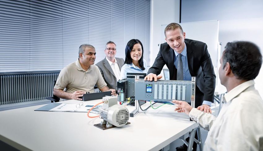
In this instruction module, the laboratory
plant shown in Figure 1 will be automated.
Two reactors that are supplied with different
educts are the centerpiece of the plant. The
reactors can produce various products at
the same time. For this reason, the plant
can be classified as a multi-product
plant and a multi-train & multi-path
plant. It consists of several units that are
connected to each other with a fixed
connection. Depending on the production
process, the paths between the units can
be dynamically interconnected. This
requires complex automation. In the
following chapters of this module, however,
it will be apparent that by taking into
account a few simple principles and rules,
the complex automation system can be
Figure 1: Multi-product and multi-train & multi-path
assembled quite effectively and efficiently laboratory plant of TU Dresden as a training environment
by combining existing blocks of the PCS 7 for modern process control engineering
process control system.
The first unit provides the educts for the reactors. It consists of three educt tanks. Their
instrumentation is identical. To detect whether the tank is empty or full, the level is monitored with
two sensors. With a valve at the outlet and a pump, the educt can be dosed into the second unit.
In addition, the educt is replenished via a valve at the inlet.
The second unit consists of two reactors that have the same dimensions as the educt tanks but
are equipped with other automation instruments. Each reactor is equipped with an agitator and a
heater. The level is continuously measured with an ultrasound sensor, and the temperature with
a PT100 element. The educts can be filled into the reactor via the three valves at the inlet. A
pump at the outlet can be used to fill the reaction product into the other reactor in each case or
into the product tank of the third unit, or to return the rinse water to the rinse tank. An additional
valve at the inlet allows rinse water from the fourth unit to be fed for cleaning the reactor.
For unrestricted in educational / R&D institutions. © Siemens 2020. All rights reserved. 6
p01-01-process-description-v9-tud-0719-en.docxLearn-/Training Document | PA Module P01-01, Edition 02/2020 | Digital Industries, FA
The third unit contains the finished products and consists of two tanks with two sensors that
display the minimum and maximum level. While the reactors can be supplied from all educt
tanks, the product containers are assigned to exactly one reactor. A valve at the inlet of the
product tank opens the path from the reactor to the product tank. One valve each at the outlet of
the product tanks serves the removal of the finished product from the plant.
The fourth unit consists of the rinse water tank. It also is equipped with two sensors to indicate
the minimum and maximum level. A valve and a pump at the outlet allow the rinse water to be
transported to the reactors of the second unit, and the valves at the inlet allow the rinse water to
be transported back from the reactors to the rinse water tank.
3 Piping and instrumentation diagram
Although a textual description of a plant can explain basic relationships, because of its
susceptibility to misinterpretation even in small plants, it is not very suitable for communicating
the joint tasks of process engineering, electro-technical engineering and automation engineering.
This is especially true in the case of large plants with hundreds of devices and several tens of
thousands of measuring points.
For this reason, the piping & instrumentation diagram (P&ID) has therefore developed into
a central engineering document over time. The P&ID documents the structure and function of the
process plant equally for both the process engineering and automation engineering. Figure 2
shows the P&ID of the laboratory plant that is to be automated in this instruction module.
Tanks, valves and pumps as well as functional requirements of the process control are
represented by standardized symbols in the P&ID. The piping between the elements is indicated
as solid lines, the flow of information as dashed lines. For the sake of clarity, Figure 2 presents all
the units in one P&ID.
The unit to which a tank or a process control function belongs can be read from the identification
system. This identification system ensures unambiguous identification for both humans and
computers. As long as people are closely collaborating, they can easily distinguish between
educt tank B001 and product tank B001 based on the context. It becomes more difficult when
communication takes place across several departments, employees are working on many
projects simultaneously and computers are involved. The complete designation for the first educt
tank B001 is therefore =SCE.A1.T1-B001. This allows a clear distinction to be made between
tank B001 in factory SCE, plant A1, unit T1 from similar plants or another unit.
For unrestricted in educational / R&D institutions. © Siemens 2020. All rights reserved. 7
p01-01-process-description-v9-tud-0719-en.docxLearn-/Training Document | PA Module P01-01, Edition 02/2020 | Digital Industries, FA
Figure 2: Configured plant (Part 1)
For unrestricted in educational / R&D institutions. © Siemens 2020. All rights reserved. 8
p01-01-process-description-v9-tud-0719-en.docxLearn-/Training Document | PA Module P01-01, Edition 02/2020 | Digital Industries, FA
Figure 2: Configured plant (Part 2)
For unrestricted in educational / R&D institutions. © Siemens 2020. All rights reserved. 9
p01-01-process-description-v9-tud-0719-en.docxLearn-/Training Document | PA Module P01-01, Edition 02/2020 | Digital Industries, FA
4 Interlock and protection functions
The P&ID is not sufficient to specify all requirements for process control engineering. To ensure
safe plant operation, the controller must monitor process interventions and, if needed, suppress
user input, switch actuators on or off, mutually interlock functions and/or bring the plant to a safe
state. For the plant described above, which is equipped with measuring instruments according to
Figure 2, the following monitoring and interlock functions are required and will be implemented
step-by-step with PCS 7 within the instruction modules:
– An actuator may only be operated when the main switch of the plant is switched on and the
emergency stop switch is unlocked.
– No tank may overflow. That is, there is either a sensor that signals the maximum level, or the
maximum level (here: 1000 ml) is numerically known and is evaluated using the measured
level.
– No pump may draw in air. That is, there is either a sensor that signals the minimum level, or
the minimum level (here: 50 ml) is numerically known and is evaluated using the measured
level.
– A pump must not attempt to take in liquid from a closed valve or pump liquid against a closed
valve.
– The temperatures in the two reactors must not exceed 60 °C.
– The user may only start up the heaters of the two reactors when they are covered with liquid
(here: a minimum of 200 ml in the reactor).
The agitators of the two reactors should only be started up when they come into contact with
liquid (here: a minimum of 300 ml in the reactor).
For unrestricted in educational / R&D institutions. © Siemens 2020. All rights reserved. 10
p01-01-process-description-v9-tud-0719-en.docxLearn-/Training Document | PA Module P01-01, Edition 02/2020 | Digital Industries, FA
5 Recipe
According to [1], a recipe is a specification for how to produce a product according to a
procedure. It describes what is needed to carry out a procedure and what must be done. For the
plant described above, there is the following recipe, which will be implemented with PCS 7 within
this instruction module:
1. First, 350 ml is to be drained from educt tank =SCE.A1.T1-B003 to reactor =SCE.A1.T2-
R001, and at the same time 200 ml is to be drained from educt tank =SCE.A1.T1-B002 to
reactor =SCE.A1.T2-R002.
2. When the filling of reactor =SCE.A1.T2-R001 is finished, the filled liquid is to be heated to
25 °C with the agitator switched on.
3. When the filling of reactor =SCE.A1.T2-R002 is finished, 150 ml of educt A from educt tank
=SCE.A1.T1-B001 is added to reactor =SCE.A1.T2-R002. When this is complete, the
agitator of reactor =SCE.A1.T2-R002 is switched on 10 s later.
4. When the temperature of the liquid in reactor =SCE.A1.T2-R001 has reached 25 °C, the
mixture from reactor =SCE.A1.T2-R002 is pumped to reactor =SCE.A1.T2-R001.
5. The mixture in reactor =SCE.A1.T2-R001 is now to be heated to 28 °C and then drained to
product tank =SCE.A1.T3-B001.
6 References
[1] DIN EN 61512-1 (Edition 2000-01): Batch Control.
For unrestricted in educational / R&D institutions. © Siemens 2020. All rights reserved. 11
p01-01-process-description-v9-tud-0719-en.docxLearn-/Training Document | PA Module P01-01, Edition 02/2020 | Digital Industries, FA
7 Additional information
More information for further practice and consolidation is available as orientation, for example:
Getting Started, videos, tutorials, apps, manuals, programming guidelines and trial software/
firmware, under the following link:
siemens.com/sce/pcs7
Preview "Additional information"
For unrestricted in educational / R&D institutions. © Siemens 2020. All rights reserved. 12
p01-01-process-description-v9-tud-0719-en.docxLearn-/Training Document | PA Module P01-01, Edition 02/2020 | Digital Industries, FA Further Information Siemens Automation Cooperates with Education siemens.com/sce Siemens SIMATIC PCS 7 siemens.com/pcs7 SCE Learn-/Training Documents siemens.com/sce/documents SCE Trainer Packages siemens.com/sce/tp SCE Contact Partners siemens.com/sce/contact Digital Enterprise siemens.com/digital-enterprise Industrie 4.0 siemens.com/future-of-manufacturing Totally Integrated Automation (TIA) siemens.com/tia TIA Portal siemens.com/tia-portal SIMATIC Controller siemens.com/controller SIMATIC Technical Documentation siemens.com/simatic-docu Industry Online Support support.industry.siemens.com Product catalogue and online ordering system Industry Mall mall.industry.siemens.com Siemens Digital Industries, FA P.O. Box 4848 90026 Nuremberg Germany Subject to change and errors © Siemens 2020 siemens.com/sce For unrestricted in educational / R&D institutions. © Siemens 2020. All rights reserved. 13 p01-01-process-description-v9-tud-0719-en.docx
You can also read