DEKKER Controller Operation Manual Programmable Logic Controller (PLC)
←
→
Page content transcription
If your browser does not render page correctly, please read the page content below
Operation
             Manual

DEKKER Controller

 Programmable Logic Controller (PLC)

                          Part No. 9983-0000-E02 Rev A / March 2021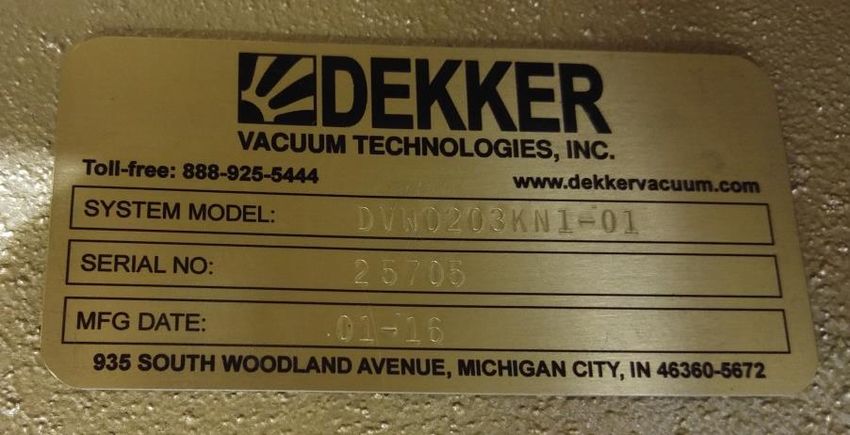
DEKKER CONTROLLER
                                                      OPERATION MANUAL
                                                 TABLE OF CONTENTS

CUSTOMER SERVICE                                                               4

CONTACT INFORMATION                                                             4
ORDER INFORMATION                                                               4

INTRODUCTION                                                                   5

DEKKER CONTROLLER KEYPAD                                                       5

BATTERY                                                                        6

CONTROLER INPUT/OUTPUT LAYOUT                                                  7

CURRENT INPUT/OUTPUT ASSIGNMENTS                                               8

INPUTS                                                                          8
OUTPUTS                                                                         8

ENTERING PASSWORD                                                              9

CHANGING VACUUM UNITS                                                          10

CHANGING VACUUM CUTIN AND CUTOUT                                               12

MULTIMACHINE SETUP                                                             13

TEMPERATURE WARNINGS AND FAULTS                                                13

SETTING DATE AND TIME                                                          14

ENTERING KEYCODES                                                              15

COOLING FAN                                                                    16

ROTATION                                                                       17

MANUAL ROTATION                                                                17

SCAVENGER OUTPUT                                                               18

FAULTS AND FAULT LOG                                                           19

AUTOSTART                                                                      20

MAINTENANCE SCHEDULES                                                          21

DEKKER Vacuum Technologies, Inc. / Part No. 9983-0000-E02 Rev A / March 2021    2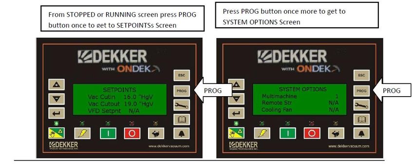
RESETTING MAINTENANCE SCHEDULE HOURS                                           24

DP INLET                                                                       25

REMOTE START STOP                                                              25

NETWORK OPTIONS                                                                26

DEKKER Vacuum Technologies, Inc. / Part No. 9983-0000-E02 Rev A / March 2021    3
CUSTOMER SERVICE
Contact information

    935 SOUTH WOODLAND AVENUE, MICHIGAN CITY, IN 46360-5672
    TEL.: 219-861-0661 – FAX: 219-861-0662 – TOLL-FREE: 888-925-5444
    Bus. Hours: 7:30 a.m. – 4:30 p.m. CST
    Website:    www.DEKKERvacuum.com

Order Information
    When calling for service, parts or system information always have the pump or system model number and
    serial number(s) ready. Refer to the bill of lading, the gold-colored system information plate attached to the
    system (see image below), or the white label on the inner door of the control panel (see image below).

                                                   Control panel nameplate label
    Parts should be purchased from the nearest authorized DEKKER Vacuum Technologies, Inc. (hereafter
    referred to as DEKKER) representative (visit www.dekkervacuum.com to find a distributor near you via the
    Distributor Locator) or from the vacuum pump system supplier. If, for any reason parts, cannot be obtained in
    this manner, contact the factory directly.

DEKKER Vacuum Technologies, Inc. / Part No. 9983-0000-E02 Rev A / March 2021                                         4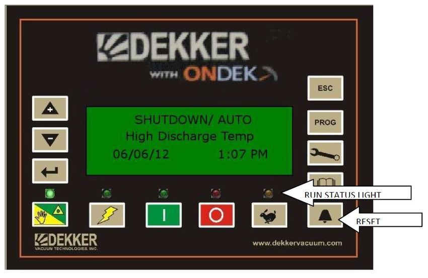
INTRODUCTION
   The Dekker Controller provides for system control as well as monitoring of system status. Service functions
   include display of spare parts list, maintenance schedules, service history, and logging of fault conditions.
    The Dekker Controller includes a 4-line large-font LCD (Liquid Crystal Display), a durable Lexan membrane
    keypad, and multiple status LEDs. Communication between controllers is via RS-485 for multimachine systems.
    Input/Output (I/O) includes 9 digital (24VDC) inputs and 7 dry relay contact outputs. Analog I/O includes 2
    RTD (Resistance Temperature Detectors) inputs, four 0-10VDC/4-20mA inputs, one 0-10VDC output, and
    one 4-20mA output. Power input to the controller is 24VDC.

DEKKER CONTROLLER KEYPAD
    The Dekker Controller text display, buttons, and LEDs are described below.

          4 line LCD Display
          UP/DOWN arrow button is used to navigate menus and change values for setpoints, real-time clock,
          vacuum units, and temperature units.
          ENTER button is used to select menu items, menus and values.
          HAND/AUTO LED is used to identify the run status of the system. Orange = Hand (manual
          operation). Green = Auto.
          HAND/AUTO button is used to alternate between Hand (manual operation) and Auto mode.
          POWER ON LED is used to indicate if the controller power is on. Red = Controller power is
          on.
          POWER button is used to turn the controller on and off.
          ON LED is used to display if the system is running or in standby mode. Green =
          System is either running or in Standby mode.

DEKKER Vacuum Technologies, Inc. / Part No. 9983-0000-E02 Rev A / March 2021                                       5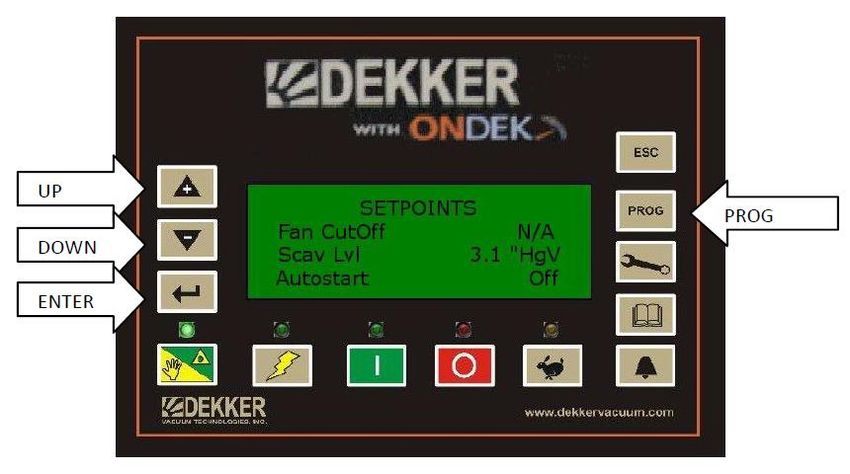
ON button is used to start the system.
OFF button is used to stop the system.
OFF LED is used to display if the system is stopped. Red = System is stopped.
RUN STATUS LED is used to display the current run status. Green = System is
running. Orange = System is in Standby or Auto mode. Red = System is stopped.
RESET button is used to reset faults. Note: Fault condition must be cleared before the Reset
button will reset the fault.
LOG button is used to access the Fault History Log menu.
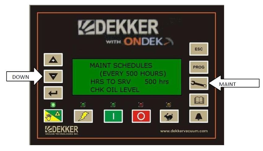
MAINTENANCE button (MAIN) is used to access menu for the Spare Parts List, Maintenance
Schedule and Service History.
PROGRAM button (PROG) is used to access the Programming menu for Setpoints,
Clock, Vacuum Units, Temperature Units and other keycode options that are
purchased after the original sale (such as hi or low-level switches, backpressure, etc).
ESCAPE button (ESC) is used to return to the Run/Standby/Stopped screen.
BATTERY
The Dekker Controller may be shipped with a battery protector placed between the battery clip and the
surface of the battery, it may be a rubber sleeve around the clip or a small plastic insulator between the
clip and battery. This must be removed before applying power to the controller. If not removed the
controller will not retain Date, Time and other values that are written to the controller for setup. The
controller cannot be flashed with new firmware until this is removed. To remove, use a pair of needle
nose pliers and pull from clip.
DEKKER Vacuum Technologies, Inc. / Part No. 9983-0000-E02 Rev A / March 2021 6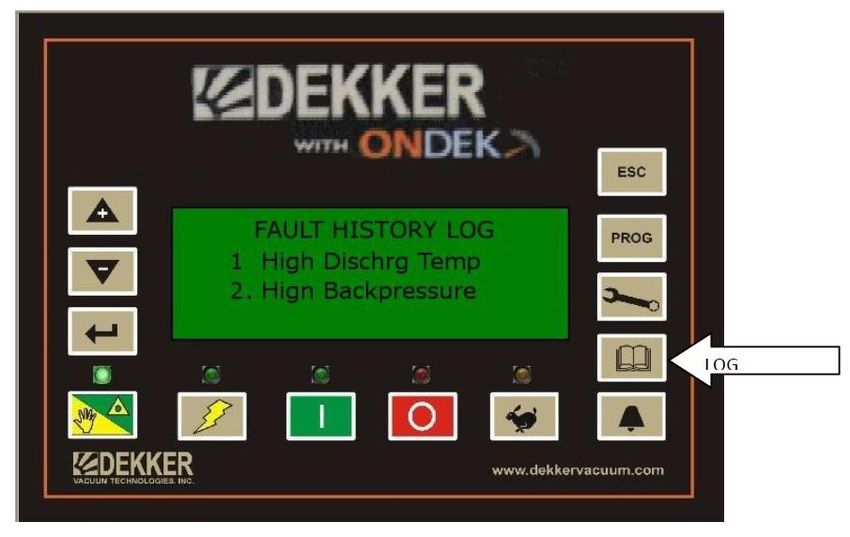
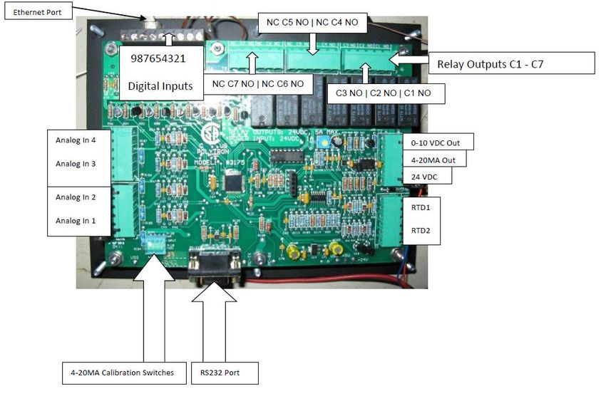
CONTROLER INPUT/OUTPUT LAYOUT

DEKKER Vacuum Technologies, Inc. / Part No. 9983-0000-E02 Rev A / March 2021   7
CURRENT INPUT/OUTPUT ASSIGNMENTS
Inputs
                     Digital Inputs                   Analog Inputs                 RTD Inputs
                E-Stop                           Vacuum                        RTD1 – Aux Temp
                Overloads                        Backpressure                  RTD2 – Discharge Temp
                Aux Contact Vac Pump             Circ Pump Pressure
                Low Fluid Level                  Diff Pressure
                High Fluid Level
                Remote Start
                Remote Stop
                Circ Pump Overload
                External Warning

    Note: Analog input 4 is a 0-15 psia transducer used in conjunction with Analog input 1 transducer to measure
    the difference in vacuum across an inlet filter.

Outputs
                                                       Relay Outputs
                                        C1/NO = Vac Pump Motor Starter
                                        C2/NO = Local Lag Light
                                        C3/NO = Horn Output
                                        C4/NO = Remote Lag Light
                                        C5/NO = All Fault Out
                                        C6/NO = Scavenger Valve Out
                                        C7/NO = Cooling Fan

DEKKER Vacuum Technologies, Inc. / Part No. 9983-0000-E02 Rev A / March 2021                                   8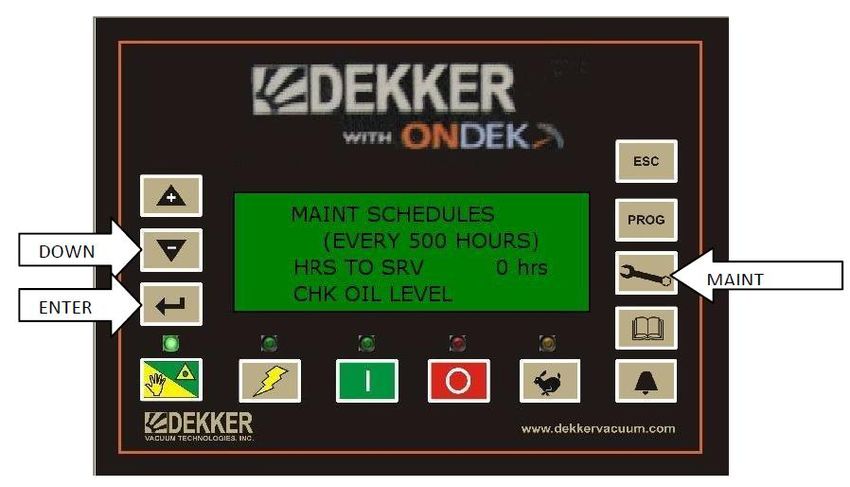
ENTERING PASSWORD
The Dekker Controller provides password protected settings and variables. To access these protected areas, a
password needs to be entered.

Press and hold the ESC button until Password 0 appears at the bottom of the screen.

Press the MAINT button twice, which enters the password 33, and then press ENTER. You now have access to
change the Controller settings.

To restore Basic Access, press and hold the ESCAPE (ESC) button for two seconds. The screen will display the
words Access Locked. Basic Access is also restored upon powering the controller off and on. If the DEKKER
Controller has no activity (no buttons pushed) for 5 minutes, it will default back to Basic Access.

DEKKER Vacuum Technologies, Inc. / Part No. 9983-0000-E02 Rev A / March 2021                                   9
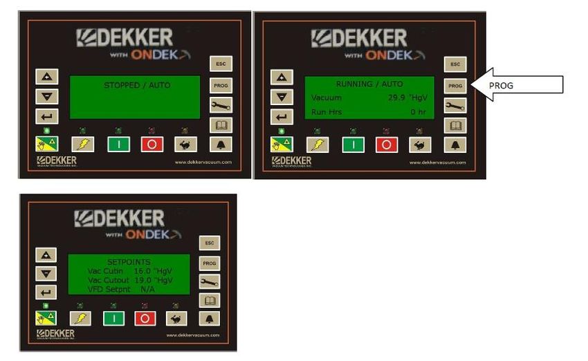
CHANGING VACUUM UNITS
Enter Password

If the system is STOPPED or RUNNING press the PROG button once to view the Setpoints screen. If HgV is
already set for vacuum units, you will see VAC CUTIN and VAC CUTOUTt in HgV units.

DEKKER Vacuum Technologies, Inc. / Part No. 9983-0000-E02 Rev A / March 2021                             10
To change to another type of unit, use the DOWN arrow to scroll to Vacuum Unit then press ENTER.

Using the UP arrow to change unit, you will have a choice of TORR, HgV or Millibars. Once selection is made,
press ENTER to save.

DEKKER Vacuum Technologies, Inc. / Part No. 9983-0000-E02 Rev A / March 2021                                   11
CHANGING VACUUM CUTIN AND CUTOUT
Enter Password

If the system is STOPPED or RUNNING press the PROG button once to view the Setpoints screen.

Press the UP or DOWN button if necessary to select VAC CUTIN then press ENTER. Once ENTER is pressed,
use UP or DOWN arrows to change the value and then press ENTER to save. Repeat for VAC CUTOUT.

DEKKER Vacuum Technologies, Inc. / Part No. 9983-0000-E02 Rev A / March 2021                            12
MULTIMACHINE SETUP
Multimachine allows two or more Controllers to communicate and rotate Lead and Lag pumps based on hours
Run. When rotation occurs the pump with the least hours will rotate to Lead. This helps to keep the run hours
balanced amongst the networked pumps. To set up for multimachine CAT5 Ethernet cables are run from panel to
panel. Cables must be run before setting the Controller for multimachine operation. Once cables are run go to first
Controller and Enter Password.
Enter the password on the first controller
Press PROG button twice to view System Options Screen
Press DOWN arrow until Multimachine is selected
Press ENTER
Even though multimachine may already be set for 1 use UP button to move to 2 then back to 1
Press ENTER and the controller will reboot
Enter the password on the second controller
Follow the same steps as for the first controller but set the multimachine to 2
Continue this process for all networked systems
After the controllers reboot they should show Units Found. The number of units found should match the number
of systems networked.
TEMPERATURE WARNINGS AND FAULTS
Temperature warnings and faults are factory set, It is not recommended to change these settings without
consulting with a Dekker Service Technician.
DEKKER Vacuum Technologies, Inc. / Part No. 9983-0000-E02 Rev A / March 2021 13SETTING DATE AND TIME Enter Password Press PROG once to view Setpoints screen Using the DOWN arrow to scroll to the Date and press ENTER Use UP and DOWN arrows to change Date, press ENTER to save. Use UP and DOWN arrows to scroll to the Time and press ENTER Use UP and DOWN arrows to change Date, press ENTER to save. DEKKER Vacuum Technologies, Inc. / Part No. 9983-0000-E02 Rev A / March 2021 14
ENTERING KEYCODES
Keycodes are used to enable available options. Keycodes are 7 digits. All keycodes are entered with 2 leading 0s.

Enter Password

Using the DOWN key, find the option needed and press ENTER. Keycode will appear with one 0. To
enter the keycode for this option use the UP/DOWN keys to scroll to the required value for the digit
and press ENTER. Continue this process until the entire keycode is entered. Upon pressing ENTER for
the last digit, the option previously displaying N/A will change to YES.

                             Option Description                                Keycode
                      Hi Level Switch                              001159823
                      Low Level Switch                             001146833
                      Temperature Switch                           001117934
                      Vacuum Switch                                001134668
                      Auxiliary RTD Temperature                    001182214
                      Differential Pressure Inlet Filter           001114236
                      Back Pressure Transducer                     001196511
                      Multimachine                                 001127744
                      Remote Start/Stop                            001169856
                      Cooling Fan                                  001149877

DEKKER Vacuum Technologies, Inc. / Part No. 9983-0000-E02 Rev A / March 2021                                        15
COOLING FAN The Dekker Controller is equipped with a temperature control to operate a cooling fan when applicable. This feature requires a cooling fan keycode to be entered (see entering keycodes above). Once the cooling fan keycode is entered press the PROG button until you see the SETPOINT screen. Use DOWN arrow to scroll to FAN CUTON and FAN CUTOFF. These are the setpoints to turn the fan on and off. They can be changed by entering password, scroll back to the settings. Press ENTER then use UP/DOWN arrows to change values. You must press ENTER again to save. Normally Open Output C7 is used for this purpose. DEKKER Vacuum Technologies, Inc. / Part No. 9983-0000-E02 Rev A / March 2021 16
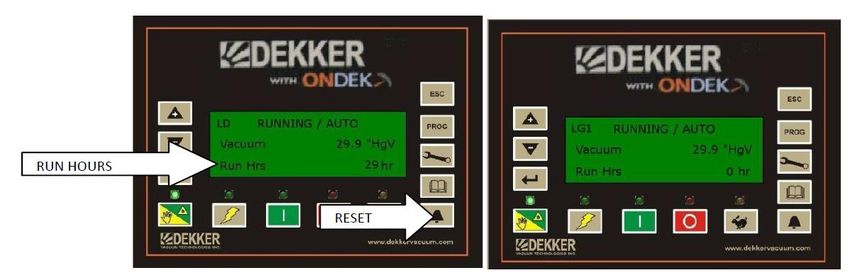
ROTATION
When set up for multimachine the system will rotate pumps every 24 hours if needed. For rotation to occur, the
Lead pump must have the most run hours. When this condition is met and the time for rotation occurs, the Lag
pump will become the lead pump. If this condition is not met rotation will not occur. If a triplex or higher system
rotation for each pump will occur in order based on run hours of each pump.

MANUAL ROTATION
The pumps can be rotated manually, but the same condition above applies, the Lead must have the most hours.

To rotate pumps manually, on the Lead pump, press and hold RESET button until you see the text
“Manual Transfer” appear on the screen, then release the button. Wait a few seconds and you will see
the upper text “LD” move to the opposite controller, the text “LG1” will move to where the “LD” was
previously.

DEKKER Vacuum Technologies, Inc. / Part No. 9983-0000-E02 Rev A / March 2021                                      17
SCAVENGER OUTPUT
Output 6 on the controller is used for a bleed valve. This output cycles on for 30 Secs and off for 9 minutes based
on vacuum level. The vacuum level for cycling to occur is adjustable via the Setpoint menu on the Dekker
Controller.
Enter password
Press PROG until Setpoints screen is shown.
Using DOWN arrow scroll to SCAV LVL
Press ENTER
Use UP/DOWN arrows to change value
Press ENTER to save.
DEKKER Vacuum Technologies, Inc. / Part No. 9983-0000-E02 Rev A / March 2021 18FAULTS AND FAULT LOG If a fault occurs the fault will be displayed on the screen and recorded in the fault log. Faults include Overload, Temperature and in some versions of firmware Back Pressure. The Temperature and Back Pressure faults are adjustable from the setpoint screen, but it is not recommended to change these without consulting with a Dekker Technician. Changing these values could result in pump damage. Below is what is shown on the screen when a temperature fault occurs. The Run Status light will also turn red and flash so you can see a fault has occurred from a distance. Faults are cleared using the Reset button, but will not clear until the condition that caused the fault is cleared. When the fault occurs, it is recorded in the fault log. The fault log will record up to 10 faults. When this is reached the most recent fault is recorded at the top of the list and fault at the bottom of the list is removed. To view the fault log press the Log button. Each fault can be selected to view what values such as Vacuum, Back Pressure etc… were at the time of the fault and up to 10 minutes prior to the fault. To view this detail use UP or DOWN key to select the fault. Then press ENTER. The first screen shows what was occurring at the time of the fault, use DOWN arrow to view more information. Press ENTER again to view what was occurring 1 minute prior to fault. Press again for 2 minutes prior. You can continue pressing ENTER to view up to 10 minutes prior to fault. DEKKER Vacuum Technologies, Inc. / Part No. 9983-0000-E02 Rev A / March 2021 19
AUTOSTART
The Dekker controller is equipped with Autostart. This feature allows automatic restart of system when power
returns from a power loss. To enable this feature press PROG button to show SETPOINTS screen. Use DOWN
arrow to select Autostart. Press ENTER. Use UP arrow to change to ON. Press ENTER to save. If system is
multimachine, this must be set on all controllers.

DEKKER Vacuum Technologies, Inc. / Part No. 9983-0000-E02 Rev A / March 2021                               20
MAINTENANCE SCHEDULES
Pressing the MAINT button once will display the screen below:
This screen shows the support phone number for Dekker Vacuum along with the Serial number and model
number of the system.

Pressing the MAINT button twice will display the spare parts list for the system. This list can be used for ordering
parts if needed. Part numbers will appear in place of the XXXX-XXXX-XXX. These numbers are entered at the
factory. Use DOWN arrow to navigate through the list.

Pressing MAINT a third time will show the maintenance schedule intro screen. This screen also displays the
current Run Hours.

DEKKER Vacuum Technologies, Inc. / Part No. 9983-0000-E02 Rev A / March 2021                                       21
Press MAINT a fourth time to view the maintenance schedule. This list provides a recommended maintenance
schedule along with intervals. The time in hours until the maintenance is due counts down and can be seen on the
Dekker Controller LCD in this area. Proper maintenance is necessary to provide proper performance and can
prolong the life of your system. The UP and DOWN ARROW buttons can be used to navigate through the list.
Proper response and service of service due message is highly recommended.

Press MAINT a fifth time to view the Service History. Service history is recorded with date and time of service;
each time the recommended service is completed and the maintenance schedule is reset.

DEKKER Vacuum Technologies, Inc. / Part No. 9983-0000-E02 Rev A / March 2021                                       22
Pressing MAIN again will return you to the Dekker support screen. Pressing ESC at anytime will return to the
main screen.

DEKKER Vacuum Technologies, Inc. / Part No. 9983-0000-E02 Rev A / March 2021                                   23
RESETTING MAINTENANCE SCHEDULE HOURS
Enter Password
When maintenance is due you will see a warning on the screen letting you know that maintenance is due on the
system. To remove this warning you must reset the maintenance interval. Press the MAINT button until you see
the maintenance interval screen. The 0 shows the period has expired and generates the warning on the screen.
You must reset the HRS To Srv to 500 or the schedule selected. Use DOWN key to select HRS TO SRV and
press ENTER. Use UP key to reset to the correct interval (500 in this case). Press ENTER again to save, this last
press of ENTER also records the date and time this service was completed in the Service History log.. Pressing
ESC will take you back to the main screen and the warning will be gone. Note: warnings and faults only show in
run mode.

DEKKER Vacuum Technologies, Inc. / Part No. 9983-0000-E02 Rev A / March 2021                                        24
DP INLET
DP Inlet is a differential pressure across the inlet filter to monitor the filter. When the differential reaches the
preset point a warning will show on the screen, once the filter is cleaned and the differential is reduced the
warning will go away. A keycode (See Entering Keycodes) is required to enable this feature also an extra
transducer is required.

REMOTE START STOP
To enable remote Start/Stop first the inputs must be wired. A NO momentary button is wired from the +24VDC
on one side and to Digital input 6 on the other side. A NC momentary button is wired to +24VDC on one side
and to Digital input 7 on the other. Both buttons must be momentary. Then to enable Remote Start/Stop you
must enter the keycode. (See Entering Keycodes)

DEKKER Vacuum Technologies, Inc. / Part No. 9983-0000-E02 Rev A / March 2021                                           25
NETWORK OPTIONS
Press PROG
Continue to press PROG until Network screen appears. This screen allows for changing Static IP address, Subnet
mask and Gateway for network use. You can also turn DHCP on if a DHCP server is available to assign the
controller an IP address. This screen should only be changed by qualified personnel.

DEKKER Vacuum Technologies, Inc. / Part No. 9983-0000-E02 Rev A / March 2021                                 26
You can also read