IOM_Signals_Comparison_1 - Comparison of signals via IOM AURIX TC2xx Microcontroller Training - Infineon Technologies
←
→
Page content transcription
If your browser does not render page correctly, please read the page content below
IOM_Signals_Comparison_1
Comparison of signals via IOM

AURIX™ TC2xx Microcontroller Training
V1.0.0
               Please read the Important Notice and Warnings at the end of this document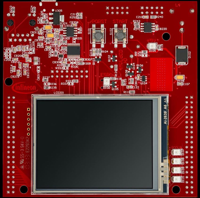
Scope of work

Two PWM signals are compared by the IOM module.

Two PWM signals are routed through the port pins to the Input Output
Module (IOM) as monitor and reference respectively. The signals are
continuously compared using exclusive OR. If the newly formed signal
(XOR) is in high state outside the acceptable propagation window, an LED is
switched on.

2020-01-17               Copyright © Infineon Technologies AG 2020. All rights reserved.   2
Introduction

› In this example, the following modules are used:
  – IOM (Input Output Monitor)
  – SMU (Safety Management Unit)
  – IR (Interrupt Router)
  – GTM (Generic Timer Module)

› All the modules above are presented in this tutorial, although a specific
  focus is given to the IOM and the SMU modules.

2020-01-17                Copyright © Infineon Technologies AG 2020. All rights reserved.   3
Introduction

             IOM                      SMU                                              IR            GTM

›    The Input Output Monitor (IOM) serves as a smart I/O comparison unit:
     – Checks for the correct operation of system peripheral outputs that might serve and/or control
        externally-attached hardware
     – Monitors the correct operation of the hardware itself, including any sensors whose signals
        might serve as an input to the monitoring function
›    The IOM can be used to either monitor a signal for a desired behaviour or compare a monitor
     signal with a reference signal for safety requirements.
›    Up to 16 monitoring points can be configured, with the capability to generate a system event that
     can be driven from:
     – one individual configuration
     – several individual configurations
     – multiple occurrences of a monitored condition
     – combination of several conditions depending upon configuration
›    Features of IOM:
     – 16 Filter & Prescaler Channels
     – 16 Logic Analyzer Modules (LAMs)
     – 1 EXOR combiner, configurable, to select a range up to 8 GTM inputs
     – 1 Event Combiner Module (ECM), taking the 16 local event signals and generating a system
        event signal from a single, combination or multiple local event(s)
     – System Peripheral Bus (SPB) interface for configuration and status register interaction

2020-01-17                         Copyright © Infineon Technologies AG 2020. All rights reserved.         4
Introduction
IOM SMU IR GTM
› The Safety Management Unit (SMU) provides a generic interface to manage the
behaviour of the microcontroller under the presence of faults.
› It centralizes all the alarm signals related to the different hardware and software-based
safety mechanisms.
› The alarms are classified into alarm groups. This does not define any hierarchy but
only a logical mapping to internal configuration registers. The configuration options
therefore specify the behaviour of the SMU when an alarm event is detected:
– The alarm event can trigger an internal action
– The alarm event can indicate a fault to the external environment via the Error Pin
› Internal action resulting from an alarm event can be interfaced to the Interrupt Router
via the following signals:
– SMU Interrupt Request 0
– SMU Interrupt Request 1
– SMU Interrupt Request 2
› The SMU in combination with the embedded safety mechanisms enables the detection
of more than 99% of the critical failure modes of the microcontroller.
2020-01-17 Copyright © Infineon Technologies AG 2020. All rights reserved. 5Introduction
IOM SMU IR GTM
› The interrupt system in the AURIX™ TC2xx devices is implemented in the
Interrupt Router (IR).
› Interrupt Requests (or Service Requests) can be serviced either by the
CPUs or by the DMA module (both called Service Providers).
› An interrupt can be triggered by:
– Each module connected to the IR
– External peripherals
– Software via General Purpose Service Requests (GPSR)
› Each Service Provider supports up to 255 service priority levels:
– 0 to disable the interrupt
– 255 for highest priority
2020-01-17 Copyright © Infineon Technologies AG 2020. All rights reserved. 6Introduction
IOM SMU IR GTM
› The Generic Timer Module (GTM) is a modular timer unit designed to
accommodate many timer applications.
› It has an in-built Timer Output Module (TOM) that can offers 16 independent
channels to generate output signals.
› The Clock Management Unit (CMU) is responsible for clock generation of the
GTM. The Fixed Clock Generation (FXU) is one of its subunits and it provides five
predefined non-configurable clocks for GTM modules, including the TOM.
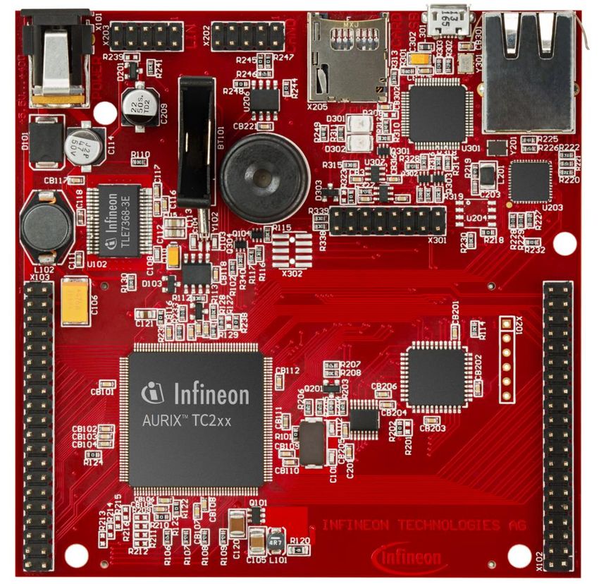
2020-01-17 Copyright © Infineon Technologies AG 2020. All rights reserved. 7Hardware setup
This code example has been
developed for the board
KIT_AURIX_TC297_TFT_BC-Step.
For the first signal, connect the two port pins
P15.6 PWM signal and P33.1
IOM reference input together. For the second signal,
connect the two port pins P15.5 PWM signal and
P33.2 IOM monitor input to each other.
2020-01-17 Copyright © Infineon Technologies AG 2020. All rights reserved. 8Implementation
•1 The GTM module
generates two PWM IR SMU
signals
4
•2 The IOM monitors the
SPB 3
PWM signal and
compares it with the GTM IOM
reference PWM signal
REF MON
•3 If an event is generated, P33.2
2
an SMU internal alarm is TOM0/TOM1
ATOM0_CH0 P33.1
triggered
P15.5
1
•4 The IR handles the SMU
alarm as Software P15.6
interrupt
2020-01-17 Copyright © Infineon Technologies AG 2020. All rights reserved. 9Implementation
Configuring the TOM 1 GTM
› The IfxGtm_Tom_Pwm_Config structure allows to set the following parameters to initialize
the module:
– tom – Selection of the TOM which is counting (TOM 0 and TOM 1 in this training)
– tomChannel – Selection of the channel which is driving the LED (Channel 0 in this
training)
– period – Setting of the period for the PWM signal to the desired value
– pin.outputPin – Selection of the LED as the output pin
– synchronousUpdateEnable – Enabling of Synchronous Update of the timers
› After configuration, the function IfxGtm_Tom_Pwm_init() initializes and activates the TOM
with the user configuration
› Start the PWM with the function IfxGtm_Tom_Pwm_start()
All the functions used for the configuration of the TOM are provided by the iLLD header
IfxGtm_Tom_Pwm.h.
2020-01-17 Copyright © Infineon Technologies AG 2020. All rights reserved. 10Implementation Configuring the IOM – initIOM() 2 IOM Such as the other modules, the IOM needs at first to be enabled. This is done via the iLLD function IfxIom_enableModule(). Before starting to configure the parameters, the configuration drivers need to be initialized (see code for more detailed information): › IfxIom_Driver – Declare IOM driver › IfxIom_Driver_Config – Used to configure the IOM › IfxIom_Driver_Lam – Declare LAM driver › IfxIom_Driver_LamConfig – Used to configure the LAM 2020-01-17 Copyright © Infineon Technologies AG 2020. All rights reserved. 11
Implementation

Configuring the IOM – initIOM()                                                                   2   IOM

Then, the configuration of the LAM regarding the example continues by setting the key
parameters as following:
› mon.input selecting the monitor input port
› ref.input selecting the reference input port
› eventWindow.controlSource determining the signal generating the events
› eventWindow.clearEvent defining when to start a new event window
› eventWindow.threshold defining the event window size
› eventWindow.inverted defining whether the event should happen before or after the
   threshold
› event.source defining the sourced signal
› event.trigger defining on which condition the event is triggered
› systemEventTriggerThreshold setting the amount of events before generating an alarm

The configuration is thereafter applied to the module through the iLLD function
IfxIom_Driver_initLam() and the LAM module can be enabled with
IfxIom_Driver_enableLamEvent().

2020-01-17                      Copyright © Infineon Technologies AG 2020. All rights reserved.       12
Implementation
Configuring the SMU – initSmu()                                                                                           3 SMU

The SMU is first enabled and started with the iLLD function IfxSmu_start().
To allow the configuration of the SMU, the module must be unlocked. This can be done with the iLLD
function IfxSmu_unlock().

The function IfxSmu_setAlarmConfig() has to be called with the following parameters:
›     IfxSmu_Alarm_IomPinMismatchIndication is used to identify the alarm refering to the IOM.
›     To configure the SMU behavior when an alarm occurs, an Interrupt Generation Configuration Set
      (IGCS) has to be selected. In this example, IGCS0 (IGCS1-2 are also available) identifies with
      IfxSmu_AlarmConfig_interruptSet0.

Since IGCS0 has been selected, it has to be enabled in SMU Alarm Global Configuration (AGC)
setting to 1 the bit 0 of the SMU_AGC register:

MODULE_SMU.AGC.U = 0x1;                                                                                             SMU_AGC
                                                                                                     Alarm Global Configuration

                                                                                                                                    1
    31 30 29   ...                                               ...                                            ...   2    1        0

Lastly, the SMU module has to be relocked with the function IfxSmu_lock().
All the above functions are contained in the header file IfxSmu.h.

2020-01-17                         Copyright © Infineon Technologies AG 2020. All rights reserved.                             13
Implementation Configuring the Interrupt Router – initIR() 4 IR To handle the Software interrupt generated by the SMU module, the Service Request Register (SRC) from the SMU0 (identifying the SMU Interrupt Generation Configuration Set 0) has first to be fetched. Then calling IfxSrc_init() allows: › The selection of the Service Provider (CPU0 in this example) › The setting of the interrupt priority level (10 in this example) The function IfxSrc_init() can be found in the header file IfxSrc.h. 2020-01-17 Copyright © Infineon Technologies AG 2020. All rights reserved. 14
Run and Test

After code compilation and flashing the device, observe the behavior of the
LED:

› Check if the LED D107 (1) is
  switched off when the duty
  cycle of the monitored PWM
  is inside the acceptable
  propagation window and
  switched on when outside.

                                                                                            1

2020-01-17               Copyright © Infineon Technologies AG 2020. All rights reserved.   15
Run and Test
Graphic explanation
When the falling edge of the monitored PWM is out of the acceptable propagation window, an
event is generated, triggering an internal SMU alarm.
Acceptable propagation window (threshold)
Reference PWM
t
Monitor PWM
t
Falling edge out of the acceptable
propagation window
2020-01-17 Copyright © Infineon Technologies AG 2020. All rights reserved. 16References
› AURIX™ Development Studio is available online:
› https://www.infineon.com/aurixdevelopmentstudio
› Use the „Import...“ function to get access to more code examples.
› More code examples can be found on the GIT repository:
› https://github.com/Infineon/AURIX_code_examples
› For additional trainings, visit our webpage:
› https://www.infineon.com/aurix-expert-training
› For questions and support, use the AURIX™ Forum:
› https://www.infineonforums.com/forums/13-Aurix-Forum
2019-10-17 Copyright © Infineon Technologies AG 2019. All rights reserved. 17Trademarks
All referenced product or service names and trademarks are the property of their respective owners.
Edition 2020-01 IMPORTANT NOTICE For further information on the product,
Published by The information given in this document shall in no technology, delivery terms and conditions and
Infineon Technologies AG event be regarded as a guarantee of conditions or prices please contact your nearest Infineon
81726 Munich, Germany characteristics (“Beschaffenheitsgarantie”) . Technologies office (www.infineon.com).
With respect to any examples, hints or any typical
© 2020 Infineon Technologies AG. WARNINGS
values stated herein and/or any information
All Rights Reserved. Due to technical requirements products may
regarding the application of the product, Infineon
contain dangerous substances. For information
Technologies hereby disclaims any and all
Do you have a question about this on the types in question please contact your
warranties and liabilities of any kind, including
document? nearest Infineon Technologies office.
without limitation warranties of non-infringement
Email: erratum@infineon.com
of intellectual property rights of any third party. Except as otherwise explicitly approved by
Infineon Technologies in a written document
Document reference In addition, any information given in this
signed by authorized representatives of Infineon
IOM_Signals_Comparison_1 document is subject to customer’s compliance
Technologies, Infineon Technologies’ products
with its obligations stated in this document and
may not be used in any applications where a
any applicable legal requirements, norms and
failure of the product or any consequences of the
standards concerning customer’s products and
use thereof can reasonably be expected to result
any use of the product of Infineon Technologies in
in personal injury.
customer’s applications.
The data contained in this document is exclusively
intended for technically trained staff. It is the
responsibility of customer’s technical
departments to evaluate the suitability of the
product for the intended application and the
completeness of the product information given in
this document with respect to such application.You can also read